Integration and commissioning of the ATLAS Muon spectrometer
Abstract
The ATLAS experiment at the Large Hadron Collider (LHC) at CERN is currently waiting to record the first collision data in spring 2009. Its muon spectrometer is designed to achieve a momentum resolution of . The spectrometer consists of a system of three superconducting air-core toroid magnets and is instrumented with three layers of Monitored Drift Tube chambers (Cathode Strip Chambers in the extreme forward region) as precision detectors. Resistive Plate Chambers in the barrel and Thin Gap Chambers in the endcap regions provide a fast trigger system.
The spectrometer passed important milestones in the last year. The most notable milestone was the installation of the inner layer of endcap muon chambers, which constituted the last big piece of the ATLAS detector to be lowered in the ATLAS cavern. In addition, during the last two years most of the muon detectors were commissioned with cosmic rays while being assembled in the underground experimental cavern. We will report on our experience with the precision and trigger chambers, the optical spectrometer alignment system, the level-1 trigger, and the ATLAS data acquisition system. Results of the global performance of the muon system from data with magnetic field will also be presented.
I INTRODUCTION
The ATLAS detector is nearing its completion after a 15-years effort, and the Large Hadron Collider is scheduled to start providing collisions in spring 2009. The initial (design) luminosity will be () , with inter-bunch separation of () .
The precision measurement of muon tracks is performed, over most of the spectrometer acceptance, by Monitored Drift Tube (MDT) chambers. Three layers of MDT chambers arranged in concentric cylinders constitute the barrel MDT system. In the forward region, MDT chambers are installed in three wheels, with a coverage up to . The MDT chambers are continuously monitored for misalignments and deformations by a network of optical lines, which allow for the achievement of the design resolution on sagitta measurements. In the most forward part of the inner layer of the muon spectrometer, where the background rate is expected to reach , Cathode Strip Chambers (CSC) are used. Muons are triggered by three double layers of Resistive Plate Chambers (RPC) in the barrel region (), and by three stations of Thin Gap Chambers (TGC) in the endcap region ().
The largest part of the muon spectrometer is embedded in a toroidal magnet field, provided by three magnets: one barrel toroid, and two endcap toroids, one per side. The total bending power is 2-6 Tm in the barrel region, and 1-7 Tm in the endcap regions.
The four technologies of muon spectrometer chambers and the system of toroidal magnets are described in detail in :2008zz .
II HARDWARE STATUS
The MDTs are built from -diameter aluminum tubes equipped with a -diameter gold-plated Tungsten-Rhenium wire, kept at 3080 V with respect to the tube wall. This setup provide a single-hit resolution of in the bending direction of tracks. The most common types of chamber contain 6 to 8 layers of drift tubes, which results in a chamber resolution around .
All MDT chambers have been installed in the ATLAS cavern, and commissioning with cosmic rays is well under way. The latest milestones were the installation of the inner station of the endcap system, the Small Wheels, and of the last seventy-two chambers of the outer station of the endcap system, the Endcap Outer (EO) station. This last step marked the completion of the MDT installation. A set of 62 extra endcap (EE) chambers has been staged for installation in 2009-2010.
The MDT system, excluding the EE chambers, consists of 1088 chambers, for about 339,000 readout channels. The fraction of readout channels which are not included in the ATLAS Trigger and Data Acquisition (TDAQ) chain is in the order of . It will be reduced of one order of magnitude after the interventions planned during the winter 2009 shutdown.
Deformations and alignment of MDT chambers are actively monitored by a set of optical rays. The alignment of chambers with respect to the rest of ATLAS (in particular, the inner detector) is studied utilizing cosmic rays and beam data. The alignment system is fully commissioned, and even if a small fraction of the optical lines is not usable (either for a camera or laser fault, or unexpected obstacles along a line), the redundancy of the system covers for the missing parts. The fraction of working sensors is about ( in the MDT barrel). The largest fraction of interrupted polar lines, which are used to align chambers in different stations (inner, middle, outer), is in one of the Endcap wheels, where of the polar lines are working. The recovery of the missing lines requires an adjustment of the position of that Endcap middle wheel, which is scheduled for the next shutdown. The chamber alignment fit, which is a measure of the internal consistency of the sensor measurements, provides an indication of the sagitta resolution that can be achieved. The fit of the Endcap chambers indicates an expectation around , while the fit of the Barrel points at a resolution of . This difference is explained by the fact that the Barrel chambers could not be surveyed as accurately as the Endcap ones. Every Endcap chamber has four survey targets, while, due to installation constraints, only one Barrel chamber out of six could be surveyed, and with two targets. Straight tracks collected during runs with muon magnets off will be utilized to complete the alignment and provide the design momentum resolution with both barrel and endcap chambers.
Most of the chambers of the muon spectrometer are embedded in a toroidal magnetic field produced by three superconducting magnets. The muon magnet system has been fully commissioned, and all of its parts have been extensively tested with full current, .
CSCs are installed in the region , at a distance of about from the interaction point. They are multiwire proportional chambers, with wires oriented in the radial direction (more precisely, all wires in a chamber are parallel to the central wire, which points in the radial direction). A CSC chamber can reach a resolution of in the bending direction, and in the non-bending direction.
The 32 CSCs are part of the Small Wheels and were thus installed in February 2008. They were connected to the ATLAS services in less than two weeks. The inclusion in the ATLAS readout chain has been so far delayed by debugging activity on the firmware of the CSC readout drivers, which is scheduled to end by middle October. However, CSC chambers have been successfully read out and it has already been checked that one of the most important quality factors for these chambers, the rate of noise hits, is well under control Ivo:2008 .
Trigger information in the barrel region is provided by RPCs, gaseous parallel electrode-plate detectors. They are installed in three double layers mounted on the MDT chambers of the middle (two double layers) and outer (one double layer) stations. Each RPC chamber consists of two resistive plates kept at a distance of , with an electric field of between them. The signal is read out via capacitive coupling to metallic strips mounted on the outer faces of the resistive plates. The RPC hit resolution is in both the bending and non-bending directions. At the nominal voltage, a signal with a width of about is generated by a track, which allows the RPC to correctly identify the bunch crossing to which the hit belongs with a high purity.
Commissioning is promptly advancing. All 16 RPC sectors have been read out in the ATLAS TDAQ chain, and provided trigger signals. The fraction of unrecoverable channels is , out of 359,000 in 544 chambers. The installation of RPCs will be completed when the electronics for the 62 chambers in the ATLAS feet region will be positioned. The last, still missing, step is the tuning of the synchronization between the RPC trigger and the LHC clock. This activity is currently under way, and will be completed by middle October 2008.
Thin Gap Chambers produce a trigger signal when muons are in the region of pseudorapidity. They are multiwire proportional chambers with a chamber resolution of in the bending direction, and in the non-bending direction. Signals arrive with probability inside a time window of . Thus the TGCs provide both a trigger signal and a measurement of the coordinate which complements the precise MDT measurement in the radial direction.
The TGC system is in very good conditions. The fraction of dead channels is around , and by September 2008 all 24 sectors (12 per side) of the trigger chambers have been providing triggers and tracking information. The completely installed TGC system consists of 3588 chambers, which total 318,000 readout channels. A delay in the shipment of power supplies and the start of LHC commissioning, with the consequent restrictions on working conditions in the cavern, prevented the full integration of the TGCs in the small wheels. These chambers are not used to produce a trigger signal, but help tracking by providing a bi-dimensional hit which complements the MDT information.
III SLOW CONTROLS AND DATA ACQUISITION
The Detector Control System (DCS) of ATLAS is implemented as a finite-state machine, and provides a unified framework for detector operations and monitoring BarriusoPoy:2008zz . The DCS also continuously archives the run-time parameters of the detector hardware, and can issue automatic commands whenever required to keep the detector in safe conditions.
The user interface provided by DCS for the control of ATLAS subdetectors and infrastructure is in a very advanced stage. In particular, the controls for MDT, RPC, and TGC chambers have been extensively utilized during actual data taking. The full control chain of services for all types of muon spectrometer chambers is remotely managed and monitored. This includes the management of low-voltage power supplies for chamber electronics, high-voltage power supplies for sense and field devices, and gas quality and flow. The same framework is utilized to monitor the working conditions of the front-end electronics. Temperature sensors, B-field probes, and alignment lasers and cameras, installed on MDT chambers, are also included.
A single operator for subdetector is sufficient for configuring the subdetector for data-taking and monitoring its conditions. This is a clear indicator of the maturity of the control and monitoring system, and allowed for the safe operations of the muon spectrometer in the ATLAS TDAQ chain.
The RPC and TGC detectors are fully integrated in the trigger and data acquisition system. They have been extensively utilized to provide a L1 trigger, which has been successfully synchronized with the trigger signal from the other detectors that concur to the production of a global L1 trigger. The RPC L1 trigger rate with cosmic rays is around , while the TGC rate is about per side, with an average efficiency above .
MDTs and RPCs have already been tested in the TDAQ chain up to a L1 rate of , which corresponds to the running conditions for the ATLAS upgrade. TGCs reached , while CSCs are currently limited at about , but their work on readout firmwares is producing a steady progress towards the goal.
IV COSMIC-RAYS RESULTS
The muon spectrometer has taken part of the ATLAS “milestone weeks” since February 2007. In these special days, all available ATLAS subdetectors were configured together to collect cosmic-ray data simultaneously. As the beginning of LHC commissioning was approaching, in June 2008 the collaboration shifted towards combined running of ATLAS subdetectors on a regular basis, and combined running is currently a standard operation. The data discussed in this section were collected during cosmics runs in the last milestone weeks.
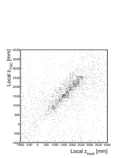
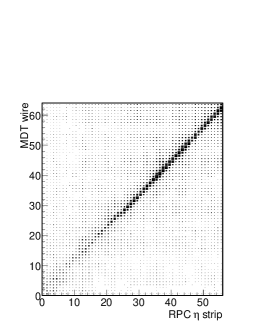
The two scatter plots in Fig. 1 show the correlation between hits in the trigger and in the precision tracking chambers. In the left plot, the hit position in , a local coordinate in a TGC chamber perpendicular to the TGC wires, is plotted versus the extrapolation to the position of the TGC chamber of a muon segment which is fit utilizing MDT hits only. It is easier to show a correlation between MDT and RPC hits because the geometry of the precision and trigger chambers overlap in the barrel region. It is thus enough to plot the correlation between readout channel numbers in MDT and in RPC chambers, after a trivial correction for different mappings. The correlation is shown in the central scatter plot in Fig. 1 for a barrel chamber in the MDT outer layer. Remarkably, no clean-up cuts have been applied to produce the distribution shown.
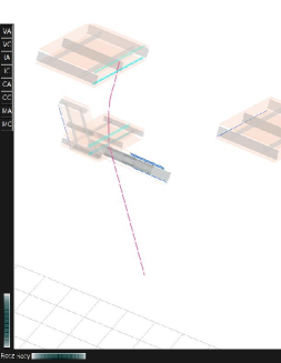
An event display from a run taken with the barrel toroid on at full current is presented in Fig. 1. The muon software reconstructs a track, which crosses two RPC chambers and three MDT chambers in the barrel region.
V SUMMARY
After the completion of hardware installations and connection to services, the ATLAS muons spectrometer is quickly reaching the fully-commissioned status. All subdetectors that compose the muon spectrometer achieved their design performance, for all the quantities that could be checked. Results from the most recent cosmics runs with and without the toroidal field have been presented. The collaboration is eagerly waiting for physics collisions, scheduled for spring 2009.
Acknowledgements.
We are greatly indebted to all CERN’s departments and to the LHC project for their immense efforts. We are grateful to all the funding agencies which supported the construction and the commissioning of the ATLAS detector and also provided the computing infrastructure.References
- (1) G. Aad et al. [ATLAS Collaboration], “The ATLAS Experiment at the CERN Large Hadron Collider,” JINST 3, S08003 (2008)
- (2) I.G. Eschrich, “Readout Electronics of the ATLAS Cathode Strip Chambers,” TWEPP-08, Naxos, September 13-19, 2008.
- (3) A. Barriuso Poy et al., “The detector control system of the ATLAS experiment,” JINST 3, P05006 (2008).