Further author information: (Send correspondence to Fabio Muleri)
Fabio Muleri: E-mail: Fabio.Muleri@iasf-roma.inaf.it,
Telephone: +39-0649934565
A versatile facility for the calibration of X-ray polarimeters with polarized and unpolarized controlled beams
Abstract
We devised and built a versatile facility for the calibration of the next generation X-ray polarimeters with unpolarized and polarized radiation. The former is produced at 5.9 keV by means of a Fe55 radioactive source or by X-ray tubes, while the latter is obtained by Bragg diffraction at nearly 45 degrees. Crystals tuned with the emission lines of X-ray tubes with molybdenum, rhodium, calcium and titanium anodes are employed for the efficient production of highly polarized photons at 2.29, 2.69, 3.69 and 4.51 keV respectively. Moreover the continuum emission is exploited for the production of polarized photons at 1.65 keV and 2.04 keV and at energies corresponding to the higher orders of diffraction. The photons are collimated by means of interchangeable capillary plates and diaphragms, allowing a trade-off between collimation and high fluxes. The direction of the beam is accurately arranged by means of high precision motorized stages, controlled via computer so that long and automatic measurements can be done. Selecting the direction of polarization and the incidence point we can map the response of imaging devices to both polarized and unpolarized radiation. Changing the inclination of the beam we can study the systematic effects due to the focusing of grazing incidence optics and the feasibility of instruments with large field of view.
keywords:
X-ray polarimetry, Bragg diffraction, calibration1 Introduction
The continuous development of new polarimeters based on the photoelectric effects has recently renewed the interest in the study of polarization from astrophysical sources in the X-ray band. The Gas Pixel Detector, developed by the INFN of Pisa[1, 2, 3], is one of the most advanced project in this field. It allows a large increase of sensibility with respect to the previous instruments, based on Bragg diffraction or Thomson scattering, and makes feasible the development of the X-ray polarimetry of astrophysical sources, for the first time after the pioneer experiments in the ’70.
The current version of the GPD works between 2 and 10 keV, with a sensitivity peaking at about 3 keV. Its response has been studied by employing a Monte Carlo software, while its calibration was at first attained with a polarized source based on Thomson scattering at nearly 90 degrees on a lithium target, enclosed in beryllium to prevent its oxidation and nitridation. However, such a Thomson scattering source doesn’t allow the production of photons below about 5 keV, i.e. in the range of maximum sensitivity of the GPD, because of the photoelectric absorption in the target.
The construction by IASF/INAF of Rome of a very compact X-ray polarized source, based on the Bragg diffraction at nearly 45 degrees [4], has eventually overcome this problem and allowed for the first time the measurement of the sensibility of the GPD at low energy. We employed mosaic graphite and flat aluminum crystals to produce nearly completely polarized photons at 2.6, 3.7, and 5.2 keV from the diffraction of unpolarized continuum or line emission. These measurements have been proved that the GPD responds as expected on the basis of a Monte Carlo software [5].
The next step in the characterization of the GPD is then the systematic study of its response with a space-controlled polarized beam, with energies covering the whole response of the instruments. Here we present the facility we devised and built at this aim.
2 The production of highly polarized photons
2.1 The Bragg Diffraction
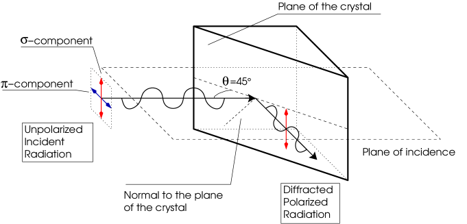
Low energy and polarized photons can be produced by means of Bragg diffraction at nearly 45 degrees. If is the diffracted intensity when parallel monochromatic radiation of unit intensity and energy is incident at glancing angle to the diffracting planes of a flat crystal, the integrated reflectivity is defined as [6]:
| (1) |
The integrated reflectivity expresses the “efficiency” of the diffraction and is sensitive to the polarization of the incident radiation. If we define the ratio of the integrated reflectivity for radiation polarized parallel (-component) and perpendicularly (-component) to the incidence plane, depends on the diffraction angle and is generally lower than 1 (see Fig. 1). The radiation perpendicularly polarized to the incidence plane is then diffracted more efficiently and the net effect is that the diffracted radiation is partially polarized perpendicularly to the plane of incidence, independently to the polarization state of the incident photons. The degree of polarization is [6]:
| (2) |
In Fig. 2(a) we report the ratio for the diffraction on the plane 002 of a fluorite crystal (CaF2), calculated by Henke et al.[7]. For , and, according to Eq. 2, the degree of polarization , as shown in Fig. 2(b). Then the radiation is almost completely polarized when the diffraction angle is constrained to nearly 45∘. Moreover, the diffracted photons must satisfy, within some eV for flat crystals, the Bragg condition:
| (3) |
where and are respectively Planck’s constant and the speed of light, the crystal lattice spacing and the diffraction order. Hence, by constraining , the spectrum is composed of equally spaced, nearly monochromatic and polarized lines corresponding to the various orders of diffraction . Moreover, the choice of crystals with different lattice spacing allows the production of lines at different energies.
If continuum radiation is diffracted, the quick change of with the diffraction angle can reduce the mean polarization of output radiation, since photons at slightly different energies are diffracted at angles (and then with polarization) slightly different. Hence, very tight limits around must be set with a collimator. However this limits the flux, since in this case the diffracted photons must have an energy centered at the Bragg energy more or less some tens of eV. A trade-off between the degree of polarization and reasonable fluxes can be then achieved by choosing the degree of collimation.
Conversely, if line emission at energy close to the Bragg energy is employed, line photons are diffracted with an efficiency of about 50%, with a small contribution from the continuum photons that can be generally neglected. Hence the precise diffraction angle, and consequently the degree of polarization, can be easily derived from Eq. 3 and Eq. 2 respectively, thanks to the knowledge of the energy of incoming line photons.


2.2 The source
A source based on the Bragg diffraction was already presented by Muleri et al.[4]. Here we present an improved version of that first prototype, with which we are able to produce polarized photons starting at 1.6 keV with by far higher fluxes by exploiting medium-power X-ray tubes and new crystals.
The improved version of the source shares the same base-design as the prototype. Lead-glass capillary plates are used to collimate X-rays, since their 10 m diameter holes, organized in a hexagonal pattern with an on-axis transparency of 57%, allow good collimation with limited size. Semi-collimations of and are achieved by means of capillary plates 0.4 and 1.0 mm thick, with an effective diameter of 20 and 27 mm respectively. The type and the number of capillary plates (one or two, to constrain only the input or output radiation or both) are chosen to achieve a trade-off between reasonable fluxes and high degree of polarization.
Unpolarized X-rays are produced by commercial tubes with a maximum power of 50 W, manufactured by Oxford Instruments. Three different tubes, with anode of molybdenum, rhodium and titanium, are employed to produce line emission at 2.29, 2.69 and 4.51 keV respectively. These energies are in accordance with the 45∘ Bragg diffraction from rhodium (001), germanium (111) and fluorite (CaF2, 220) crystals [7]. Moreover, an ADP (101) and a PET (002) crystals are employed to produce polarized emission at 1.65 and 2.04 keV by means of diffraction of continuum radiation. In the table 1 the properties of the X-ray tubes and of the crystals available in our facility are summarized.
| Incident radiation (X-ray tube) | Energy (keV) | Crystal | ||
|---|---|---|---|---|
| Continuum | 1.65 | ADP (NH4H2PO4, 101) | 45∘ | 1.0 |
| Continuum | 2.04 | PET (CCH2OH, 002) | 45∘ | 1.0 |
| L Molybdenum (50 W) | 2.293 | Rhodium (001) | 45.36∘ | 0.9994 |
| Continuum | 2.61 | Graphite (002) | 45∘ | 1.0 |
| L Rhodium (50 W) | 2.691 | Germanium (111) | 44.86∘ | 0.9926 |
| K Calcium (200 mW) | 3.692 | Aluminum (111) | 45.88∘ | 0.9938 |
| K Titanium (50 W) | 4.511 | Fluorite CaF2 (220) | 45.37∘ | 0.9994 |
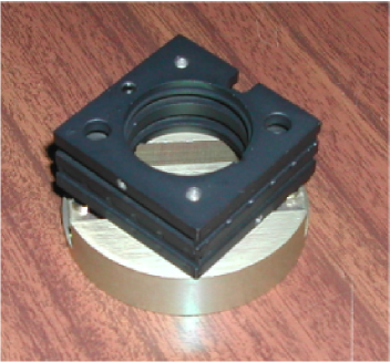
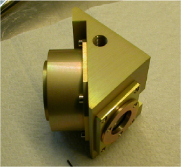
Since the choice of the diffracting crystal allows to produce polarized radiation at different energies, we mounted each crystal in a different aluminum case to easily manage and change them. An important difference between the prototype and the improved version of the source is that in the latter we mounted each crystal case on a manual stage which allows two axes tilt regulation in the range (see Fig. 3(a)). The stage is then mounted on a central body (see Fig. 3(b)) and it is regulated to achieve the best alignment to the Bragg condition by means of optical and X-ray measurements. In the first case, a mirror mounted on the case of the crystal is employed to reach the optimum angle between the crystal and the collimators, which are partially reflective. Then the inclination is refined with X-ray measurement to reach the highest flux.
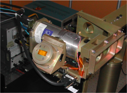
We added two standard gas connectors in the central body (see Fig. 5) on the top and bottom side of the source for helium flowing to reduce air absorption which heavily affects low energy photons. For the same reason, we reduced to the minimum the path of the photons.
The collimators also are mounted on an aluminum case, since their choice allows to achieve a trade-off between high fluxes and clean spectra. Two issues can indeed detach the output radiation from the ideal condition of monochromatic and highly polarized photons. The first one is that radiation can be scattered at nearly 90∘ on the crystal or on its case and then photons not at the Bragg energy can emerge from the source. The second issue is that the input radiation is partially absorbed in the crystal (and in the aluminum case) and then unpolarized fluorescence emission is produced. This problem is especially important when 1.65 keV polarized photons are produced, since the aluminum K fluorescence is at 1.5 keV, and with the fluorite crystal, since the 3.7 K fluorescence of calcium has a comparable energy (and hence absorption) with respect to the polarized photons at 4.5 keV produced with diffraction on that crystal.
The flux of fluorescence and of the scattered radiation can be reduced with respect to the polarized one by means of narrower collimators, which reduce the incident flux but save the Bragg condition for diffraction. Indeed the first two components are approximately proportional to the incident radiation, while the latter depends only on the flux of the line emission. For example, in Fig. 4 we report the spectra from the diffraction of emission of the tube with titanium anode on the fluorite crystal with different configurations of collimators, while the ratio between the fluxes of the polarized line and that of the fluorescence of calcium at 3.7 keV is reported in Table 2.


| Input collimator | Output collimator | Fluxpolarized (c/s) | Fluxfluorescence (c/s) | Ratio |
|---|---|---|---|---|
| — | 1073.73.0 | 18.040.47 | 60 | |
| 458.380.79 | 1.0460.072 | 440 |
The complete source, composed by the polarizer and the X-ray tube, is shown in Fig. 5 mounted on the mechanical assembly described in Sec. 3. The cooling of the tube is performed with four fans and, if its temperature increases above a determined threshold, it is turned off.
We have focused our attention to the first order of diffraction, since in this case the line emission of the tubes is in accordance with the diffraction at nearly 45∘. However the continuum radiation produced by the X-ray tube by bremsstrahlung can be employed to produce also high energy and polarized radiation exploiting higher orders of diffraction, i.e. at energies which are integer multiple of the energy of the first order (see Table 1). The medium power X-ray tubes can be very efficiently employed at this aim, since the high voltage (and hence the maximum energy of the photons produced) can be controlled independently from the current (and hence from the flux of the photons). Then, to produce polarized photons at 9 keV exploiting the second order of diffraction from fluorite, we can set the high voltage at 13 kV, i.e. just below the energy of the third order of diffraction, and then change the current to increase the flux up to 1 mA.
In Fig. 6 we show the spectrum obtained with diffraction of continuum radiation on the PET crystal. The first five orders are visible with a relative peak heights which depend mainly on the different efficiency of the diffraction for each order and on the spectrum of the unpolarized incident radiation. Helium flowing was employed to avoid absorption of low energy photons. The rate of the lines are reported in Table 3.

| Flux (c/s) | Flux (c/s) | ||
|---|---|---|---|
| 2.04 keV - I order | 224.01.5 | 8.16 keV - IV order | 13.440.43 |
| 4.08 keV - II order | 73.51.0 | 10.20 keV - V order | 7.410.27 |
| 6.12 keV - III order | 17.100.39 |
3 The mechanical assembly
The polarized source described in Sec. 2.2 allows to overcome the problem of the measurement of the low energy performances of the GPD, since photons with energy as low as 1.65 keV can be produced. The next improvement is then a systematic study of the sensibility of the GPD with a space-controlled beam. In particular, we want to explore:
-
•
the response on all the surface of the detector, since the GPD can also perform imaging on extended sources (XY-mapping);
-
•
the correlation between the direction and the reconstructed angle of polarization (angle reconstruction);
-
•
the study of the response to inclined beams, due to the focusing of grazing incidence optics or to large field of view instruments (inclined measurements).
We employed the Bragg diffraction sources described above and high precision motorized stages, manufactured by Newport, to built a facility to perform these tasks. In addition to the Bragg sources (the prototype and the improved version), we interfaced even unpolarized sources with the facility. In summary, we can produce:
-
•
a collimated and, in case, diaphragmed polarized and nearly monochromatic beam, produced by means of Bragg diffraction. We can employ the prototype source at 3.7 keV or the improved version at 1.65, 2.04, 2.29, 2.69 and 4.51 keV. The higher orders of diffraction are also available.
-
•
collimated and/or diaphragmed unpolarized radiation at 5.89 and 6.49 keV by means of a Fe55 radioactive source.
-
•
collimated and/or diaphragmed unpolarized radiation at about 2.29, 2.69, 4.51 keV by means of direct emission from X-ray tubes.
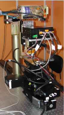
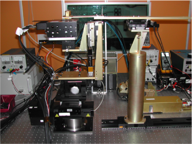
The mechanical assembly is designed to perform automatically and subsequently the measurements listed above, i.e. XY-mapping, angle reconstruction and inclined measurements, for each source. The detector is mounted on a platform which can be rotated, inclined and moved with respect to the beam with eight motorized stages and two manual ones. Moreover, the source is mounted on a rail with a graduated scale which allows its quick movement when maintenance operations are performed on the tower supporting the detector (see fig. 7). The facility is mounted on an optical table in a room, shielded by X-ray radiation with a 1 mm of lead.
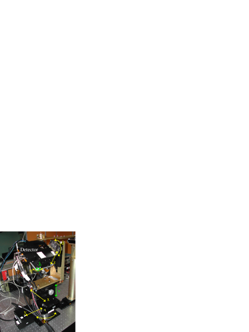
The stages are divided into two groups. The first one includes five motorized stages which actually change the direction of the detector with respect to the beam, while the second group is employed to align the beam with the detector. In the former group there are (see fig. 8):
-
1.
(inclination angle, resolution 1”): The main purpose of this stage is to allow the inclination of the detector at large angles, typically between +60 and -60 degrees. Moreover it is employed with to automatically adjust the tilt angle of the detector, i.e. to align the detector orthogonally to the incoming beam.
-
2.
(polarization angle, resolution 0.2”): This stage allows to change the direction of polarization of the beam. The range is between 0 and 360∘. A dedicated control has been implemented in the software to prevent the twisting of the cables.
-
3.
: (resolution 0.5 m) This stage allows the XY mapping together with . Moreover it is employed to center the detector with the beam.
-
4.
: (resolution 0.5 m) The role of this stage is complementary to .
-
5.
: This stage is employed to adjust the distance between the detector and the source. While, at low energy, the beam is heavily affected by air absorption and so the distance from the source must be reduced, during the measurements at large angles of inclination the detector should be placed on the rotation axis of , to prevent the movement of the detector with the increasing of the inclination angle. Hence this stage for all practical purposes has two positions, Up when the distance from the source is reduced, and Down when the axis of rotation of the inclination crosses the detector.
The stages which instead are employed to align the detector with the beam are:
-
6.
: This motorized stage allows to tilt the plane of the detector to align it orthogonally to the incoming beam.
-
7.
(resolution 0.1 m): The purpose of this motorized stage is to center, together with , the beam with the axis of rotation of the stage . This allows to study how the angle of polarization is measured in each region of the detector and if systematic effects exist.
-
8.
(resolution 0.1 m): The role of this motorized stage is complementary to .
-
9.
: This stage allows a manual tilt regulation of the plane of the detector. For all practical purposes this stage is redundant with respect to .
-
10.
: The rail which allows the quick movement of the source when maintenance operation are performed on the tower. The rail is provided with a graduated scale with 1 mm pitch.
-
—.
: A further stage allows a vertical adjustment with a range of about 44 mm.
Hence, a total of ten stages are employed to align and control the beam. All the motorized ones are connected to a controller, which in its turn is connected with a PC by means of an ethernet cable. The motorized stages can be manually moved with a remote control or by means of a web interface of the controller.
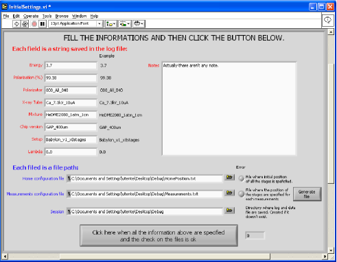
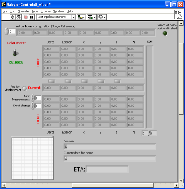
The movements of the facility and the acquisition of the GPD are controlled by means of a LabView software, which can manage all kind of studies quoted above to perform long-lasting sessions of sequentially measurements, without the presence of the user. The control program is organized into two steps. All the informations required to the session of measurements are collected in the first one (see Fig. 9(a)), after that a second panel reports the current measurement and the progress of the session (see fig. 9(b)). The positions of all stages are saved in a log and in the data file for subsequent automatic analyzes.
4 Preliminary results
A test of the facility was performed by using an Amptek XR100CR Si-PIN detector to map the 3.7 keV K calcium line diffracted by the aluminum crystal. A diaphragm of 1 mm is used in front of the detector to sample the beam.
In Fig. 10 the map of the rate of the flux is shown on a grid of 75 points. The beam is elliptical, with a major axis (in the direction of polarization) of about 4 mm FWHM. In the perpendicular direction, the extension of the beam is 2 mm FWHM. Since the diffraction should not change the section of the beam, it should reflect the shape of cathode of the X-ray tube.
The properties of the line are identical for all the central 73 points, where the counts are sufficient for a reliable fit. In Fig. 11(a) we report the FWHM of the line for the 73 measurements, which are clearly consistent within errors. In the Fig. 11(b) instead, the energy of the line is shown. In this case a increasing trend is present, even if it can be imputed to changes in the silicon detector, since it follows the sequence in which the measurements were done.


5 Conclusion
We have designed and built a facility for the calibration of the next generation X-ray polarimeters. Polarized photons are produced by means of Bragg diffraction at nearly 45 degrees. Following the good results of a prototype source which allows the diffraction of continuum or line emission on aluminum or graphite crystals[4], we have developed an improved version of the source which can exploit also the diffraction on ADP, PET, rhodium, germanium and fluorite crystals. Thanks to X-ray tubes with anodes tuned with these crystals, we can very efficiently produce almost completely polarized photons at 2.29, 2.69 and 4.51 keV. Moreover, continuum emission is employed to generate highly polarized radiation at 1.65 and 2.04 keV. Both the prototype and the improved version of the polarized sources have been interfaced, together with unpolarized sources, with a mechanical assembly which, thanks to motorized stages controlled via PC, allows calibration measurements with space-controlled beams. In particular the facility is optimized for mapping the response of imaging devices to both polarized and unpolarized radiation, with inclined or orthogonal beams. This facility will be soon employed for the calibration of the Gas Pixel Detector.
Acknowledgments
FM acknowledges financial support from Agenzia Spaziale Italiana (ASI) under contract ASI I/088/06/0.
References
- [1] Costa, E., Soffitta, P., Bellazzini, R., Brez, A., Lumb, N., and Spandre, G., “An efficient photoelectric X-ray polarimeter for the study of black holes and neutron stars,” Nature 411, 662–665 (2001).
- [2] Bellazzini, R., Spandre, G., Minuti, M., Baldini, L., Brez, A., Cavalca, F., Latronico, L., Omodei, N., Massai, M. M., Sgro’, C., Costa, E., Soffitta, P., Krummenacher, F., and de Oliveira, R., “Direct reading of charge multipliers with a self-triggering CMOS analog chip with 105 k pixels at 50 m pitch,” Nuclear Instruments and Methods in Physics Research A 566, 552–562 (2006).
- [3] Bellazzini, R., Spandre, G., Minuti, M., Baldini, L., Brez, A., Latronico, L., Omodei, N., Razzano, M., Massai, M. M., Pesce-Rollins, M., Sgró, C., Costa, E., Soffitta, P., Sipila, H., and Lempinen, E., “A sealed Gas Pixel Detector for X-ray astronomy,” Nuclear Instruments and Methods in Physics Research A 579, 853–858 (2007).
- [4] Muleri, F., Soffitta, P., Bellazzini, R., Brez, A., Costa, E., Fabiani, S., Frutti, M., Minuti, M., Negri, M. B., Pascale, P., Rubini, A., Sindoni, G., and Spandre, G., “A very compact polarizer for an X-ray polarimeter calibration,” in [Proc. SPIE ], 6686, 668610 (2007).
- [5] Muleri, F., Soffitta, P., Baldini, L., Bellazzini, R., Bregeon, J., Brez, A., Costa, E., Frutti, M., Latronico, L., Minuti, M., Negri, M. B., Omodei, N., Pesce-Rollins, M., Pinchera, M., Razzano, M., Rubini, A., Sgró, C., and Spandre, G., “Low energy polarization sensitivity of the Gas Pixel Detector,” Nuclear Instruments and Methods in Physics Research A 584, 149–159 (2008).
- [6] Evans, K. D., Hall, R., and Lewis, M., “The calibration of Bragg X-ray analyser crystals for use as polarimeters in X-ray astronomy.,” Space Science Instrumentation 3, 163–169 (1977).
- [7] Henke, B. L., Gullikson, E. M., and Davis, J. C., “X-Ray Interactions: Photoabsorption, Scattering, Transmission, and Reflection at E = 50-30,000 eV, Z = 1-92,” Atomic Data and Nuclear Data Tables 54, 181 (1993).