Cancellation of nonlinear Zeeman shifts with light shifts
Abstract
Nonlinear Zeeman (NLZ) shifts arising from magnetic-field mixing of the two hyperfine ground-states in alkali atoms lead to splitting of magnetic-resonance lines. This is a major source of sensitivity degradation and the so-called “heading errors” of alkali-vapor atomic magnetometers operating in the geophysical field range ( G). Here, it is shown theoretically and experimentally that NLZ shifts can be effectively canceled by light shifts caused by a laser field of appropriate intensity, polarization and frequency, a technique that can be readily applied in practical situations.
pacs:
PACS. 07.55.Ge, 32.60.+i, 42.65.-kI Introduction
Alkali-vapor atomic magnetometers Budker and Romalis (2007) operating in the geophysical range of magnetic fields, where the Zeeman effect is very close to linear, are nevertheless quite sensitive to the nonlinear corrections to the Zeeman effect (NLZ) which cause broadening and splitting of the magnetic-resonance lines, as well as line-shape asymmetries that depend on the orientation of the sensor with respect to the field Acosta et al. (2006); Seltzer et al. (2007). Thus, NLZ is responsible for sensitivity degradation and systematic (heading) errors in atomic magnetometers Alexandrov (2003); Roc . Recently, collapse and revival of ground-state quantum beats associated with NLZ was studied theoretically Alexandrov et al. (2005) and experimentally Seltzer et al. (2007), and a scheme for mitigating the effects of NLZ in an atomic magnetometer based on double-modulated synchronous optical pumping was realized Seltzer et al. (2007). Alternative approaches explored recently include the use of multi-quantum transitions and high-order atomic polarization moments Alexandrov et al. (1997); Okunevich (2001); Acosta et al. (2008); Yashchuk et al. (2003). Here, we introduce an alternative technique where NLZ shifts are compensated by light shifts due to an additional light field of appropriate intensity, polarization and frequency, which is possible due to the identical tensor structure of the splitting caused by the two effects. The present technique is free from some shortcomings of the alternative techniques such as complexity of implementation and/or degradation of the signal. Moreover, in contrast to the double-modulated synchronous pumping technique of Ref. Seltzer et al. (2007), the present approach works well when the ground-state polarization-decay rate approaches the NLZ frequency splitting (a common situation for practically important Rb and Cs magnetometers).
Compensation of NLZ with AC Stark shifts was recently investigated in the field of quantum information, theoretically as part of a quantum memory protocol Opatrný (2006) and experimentally for improving atomic spin-squeezing Fernholz et al. (2008). The similarities of light shifts and Zeeman shifts was used in Refs. Park et al. (2002); Vengalattore et al. (2007), where magnetic fields were simulated by light fields. It has also been proposed to use light shifts to measure parity violation in Fr atoms Bouchiat (2008). In general, light shifts are important in precision measurements in atomic physics, for instance in atomic clock experiments, where one can use the famous “magic wavelengths” to eliminate light shifts, see for example Refs. Jun et al. (2008); Flambaum et al. (2008) and references therein.
II Theory
For an alkali atom with nuclear spin , total angular momentum and projection of the total angular momentum on the direction of the magnetic field, the Zeeman energies of the magnetic sublevels are to second order in the field given by
| (1) |
where is the Bohr magneton, is the hyperfine interval, and we neglect small corrections proportional to the nuclear magneton and the anomalous magnetic moment of the electron. The first-order shift leads to precession of the atomic polarization around the magnetic field with Larmor frequency , while the second-order shift leads to splitting of the magnetic resonances. For the hyperfine manifold of 87Rb, there are three resonances with adjacent-frequency splittting
| (2) |
For 87Rb atoms placed in a magnetic field of 0.5 G, we have kHz and Hz.
Consider now 87Rb atoms illuminated with linearly polarized light near-resonant with the D1 transition. Based on the calculations in Refs. Happer and Mathur (1967); Mathur et al. (1968) we can find analytical results for the AC Stark shifts of the energy levels in the ground-state manifold. For light polarized along the magnetic field, we find a change in the splitting of adjacent resonance frequencies of
| (3) |
where is the permittivity of vacuum, is the excited-state hyperfine-structure coefficient measured in Hz, is the natural linewidth of the excited state, is the transition wavelength, is the electric field amplitude of the light and the light frequency detuning is measured relative to the transition and assumed to be much larger than the Doppler width and the upper-state hyperfine interval. For light polarized transverse to the magnetic field, we find that the change in splitting of the resonances are of half the magnitude and of the opposite sign compared to the longitudinal case. In general, if the L2 light is linearly polarized at an angle to the magnetic field, the differential shifts of the sublevels are proportional to , see, for example, Problem 2.11 in Ref. Budker et al. (2008). Since the splitting increases in response to light of transverse polarization and decreases in response to longitudinal polarization, NLZ can only be compensated on this transition using longitudinal polarization. Using Eqs. (2) and (3) we can calculate the D1 light power needed to cancel the nonlinear Zeeman effect, and we find
| (4) |
Here we asssume that the atoms are kept in a cylindrical cell of diameter , and that the average light intensity , where is the speed of light in vacuum, determines the amount of compensation. This is the case for atoms in an antirelaxation-coated cell, where each atom samples the light field in the entire cell volume. Similar calculations for light near-resonant with the D2 transition shows that the change in splitting is of the opposite sign compared to the D1 case, and that roughly 8-10 times more power is needed to cancel NLZ.
In addition to shifting the magnetic resonances, light also broadens them. One source of this broadening is absorption of light by the ground-state atoms. The broadening depends on the light power needed to compensate NLZ. For large detunings the broadening at the compensation power will be independent of detuning, since the power needed to cancel NLZ goes as and the absorption rate goes as . Based on the calculations in Refs. Happer and Mathur (1967); Mathur et al. (1968), we find the broadening at the compensation power for D1 light with longitudinal polarization to be
| (5) |
For D2 light with transverse polarization we find that the broadening at the compensation power is around 20 times larger compared to the D1 case. It will therefore be preferable to use D1 light to cancel NLZ.
Another source of light broadening results from the nonuniform intensity profile of the light beam over the cross-sectional area of the cell. If, as in our case, the compensating light illuminates only a small portion of the cell, the atoms are subject to short periods of compensating light at random intervals, so that the phase of each atom’s evolution undergoes a random walk. This leads to dephasing of the atomic evolution at a rate , where is the phase shift an atom experiences in each pulse of compensating light, and is the average time between pulses. In order that the light properly compensates the nonlinear Zeeman effect, we must have . The average time for an atom to cross the cell is on the order of , where is the rms atomic velocity, and the probability that an atom passes through the light beam in one trip across the cell is on the order of , where is the beam diameter, so . Thus
| (6) |
By inserting typical experimental values ( G, cm and mm), we find Hz and Hz, and we see that dephasing dominates the broadening.

III Experimental setup, procedure and results
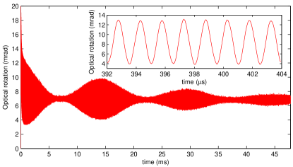
Figure 1 shows the experimental setup. A paraffin-coated cylindrical glass cell (with diameter and length of 2 cm) at room temperature containing 87Rb is located within a multi-layer magnetic shield with a system of coils in the inner volume designed to produce a homogeneous Earth-range magnetic field along the direction. The atoms in the ground-state are optically pumped and probed using a beam from a diode laser (L1) with frequency close to either the D1 or D2 line. The intensity of the light is modulated with an acousto-optical modulator (AOM). The same laser beam, initially linearly polarized in the direction, is used to create atomic alignment (the rank-two atomic polarization that is characterized by a preferred “alignment axis”) and to probe the alignment via optical rotation due to the polarized atoms Gawlik et al. (2006). A measurement consists of two consecutive stages. During the first, pumping stage, the laser intensity is square-wave modulated (duty cycle 1/8) at a rate equal to twice the Larmor frequency, and ground-state atomic alignment is synchronously pumped for ms. The beam diameter is mm, and the power during the “on” part of the cycle is mW. Once the atoms are pumped, the AOM is set to transmit around W of light, which probes the atomic alignment created during the pumping stage. The optical rotation of the transmitted light is measured by a balanced polarimeter. An example of a free-induction decay (FID) signal (averaged over 1024 cycles) is shown in Fig. 2. The FID signal oscillates at 667 kHz (see inset) corresponding to twice the Larmor frequency. The NLZ-induced beats in the signal are observed as a change in the oscillation amplitude with time. The signal has an offset of around 7 mrad due to imperfect balancing of the polarimeter.
We model the measured FID signals with a function of the form
| (7) | |||||
which consists of a central component of amplitude oscillating at twice the Larmor frequency and two sidebands with frequencies of equal amplitude and opposite phase . The three frequency components decay with time, and for simplicity it is assumed that the decay time is the same for all three components. We analyze the envelope of the signal by postprocessing the data with a digital lock-in amplifier with reference frequency . The envelope can be calculated from Eq. (7) and we find
| (8) | |||||
It is found experimentally that the demodulated FID signals are well described by Eq. (8). For the data presented in Fig. 2, a fit of the envelope to Eq. (8) gives the value of Hz, consistent with the expected value due to the NLZ effect for the magnetic field of G used for the data presented in Fig. 2. The overall decay time extracted from the fit is ms, limited by magnetic-field gradients and drifts in the bias magnetic field combined with signal averaging [for comparison, at lower magnetic field of 24 mG the relaxation time was measured to be ms].
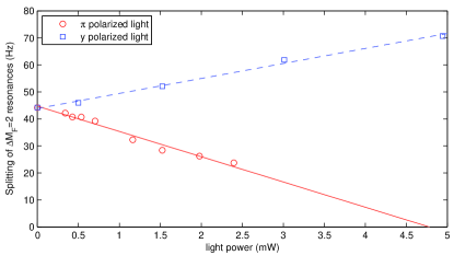

In order to cancel NLZ, linearly polarized light from a second diode laser (L2) tuned close to the D1 resonance was directed through the vapor cell along the direction. The splitting of the resonances was measured as described above for different detunings, polarizations and powers of the L2 light. Figure 3 shows the splitting as a function of light power inside the cell for two polarizations, along and transverse to the magnetic field (denoted and polarization in the figure), for a detuning GHz from the D1 transition. The splittings were fit to straight lines yielding the slopes Hz/mW and Hz/mW, which within the uncertainties confirms that the light shifts due to polarized light have the opposite sign and are of half the magnitude compared to the light shifts due to polarized light. It should be noted that when the splitting is smaller than the linewidth of the resonances, it is difficult to extract the splitting from the FID signal. Therefore, in order to find the light power where the light shifts cancel NLZ, an extrapolation from the linear fit was used. In Fig. 3 the light power where the splitting is zero is mW.
Figure 4 (solid line) shows the power spectrum of a FID signal with the L2 light blocked. Three resonances are seen, split from each other in frequency due to NLZ. When the L2 light is on (dashed line), with the appropriate power needed to cancel NLZ, the peaks are combined into a single, stronger resonance. However, the L2 light also broadens the resonance. The FWHM of the resonances are 14.0(4) Hz (solid line) and 27.8(4) Hz (dashed line), giving a broadening of 13.8(6) Hz due to L2 light. By comparing the two spectra in Fig. 4, it is seen that there is a shift of Hz in the central frequency of the resonances. The shift is not thought to be due to the L2 light, but instead due to drifts in the current supply for the bias magnetic field in between the two measurements.

The L2 light power needed to cancel the NLZ effect was measured for different frequencies of the L2 light close to the D1 resonance; the results are plotted in Fig. 5 (top). For these measurements, the magnetic field was set to G, producing a NLZ shift Hz. Also plotted in Fig. 5 (top) is the theoretical calculation for the compensation power given by Eq. (4), showing a reasonable agreement between theory and experiment. The broadening of the magnetic resonance due to the L2 light at the compensation power was also measured and is plotted in Fig. 5 (bottom) together with the estimated broadening due to dephasing. In the frequency range within -4 to 5 GHz of the D1 transition the broadening is approximately constant and consistent with the dephasing estimate. For the detuning GHz (which is on the resonance) a slightly larger broadening was measured. We note that the broadening due to dephasing can be avoided if the compensating light has a homegeneous intensity profile over the cell volume. In the experiment the beam diameter of the compensating light was rather small, and we therefore expect that it is possible to significantly reduce the broadening by for instance expanding the beam.
IV Discussion and Conclusions
To be useful in practical magnetometers, our method for compensating NLZ should be robust against, for instance, intensity fluctuations of the L2 laser light. At Earth-range magnetic fields, NLZ splits the magnetic resonances considered in the experiment by approximately 70 Hz. We compensate NLZ by overlapping the resonances. The resonances will overlap if they are positioned within their width, which in our particular case is around 30 Hz (see Fig. 4). Since the splitting between the resonances is linear in L2 laser intensity, the relative intensity noise of the laser should be (much) less than the ratio of the linewidth to the splitting without compensation, in this case 30 Hz / 70 Hz 40 %. In practical situations one can easily stabilize lasers to have less than 1 % intensity noise. The intensity noise has therefore very little effect on the compensation. Similarly, we estimate that the frequency drifts of the L2 laser within easily achievable MHz lead to sub-1-% changes in the induced light shifts, much smaller than typical resonance width.
In conclusion, using AC Stark shifts, we compensated the nonlinear Zeeman effect for 87Rb atoms located in a magnetic field comparable to the Earth’s magnetic field. The method can directly be applied to alkali-vapor atomic magnetometers in order to reduce heading errors and increase sensitivity.
ACKNOWLEDGMENTS
The authors are grateful to E. S. Polzik for encouragement and support, to W. Gawlik for comments on the manuscript and to E. Corsini for helpful discussions. This work has been supported by NURI grant HM1582-08-1-0006, ONR MURI and STTR grants.
References
- Budker and Romalis (2007) D. Budker and M. V. Romalis, Nature Physics 3, 227 (2007).
- Acosta et al. (2006) V. Acosta, M. P. Ledbetter, S. M. Rochester, D. Budker, D. F. Jackson Kimball, D. C. Hovde, W. Gawlik, S. Pustelny, J. Zachorowski, and V. V. Yashchuk, Phys. Rev. A 73, 053404 (2006).
- Seltzer et al. (2007) S. J. Seltzer, P. J. Meares, and M. V. Romalis, Phys. Rev. A 75, 051407(R) (2007).
- Alexandrov (2003) E. B. Alexandrov, Physica Scripta T105, 27 (2003).
- (5) Unpublished results by S. M. Rochester, J. Higbie and D. Budker show that heading errors are of less importance for alignment-based magnetometers compared to the traditional orientation-based alkali-vapor magnetometers.
- Alexandrov et al. (2005) E. B. Alexandrov, M. Auzinsh, D. Budker, D. F. Kimball, S. M. Rochester, and V. V. Yashchuk, J. Opt. Soc. Am. B 22, 7 (2005).
- Alexandrov et al. (1997) E. B. Alexandrov, A. S. Pazgalev, and J. L. Rasson, Optika i Spektroskopiya 82, 14 (1997).
- Okunevich (2001) A. I. Okunevich, Optika i Spektroskopiya 91, 193 (2001).
- Acosta et al. (2008) V. M. Acosta, M. Auzinsh, W. Gawlik, P. Grisins, J. M. Higbie, D. F. J. Kimball, L. Krzemien, M. P. Ledbetter, S. Pustelny, S. M. Rochester, et al., Optics Express 16, 11423 (2008).
- Yashchuk et al. (2003) V. V. Yashchuk, D. Budker, W. Gawlik, D. F. Kimball, Y. P. Malakyan, and S. M. Rochester, Phys. Rev. Lett. 90, 253001 (2003).
- Opatrný (2006) T. Opatrný, Phys. Rev. A 74, 043809 (2006).
- Fernholz et al. (2008) T. Fernholz, H. Krauter, K. Jensen, J. F. Sherson, A. S. Sørensen, and E. S. Polzik, Phys. Rev. Lett. 101, 073601 (2008).
- Park et al. (2002) C. Y. Park, J. Y. Kim, J. M. Song, and D. Cho, Phys. Rev. A 65, 033410 (2002).
- Vengalattore et al. (2007) M. Vengalattore, J. M. Higbie, S. R. Leslie, J. Guzman, L. E. Sadler, and D. M. Stamper-Kurn, Phys. Rev. Lett. 98, 200801 (2007).
- Bouchiat (2008) M. A. Bouchiat, Phys. Rev. Lett. 100, 123003 (2008).
- Jun et al. (2008) Y. Jun, H. J. Kimble, and H. Katori, Science 320, 1734 (2008).
- Flambaum et al. (2008) V. V. Flambaum, V. A. Dzuba, and A. Derevianko, Phys. Rev. Lett. 101, 220801 (2008).
- Happer and Mathur (1967) W. Happer and B. S. Mathur, Phys. Rev. 163, 12 (1967).
- Mathur et al. (1968) B. S. Mathur, M. Tang, and W. Happer, Phys. Rev. 171, 11 (1968).
- Budker et al. (2008) D. Budker, D. Kimball, and D. DeMille, Atomic physics An exploration through problems and solutions (Oxford University Press, 2008), 2nd ed.
- Gawlik et al. (2006) W. Gawlik, L. Krzemien, S. Pustelny, D. Sangla, J. Zachorowski, M. Graf, A. O. Sushkov, and D. Budker, Appl. Phys. Lett. 88, 131108 (2006).