Linearly polarised photon beams at ELSA
Abstract
At the electron accelerator ELSA a linearly polarised tagged photon beam is produced by coherent bremsstrahlung off a diamond crystal. Orientation and energy range of the linear polarisation can be deliberately chosen by accurate positioning of the crystal with a goniometer. The degree of polarisation is determined by the form of the scattered electron spectrum. Good agreement between experiment and expectations on basis of the experimental conditions is obtained. Polarisation degrees of Pγ= 40% are typically achieved at half of the primary electron energy. The determination of Pγ is confirmed by measuring the beam asymmetry, , in photoproduction and a comparison of the results to independent measurements using laser backscattering.
pacs:
13.60.-rPhoton and charged-lepton interactions with hadrons and 13.60.LeMeson production and 13.88.+ePolarization in interactions and scattering1 Introduction
Experiments based on photo-induced exclusive reactions
are well suited to improve our understanding of the complicated structure of
the nucleon. In addition to measurements of cross sections, polarisation observables
are indispensable. They are sensitive to interference terms and therefore give
access to small amplitudes, even if those are too small to affect the total cross
section significantly. Circularly and linearly polarised photon beams
allow, in combination with target or recoil polarisation, the extraction of double polarisation
observables. From linearly polarised photons alone the beam asymmetry,
, can be extracted (for a definition of the observables see e.g. ref. Knoechlein95 ).
In case of pseudoscalar meson photoproduction the beam asymmetry alone
does not allow an unambiguous extraction of all partial waves Elsner07 , but
its measurement is essential in view of a complete experiment CT97 .
The two common methods for generation of linearly polarised photons are
coherent bremsstrahlung and Compton backscattering (CBS).
In Compton backscattering the electron beam collides with a laser beam of
short wavelength. Linearly polarised photons can be produced using linearly polarised laser
photons Nakano01 ; GraalPi .
The degree of polarisation of the CBS photons is proportional to that of laser
photons, with its maximum at the highest photon energy. At the present
facilities this method is compared to electron bremsstrahlung limited in intensity and achievable maximum photon
energy.
In coherent electron bremsstrahlung the recoil is transferred to a crystal
radiator. Depending on its orientation relative to the electron beam, the whole crystal
absorbs the recoil, which fixes the plane of electron
deflection. Consequently, the photons produced by the coherent process are
linearly polarised. Compared to CBS, photon beams from coherent bremsstrahlung have a higher
intensity, but on the other hand a lower maximum degree of polarisation at
higher photon energies.
Several facilities successfully use coherent bremsstrahlung to produce
linearly polarised photons at high energies Lohmann94 ; Cole02 .
For the first time a setup for coherent bremsstrahlung was installed and
operated at the electron accelerator ELSA Elsa06 .
The following section is first devoted to the basics of coherent
bremsstrahlung. The description of the apparatus is then followed by the
alignment procedure for the crystal and the results obtained for the photon polarisation.
In sect. 6 the measurement of the photon beam-asymmetry, , in
-photoproduction is presented as an independent cross check for the
polarisation analysis.
2 Coherent Bremsstrahlung
Radiators with a periodical lattice structure
allow the production of
linearly polarised photons via the process of coherent bremsstrahlung.
In this section properties of the coherent process
are described which are essential
for the understanding of the experimental
methods. For a more detailed discussion we refer to review
articles Ueberall55 ; Ueberall56 ; Ueberall57 ; Ueberall62 ; Diambrini68 ; Timm69 .
In the case of incoherent bremsstrahlung (bs), an electron with energy
and momentum radiates a photon with energy , due to coulomb
interaction. Momentum conservation requires a
recoil partner to take over the recoil momentum
| (1) |
Here denotes the momentum of the outgoing electron. In general, a kinematical constraint applies for the longitudinal, , and transversal, , momentum transfer. A good approximation for this so-called ”pancake” condition Diambrini68 ; Timm69 is given by the relations
| (2) | |||
| (3) |
The longitudinal momentum transfer shows a non-zero lower limit given by
| (4) |
with the fractional photon energy x = k/.
In the case of incoherent bs only one single nucleus (or electron) absorbs the momentum transfer, in contrast to the coherent process where the whole lattice participates, comparable to the Mößbauer effect. The process of coherent bs depends decisively on the orientation of the momentum transfer →q in the reciprocal lattice space, more precisely, the momentum transfer has to fit to a vector of the reciprocal lattice. Consequently, only discrete recoil momenta can be transferred to the crystal as a whole, specified by the Laue condition
| (5) |
The reciprocal lattice vector
| (6) |
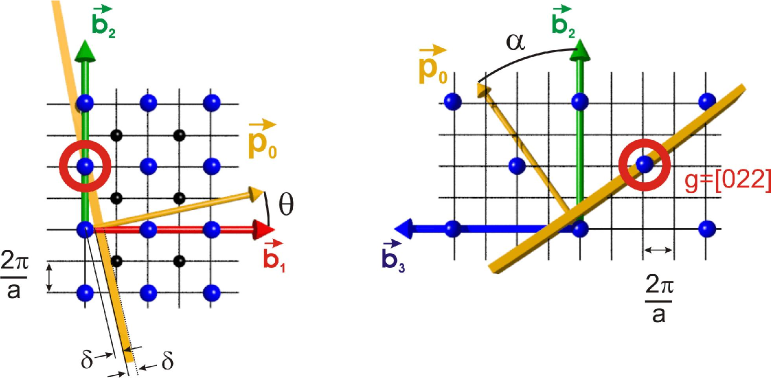
is composed of the Miller indices, , and the basis vectors of the reciprocal lattice, (below we use the nomenclature [h1h2h3]). Figure 1 shows the momentum vector in the reciprocal lattice space. For the selection of only one reciprocal lattice vector in the kinematical region of allowed recoils the angles in the plane and in the plane have to be carefully chosen. The pancake region is illustrated by the grey band perpendicular to the momentum vector .
Contributions to the coherent bs cross section only result from reciprocal lattice vectors within the pancake region. At a fixed orientation of the lattice, the pancake shifts with increasing photon energy, cf. eq. 4. Consequently, at a certain point a reciprocal lattice vector leaves the pancake. This leads to a discontinuity in the coherent bs intensity at the fractional photon energy
| (7) |
The plane of the electron deflection is fixed very tightly by the incoming electron momentum and the reciprocal lattice vector responsible for the coherent process. Hence, the linear polarisation of the emitted photons is oriented in the plane ().
3 Apparatus
The electron beam of ELSA Elsa06 hits the radiator target in front of
the tagging system KFP . Electron beams of = 2.4 GeV and
= 3.2 GeV were routinely used for experiments with linearly polarised photons.
The crystal has a front surface of (4 x 4) mm and thickness of m.
It is accurately positioned by a dedicated commercial 5-axis
goniometer111Newport Corporation, Irvine, CA 92606, USA.
The maximum angular uncertainty is rad due to the wobble
along the axes. Optical test measurements showed that other uncertainties,
like absolute accuracy, uni-directional repeatability and reversal value
(hysteresis) are negligible. The crystal, glued on a m kapton foil, is positioned in the common center
of the three rotation axes of the goniometer, horizontal (), vertical
() and azimuthal (), cf. fig. 2.
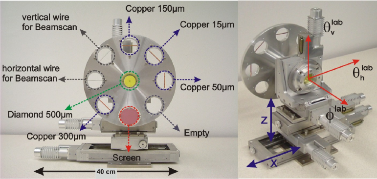
The minimum incremental motion (the smallest increment of motion the device is
capable of consistently and reliably delivering) of each rotation axes is
= 0.001 degree. Special measurements, discussed in sect.
4, confirm the orientation of the [100] crystal axis perpendicular to its front
surface.
Further copper radiators with different thicknesses and wires to scan
size and position of the electron beam are mounted
on a disk around the crystal, as can be seen in fig. 2.
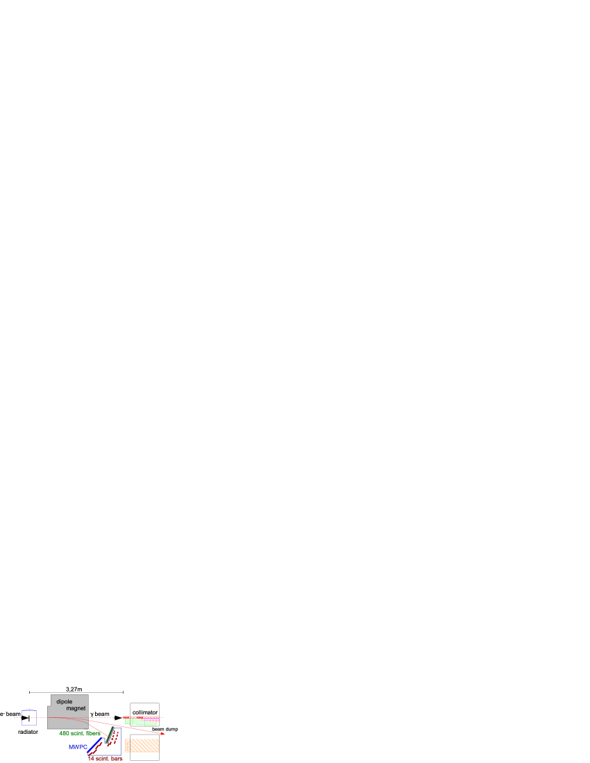
Electrons which radiated a photon are momentum analysed using the
tagging-spectrometer, as schematically depicted in fig. 3.
The detection system consists of 14 plastic scintillators providing fast
timing and additional hodoscopes, a 480 channel scintillating fibre detector and
a MWPC, to achieve a good energy resolution.
The optimisation and analysis of linear polarisation is solely
based on the data of the scintillating fibre detector which
covers the energy range .
The fibres are arranged in two layers. The individual fibres overlap by around
2/3 of their diameter. The energy resolution varies between 2 MeV for the high photon energies
and 25 MeV for the low energies for GeV.
The tagged photon beam remains virtually uncollimated.
Hence, the measured electron spectrum directly reflects the photon spectrum.
The orientation of the linear polarisation and the position of the coherent maximum in the photon energy-spectrum depends on the alignment of the crystal relative to the electron beam direction. Maximum polarisation is found in the plane (). The direction of the momentum vector in the reference frame of the crystal is defined by the polar angle, , and the azimuthal angle, , cf. fig. 1. The angle is the azimuth of the reciprocal lattice vector in the same reference frame. Given and , the position of the discontinuity, , in the energy-spectrum can be calculated Timm69 ; Lohmann94 :
| (8) | |||
Relations between crystal angles () and goniometer angles (, , ) for the g=[02] reciprocal lattice vector are given by Lohmann94
| (9) | |||||
| (10) | |||||
| (11) | |||||
| (12) | |||||
| (13) |
The angle defines the orientation of the polarisation plane, and are associated to vertical and horizontal linear polarisation, respectively. It is essential to determine all angular offsets between the crystal reference frame and the goniometer system on the one hand, and the incoming electron beam and the goniometer system on the other hand with sufficient accuracy. The former offsets have to be measured once in case of a fixed installation. The latter depend on the stability of the beam alignment and have to be determined repeatedly. For the alignment process we use the coherent bremsstrahlung itself as described in the next section.
4 Crystal alignment - Stonehenge Technique
The alignment is achieved by the Stonehenge Technique. The procedure can cope with a relatively large mounting misalignment and allows any arbitrary orientation of the polarisation plane to be selected. A detailed description is given in StoneKen ; StoneKen2 . The basis of the technique is a quasi azimuthal scan which sweeps the crystal axes in a cone of angular radius by stepping simultaneously on the horizontal and vertical axis of rotation:
| (14) | |||||
| (15) |
For each point of the scan a photon energy spectrum is measured and plotted in a polar diagram (Stonehenge plot), where the photon energy increases in the outward radial direction and the x- and y-directions correspond to the rotation axes and , respectively. In order to accentuate the coherence effect, the spectra are normalised to the spectrum of an amorphous copper radiator. Therefore the colour code of the diagram denotes the coherent intensity. A Stonehenge plot for a non aligned crystal taken for the Crystal-Barrel/TAPS experiment Elsner07 is shown in fig. 4.
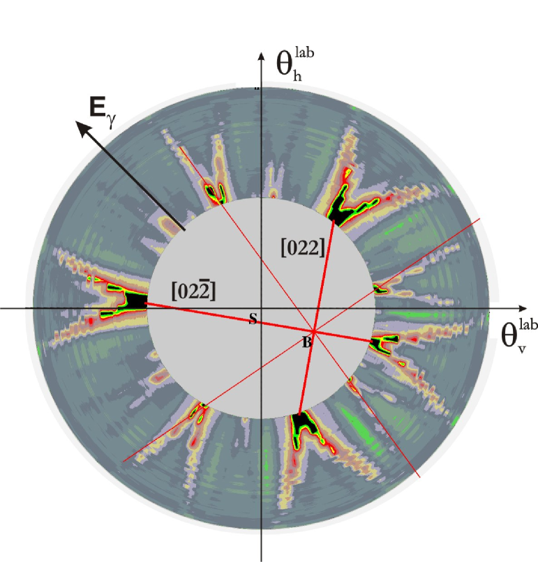
The coherent contributions from different settings of crystal planes result in
pronounced structures due to the different angles between crystal and electron beam.
The strongest intensities typically relate to the [022] and [02] reciprocal
lattice vectors and the points where they converge at E 0 (inner
circle) indicate where the corresponding setting of planes is parallel to the
electron beam. The analysis of the symmetry in the Stonehenge plots yields
all independent offsets of the crystal. For a detailed description of this
analysis method it is referred to StoneKen ; StoneKen2 .
Taking into account the angular offsets, it is
possible to set the linear polarisation at any desired spatial direction and
at any photon energy by choosing the crystal orientation.
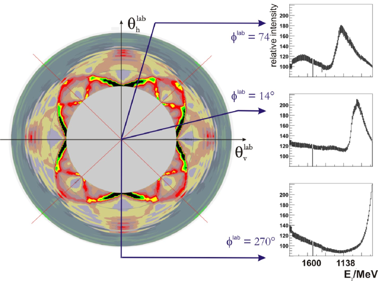
Figure 5 shows the Stonehenge plot of a perfectly aligned
crystal with a vertical orientation of the [022] plane. Three
one-dimensional sample histograms for different directions are shown on the right side.
The precision of the angular offsets depends on scan parameters, basically the
step size and the cone (cf. eq. 15). The resulting
azimuthal orientation has an accuracy of = 0.5 degree StoneKen2 .
In order to preserve the alignment during the experiment, the stability of the beam position
is monitored online, using the coherent peak itself, since the position of the
coherent peak in the energy spectrum is extremely sensitive to angle of the
incident beam.
As for the Stonehenge plots, also for beam diagnostics the
coherent spectrum is always normalised to the spectrum of an amorphous
copper radiator. At the beginning of each experiment a normalised reference
histogram is defined, which is compared with the online spectrum permanently.
The incoherent copper spectrum is measured in regular intervals.
5 Degree of linear polarisation
The generation of high degrees of linear polarisation
requires the isolated contribution of one of the [0,2,2,] reciprocal lattice
vectors to coherent bremsstrahlung.
Precisely determined offsets (cf. sect. 4) enable to deliberately set both,
the energy of the coherent peak and the orientation of the linear polarisation.
The determination of the polarisation degree is based on the comparison of the
measured electron spectrum with the ANB (“analytic bremsstrahlung
calculation”) software ANB from Tübingen University. The ANB code allows the calculation
of coherent intensities for each single reciprocal lattice vector. It integrates over all desired vectors.
Taking into account the incoherent contributions, the degree of polarisation
can be determined.
If there is no overlap of different reciprocal lattice vectors within a given
energy interval, the degree of polarisation can be obtained from any fit
of the intensity spectrum.
Figure 6 shows the ANB-calculated relative
photon intensity spectrum along with the calculated photon polarisation.
Due to a tiny overlap with the adjacent peak of the [04] vector the exact
determination of the polarisation degree from the experimental data alone is
not feasible. In our particular case no clear separation of the vector
[02] was realisable in the required energy region.
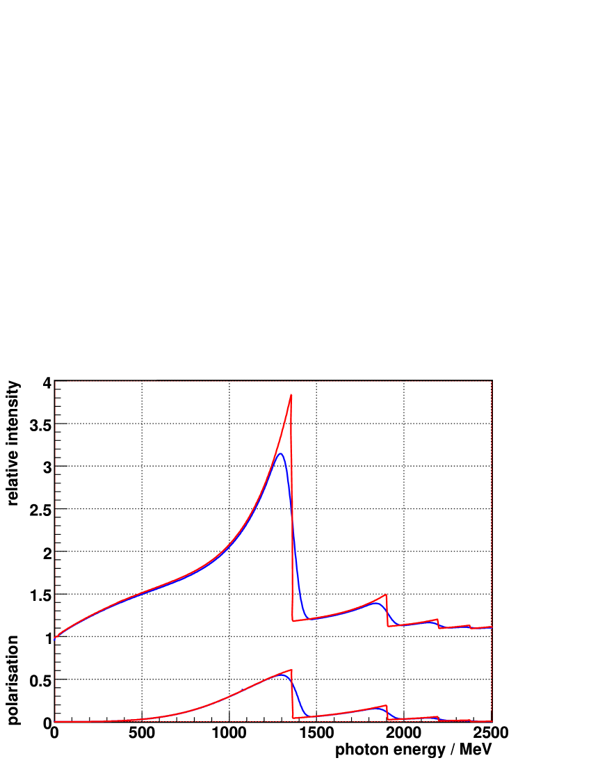
Under given experimental conditions the shape of the coherent spectrum is not determined by the crystal orientation alone. Each single process has a small deviation from the nominal kinematics as a result of beam divergence and multiple scattering in the crystal. Both effects cause a smearing of the sharp edge at the discontinuity position, due to the different pancake conditions for individual processes, and hence lower the intensity and consequently the maximum degree of polarisation (cf. fig. 6). The effects of beam divergence, beam spot-size, energy resolution and multiple scattering are included in the ANB software. Tables 5-5 show overviews of typical values for our experimental parameters. The electron-beam energy and the spot size are precisely measured. The values of the beam divergence result from calculations of the beam-line optic.
[h] electron energy 3176.1 MeV spot size 1.5 mm spot size 1.0 mm divergence 0.3 mrad divergence 0.08 mrad Electron beam properties.
[h] crystal thickness 0.5 mm calculated numbers of lattice vectors 1000 incoherent scaling factor 1.35 Radiator properties.
[h] Eγ(Pmax.)/MeV Pmax. /mrad /mrad 1305 0.49 -3.16 -56.78 1515 0.42 -4.09 -64.00 1610 0.39 -4.58 67.00 1814 0.31 -5.88 76.00 Coherent peak position, maximum degree of polarisation, , and crystal angles for the vertical orientation of the polarisation plane.
Additionally, collimation affects the degree
of polarisation, due to the different angular distribution for the coherent
and incoherent bs. However, no effective
collimation of the photon beam was used in the experimental.
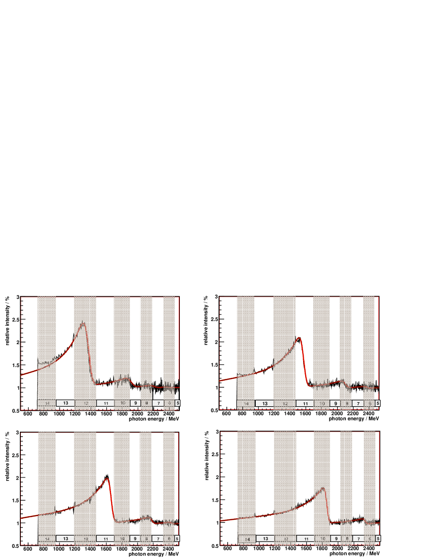
During the first round of CBELSA/TAPS data taking at ELSA four different crystal
settings were used, with maximum polarisation at =1305 MeV,
1515 MeV, 1610 MeV and 1814 MeV.
Vertical orientation of the polarisation vector was chosen, since
the vertical divergence of the ELSA electron beam is about an order of magnitude
smaller than in horizontal direction.
Normalised electron spectra are shown in fig. 7.
The curves represent a calculation using an improved version Elsner06 of
the original ANB software. The description of the measured intensity spectrum
is very accurate at all settings.
Two main improvements in the ANB code were
necessary to obtain this level of agreement between calculation and
experimental data.
The inclusion of multiple scattering was improved
by a more precise approximation of the angular distribution LD91 .
The original description H51 only accounts for the first order of the
series expansion of the scattering angle in Molière theory.
This accuracy was not sufficient to describe the experimental
spectrum. As a consequence a discrepancy appears in the steep edge of the coherent peak.
Furthermore, the incoherent description of the ANB software needs to be
scaled for all calculations by a factor of (cf. table 5).
This was traced back to an uncertainty in the parametrisation of the atomic
form factor.
A scaling of the atomic form factor according to Cromer and Waber CW65 by a
factor of yields the same result, as the scaling of the
incoherent part. Taking into account the form-factor parametrisation after Schiff
Sch51 , the difference of the form factors is also a factor of .
Consequently, the two alternative parametrisations provide an
uncertainty in the order of 10% in the required momentum-transfer region.
The relative strengths of coherent and incoherent contributions determine the
absolute value of linear polarisation. In this respect the
re-scaling of the incoherent contributions introduces no significant
additional error.
An absolute error of is estimated using variations of
the calculated relative intensity by . These worst-case estimate
accounts for deviations from the shape of the spectrum
due to combined statistical and systematical effects.
Assigning the appropriate photon energy to each single event in the
data analysis yields the event-weighted average polarisation in each bin of photon energy.
An independent cross check of the determination of the polarisation degree
is the measurement of the photon beam-asymmetry, ,
in an energy region were it is well known from other independent measurements.
This is discussed in the next section.
6 Beam asymmetry in photoproduction
The analysis of the photon beam-asymmetry, , in the reaction provides a well suited consistency check for the determination of the degree of polarisation. Large photon asymmetries are involved, especially at small angles , and a zero-crossing at certain energies. Comparing our results to earlier measurements at GRAAL222GRenoble Anneau Accelerateur Laser GraalPi gives an independent check, in particular because at GRAAL linearly polarised photon beams are produced by a different process, laser backscattering, with a well defined and high degree of polarisation. Our results are based on the same data set and data analysis presented in a previous publication on the beam asymmetry in photoproduction Elsner07 . The experimental setup and the main steps of the data analysis are shortly summarised in the following.
6.1 Experimental setup and data analysis
The linearly polarised photon beam from the tagging system
(cf. Sec. 3) was incident on a cm long liquid hydrogen
target. The target is surrounded by a cylindrical, three layer scintillating fibre
detector, covering the polar angular range from 15 to 168 degrees,
and the Crystal Barrel (CB) detector CBarrel , consisting of 1290
individual CsI(Tl) crystals covering a polar angular range of 30
— 168 degrees.
The forward cone of — 30 degree was covered by the
TAPS detector, a setup of 528 BaF2 modules at a
distance of cm from the target.
Charged particle recognition is obtained by the hit information from the
plastic-scintillator modules in front of TAPS and the scintillating
fibre detector inside CB. The first level trigger was derived from the
TAPS detector modules, which are individually equipped with photomultiplier readout.
Two alternative trigger conditions were used, either hits above a low threshold () or
hit above a high threshold ().
Within s, a fast cluster recognition for the Crystal Barrel
provides the second level trigger ().
Finally, the total trigger condition required 2 clusters identified: .
The offline analysis is based on three detector hits, corresponding to two
photons from the pion decay, and the proton. A photon hit is usually
composed of a cluster of adjacent crystals whose energy is summed over.
Due to the detection of the proton, the kinematics is overdetermined.
The analysis starts with all combinatorial possibilities, i.e. 3 for the 3–cluster events.
No charged particle identification for the proton was used to avoid false
azimuthal distributions due to inefficiencies of the veto detectors.
Furthermore, only the angular information of the proton candidate was used.
The energy of the proton candidate was disregarded.
Kinematic cuts, based on longitudinal and transverse momentum conservation,
are used to extract the desired reaction.
Additionally, a cut on the missing mass was applied to the proton candidates
(m 150MeV).
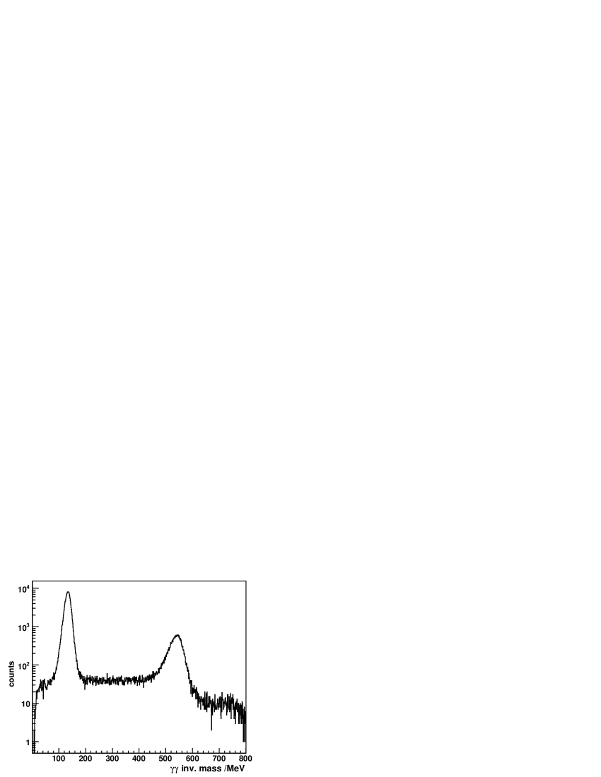
Figure 8 shows the two-photon invariant mass distribution
Elsner07 obtained. Below the and peaks the overall
background is very small (note the logarithmic scale).
After background subtraction a clean event sample was obtained from cuts of width around the mass
in the invariant mass spectra.
The cross section of pseudoscalar meson photoproduction
off a nucleon with linearly polarised beam DKT99 is given by
| (16) |
the beam asymmetry, , can be extracted from the modulation of the cross section over the azimuth. In eq. 16 denotes the polarisation independent differential cross section, the degree of linear polarisation of the incident photon beam, and the azimuthal orientation of the reaction plane with respect to the plane of linear polarisation. From a fit of the azimuthal event distribution
| (17) |
the product of beam asymmetry and photon polarisation, , is given by the ratio in each bin of photon energy and pion angle, . Finally, the event-weighted average polarisation, assigned as described in Sec. 5, allows the determination of in each data bin.
6.2 Results
Figure 9 shows the results for the beam asymmetry extracted for one crystal setting with a maximum degree of polarisation at Eγ = 1305 MeV. Statistical errors are directly attached to the data points. The bars indicate the estimated total systematic uncertainty. The major contribution to the systematic error of this experiment stems from angle-dependent inefficiencies Elsner06 . Data within the range = 60 – 100 degree are missing due to the trigger condition , which was used to select events with higher photon multiplicity than . In fig. 9 our data are compared to data of the GRAAL collaboration GraalPi .
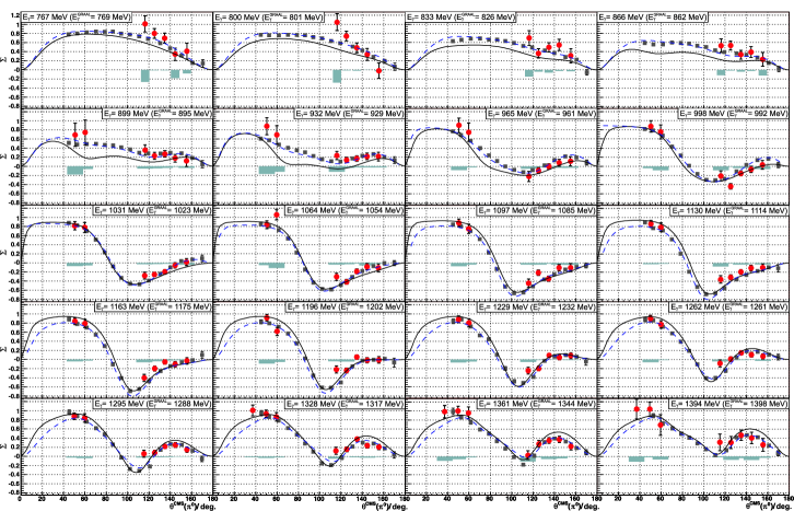
Both data sets show a very good agreement, despite
small fluctuations around = 115 degree.
The kinematics of these data points are correlated to a very low proton energy,
probably the protons got stuck in the -unsymmetrical holding structure of the inner
detector. This -dependence of detection efficiency affects directly the experimental asymmetry.
Figure 9 also shows the good agreement between both
data sets and two standard calculations, the Mainz isobar model MAID CYTD02
and the Bonn–Gatchina partial wave analysis BnGa Anisovich05 .
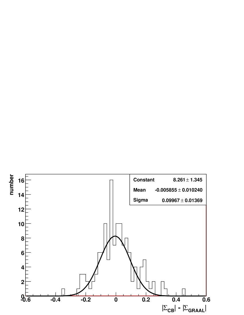
An explicit deviation of both data sets is shown in fig. 10.
The difference of the absolute values of the beam asymmetries () is plotted in one histogram. This representation is more
sensitive to an incorrect measurement of the photon polarisation than the
difference of the signed values.
In fig. 10 the mean value of a gauss distribution
is compatible with zero. Also the width (sigma) corresponds to
our mean statistical error. Consequently this cross check shows no indications for an
additional contribution to the systematic error in the determination of the
degree of polarisation. Hence we conclude that the absolute determination of
the degree of linear polarisation is under control on the level of the
estimated errors given in sect. 5.
7 Summary
We have presented the method to produce a linearly polarised photon
beam at ELSA by means of coherent brems-strahlung off a diamond crystal.
Within the photon energy range MeV we achieve
polarisation degrees up to 49 %. At higher energies the polarisation reduces
to e.g. Pγ 30% at Eγ = 1800 MeV.
The precise orientation of the diamond crystal versus the incoming
electron beam is essential. It is realised by a 5-axis goniometer. The
alignment is based on the Stonehenge Technique.
Both, the relative intensity spectrum and the polarisation degree,
have been calculated with an improved version of the ANB software.
An independent consistency check is provided by the measurement of the photon
beam asymmetry, , in the reaction .
The combined setup of the Crystal Barrel
and TAPS detectors enabled a high-resolution detection
of multiple photons, important for the clean detection of the
decays of the pion.
The obtained photon asymmetries are compared with a previous
measurement by the GRAAL collaboration.
A very good overall consistency of the data sets is obtained.
No deviations were visible beyond the error of given
above. The production of linearly polarised photons via coherent bremsstrahlung and
the presented method of determination of the degree of polarisation is now
routinely used as a standard technique at ELSA.
Acknowledgements.
We are happy to acknowledge the continuous efforts of the accelerator crew and operators to provide stable beam conditions. K. Livingston from Glasgow university deserves a big share of credit for his invaluable help in setting up the Stonehenge technique for the crystal alignment. This work was financially supported by the federal state of North Rhine-Westphalia and the Deutsche Forschungsgemeinschaft within the SFB/TR-16. The Basel group acknowledges support from the Schweizerischer Nationalfonds, the KVI group from the Stichting voor Fundamenteel Onderzoek der Materie (FOM) and the Nederlandse Organisatie voor Wetenschappelijk Onderzoek (NWO).References
- (1) G. Knöchlein, D. Drechsel and L. Tiator, Z. Phys. A352, 327 (1995).
- (2) D. Elsner et al., Eur. Phys. J. A33, 147 (2007).
- (3) W.-T. Chiang and F. Tabakin, Phys. Rev. C55, 2054 (1997).
- (4) T. Nakano et al., Nucl. Phys. A684, 71c (2001).
- (5) O. Bartalini et al., Eur. Phys. J. A26, 399 (2005).
- (6) D. Lohmann et al., Nucl. Instr. and Meth. A343, 494 (1994).
- (7) P.L. Cole et al., proceedings GDH 2002 Genova, World Scientific Publishing Co. Pte. Ltd.
- (8) W. Hillert, Eur. Phys. J. A28, 139 (2006).
- (9) F.H. Dyson and H. Überall, Phys. Rev. 99, 604 (1955).
- (10) H. Überall, Phys. Rev. 103, 1055 (1956).
- (11) H. Überall, Phys. Rev. 107, 223 (1957).
- (12) H. Überall, Z. Naturforsch. 17a, 332 (1962).
- (13) G. Diambrini Palazzi, Rev. Mod. Phys. 40, 611 (1968).
- (14) U. Timm, Fortschritte der Physik 17, 765 (1969).
- (15) K. Fornet-Ponse, Eur. Phys. J. A, The photon tagging system of the CB-experiment at ELSA, in preparation (2008).
- (16) K. Livingston, International Conference on Charged and Neutral Particles Channeling Phenomena, Proc. SPIE, (2005).
- (17) K. Livingston, Nucl. Instr. and Meth. The Stonehenge Technique. A new method of aligning crystals for linearly polarized photon production from coherent bremsstrahlung, in preparation (2008).
- (18) D.T. Cromer and J.T. Waber, Acta. Cryst. 18, 104 (1965).
- (19) F.A. Natter et al., Nucl. Instr. Meth. B211, 465 (2003).
- (20) L.I. Schiff, Phys. Rev. 83, 252 (1951).
- (21) J.H. Hubbell, J. Appl. Phys. 30, 981 (1959).
-
(22)
D. Elsner, doctoral thesis, Bonn (2006) http://hss.ulb.uni-bonn.de/diss_online/math_nat_fak/
2007/elsner_daniel/index.htm. - (23) G.R. Lynch and O.L. Dahl, Nucl. Instr. Meth. B58, 6 (1991).
- (24) A.O. Hanson et al., Phys. Rev. 84, 634 (1951).
- (25) E. Aker et al., Nucl. Instr. Meth. A321, 69 (1992).
- (26) R. Novotny et al., IEEE transaction on nuclear science 38, 378 (1991).
- (27) D. Drechsel, S.S. Kamalov and L. Tiator, Nucl. Phys. A645, 145 (1999).
- (28) W.T. Chiang, S.N. Yang, L. Tiator, D. Drechsel, Nucl. Phys. A A700, 429 (2002).
- (29) A.V. Anisovich et al., Eur. Phys. J. A25, 427 (2005).