Why the two-pulse photon echo is not a good quantum memory protocol
Abstract
We consider in this paper a two-pulse photon echo sequence as a potential quantum light storage protocol. It is widely believed that a two-pulse scheme should lead to very low efficiency and is then not relevant for this specific application. We show experimentally by using a Tm3+:YAG crystal that such a protocol is on contrary very efficient and even too efficient to be considered as a good quantum storage protocol. Our experimental work allows us to point out on one side the real limitations of this scheme and on the other side its benefits which can be a source of inspiration to conceive more promising procedures with rare-earth ion doped crystals.
pacs:
03.67.-a, 32.80.Qk, 42.50.Md, 42.50. p, 42.50.Gy, 42.50.MdI Introduction
The prospect of quantum light storage in solids motivates us to reconsider the interaction of light and matter at the single quantum level. Historically coherent transient phenomena appeared very active because they are primarily based on two-level system absorption. The community naturally focused on rare-earth ion doped crystals (REIC) instead of atomic vapors because the storage time can be long as well and is not limited by the atomic diffusion whatsoever. Recent proposals are of course inspired by previous realizations of classical light memories mossbergOL83 and all-optical processing more generally babbitAO94 . In this lineage recent progresses toward quantum storage are involving common physical ingredients. Because of the large inhomogeneous broadening, any light retrieval is intimately related to a dipole rephasing. Surprisingly the very well known conventional photon echo has not been considered as a promising quantum protocol despite impressive realizations in the classical domain. A major identified drawback is the low efficiency of the process moiseevPRL01 ; moiseevJOB03 . This has been a commonly admitted idea since the pioneering studies of the 60’s hartmann64 . Although we roughly adhere to this statement, we would like to point out that high retrieval efficiency was already observed in a specific regime of two-pulse photon echo (2PE) cornishPRA98 ; cornishOL00 , which might pave the way to quantum light storage. Our experimental work consists of a clear observation of the large predicted efficiency in this regime we first need to precisely defined. Our analysis is also stressing clearly what are the physical ingredients which lead to this result. Our study is definitely placed in the prospect of a quantum memory. With respect to other protocols, we finally clarify the advantages and drawbacks of this technique that should be considered as a general tool for coherent manipulations.
As mentioned before, the investigation of classical light storage largely paved the way toward their quantum equivalent. REIC have shown interesting processing capabilities especially with all-optical control babbitAO94 ; tian . As derived from the conventional photon echo, these techniques are based on an optical manipulation of the coherences. Experiments largely benefit from the agility of the laser controlling the crystalline processor crozatier . This convenience would be still appreciable for manipulation at the quantum level. The 2PE time-to-bandwidth product properties should also be emphasized. In the 2PE process, this parameter, critical for information processing applications, is not limited by the memory opacity, in contrast with the most promising quantum storage protocols involving REIC, namely the ”stopped-light” approach EITlukin ; turukhin2002 or the ”controlled reversible inhomogeneous broadening” (CRIB) procedure crib1 ; alexander2006 ; crib3 ; hetet07 . Finally, contrary to the above storage protocols, doesn’t require any initial state preparation. A spectral selection within the inhomogeneous broadening is in a sense build-in because of the selective excitation of the first incoming pulse that we define as the signal. The 2PE has the singular advantage to rephase a random distribution of level shifts without any assumption on the source of inhomogeneity. By clarifying the characteristics of the 2PE, we aspire to a deeper understanding of the atomic coherences optical manipulation.
Since the observation hartmann64 and the interpretation hartmann66 of the photon echo, the quantitative comparison with the observed efficiency has been widely studied. At the basis of data processing application, the interest has been renewed relatively recently cornishPRA98 ; mossbergPRA99 . A realistic approach of the problem usually requires a numerical resolution of the Bloch-Maxwell equations mossbergOC98 . This gives a solid interpretation of the experimental data mossbergPRA99 . As a matter of fact investigating the 2PE for quantum light storage is strongly simplifying the problem. As compared to the canonical 2PE where a excitation pulse is followed by a rephasing pulse, memory-like version of this scheme would first involve a very weak signal pulse. In that very specific case as pointed out by Tsang et al. cornishJosab03 , one can derive an analytic solution for the efficiency. In this paper, we will first deduce these equations from a simple physical interpretation of the scheme. We will clearly specify the underlying assumptions to be verified in practice. We will then compare these calculations to the experiment. A detailed analysis of our observations allows us to conclude and place this work in the context of a quantum memory by comparison to other storage protocols.
II Efficiency of the protocol
This subject has been covered by a wide range of literature cornishPRA98 ; cornishOL00 ; cornishJosab03 ; mossbergPRA99 ; mossbergOC98 . Nevertheless it is relatively easy to derive these equations based on simple physical arguments. The interaction of light pulses with our medium is well described by the Maxwell-Bloch equations assuming the slowly varying amplitude and the rotating wave approximations.
| (1) |
where is the detuning, is the Rabi frequency of the field under consideration and the three components of the Bloch vector. The decay of the coherences and the population is assumed to be negligible. We have dropped the usual term because realistically the spatial extension of the pulse is always much longer the length of our crystal.
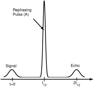
To describe the broadest range of situation a numerical resolution of the system is usually necessary mossbergOC98 . This is not our approach. A sketch of the time sequence is depicted in Fig.1 and looks like any 2PE sequence. Nevertheless within the prospect of quantum storage, the signal and the echo are assumed to be weak. This greatly simplifies the description crisp essentially because these two fields do not modify the population difference that is not time dependent anymore. This is the small area approximation where the Maxwell-Bloch system can be linearized crisp .
II.1 Calculation in the weak signal limit
If the three pulses are well separated in time, one can consider them independently. The signal, the rephasing pulse and the echo are respectively centered on , and . The incoming signal and outgoing echo Rabi frequencies are respectively denoted and . The propagation of is simply described by an absorption law if the atoms are initially in the ground state crisp :
| (2) |
The weak echo is expected to behave in a similar way, except the medium has been previously excited and modified by the signal and the rehasing pulse. Therefore the echo equation reads as:
| (3) |
The coherence , resulting from interaction with the first two pulses, evolves freely within the time interval . The population has been affected by the rephasing pulse. We assume the rephasing pulse is much shorter than . Therefore the population is uniformly modified by the rephasing pulse all over the spectral interval initially excited by . We will see in III how this constraint is treated experimentally. A second benefit of this assumption is that the rephasing pulse can be consider as instantaneous (time ) and then uniformly modifying the coherences. The physical interpretation of Eq.3 is based on the generation of by the macroscopic dipole that builds up when the coherences get phased together. The growing field propagates through the medium characterized by the uniform population difference .
We aim at reducing Eq.3 by expressing the atomic quantities in terms of the optical fields only. We shall be left with an equation of propagation for . The echo efficiency will be deduced from the solution of this equation. We first have to track the excitation of the coherences by the signal, then their modification by the rephasing pulse and finally their free evolution toward the echo emission. The problem is addressed locally, at position . The signal excites the atoms that initially all sit in the ground state:
| (4) |
At a certain time between and the signal field is off. We then recognize the Fourier transform of written , the accounts for the free evolution during this interval.
| (5) |
This expression represents the evolution of the coherence after the initial absorption process and before the rephasing pulse. Next, we calculate this strong pulse effect on the coherences (how is related to ) and on the population, which modifies the echo propagation (Eq.3). This can be done analytically by integrating the Bloch-Maxwell equations (see ref. cornishJosab03 ). Nevertheless the results are relatively intuitive at the end and can be derived from simple physical ingredients. This can be done first of all in the specific case of a -rephasing pulse, the more general case of an area for the strong pulse can be solved by introducing ”by hand” geometrical factors. All over the spectral interval excited by the signal pulse, the rephasing pulse is assumed to behave as a -pulse. This corresponds to a brief pulse assumption. The experimental fulfillment of this condition will be addressed in III. A -pulse simply drives the Bloch vector by a rotation of around an equatorial axis. On the one hand, along the population axis it corresponds to an inversion from to at the time . On the other hand, it transforms the coherences , stays the same (complex conjugation of ). Right after the rephasing pulse, Eq. 5 becomes
| (6) |
where the complex conjugation sign accounts for the rephasing transformation. The coherences are freely evolving after . One can now write the propagation equation of the echo (Eq.3) by including the direct influence of the signal on . The signal field being assumed to be a real number, one recognizes the time-reversed signal whose dependency is given by an absorption law (Eq.2)
| (7) |
The signal field acts as a source and generates the echo that propagates in an inverted medium. This gives the equation of propagation for a -rephasing pulse. It is now rather easy to account for an imperfect rephasing. More generally, a -area strong pulse drives an -rotation of the Bloch vector. The population is not fully inverted anymore: . The rotation of the coherences is also incomplete and limited to of its maximum value. This factors are purely geometrical and are interpreted as projections on the Bloch sphere. We finally get the general analytic expression for the efficiency. This expression has been previously derived by Tsang et al. (cornishJosab03, , Eq.(40)) by integrating the Bloch-Maxwell equations. Here we simply focus on the two crucial stages, the absorption of the signal on one side and the re-emission of the echo on the other side. The rephasing pulse in between is interpreted as an instantaneous manipulation of the Bloch vector.
| (8) |
There is an underlying assumption here: the rephasing pulse is very brief and is then fully covering the spectral range of excitation. As a consequence the echo is not deformed as compared to the signal, it is only time reversed. The -rotation on the Bloch sphere is also uniform and doesn’t depend on . The -dependency of the area accounts for the propagation of the strong pulse itself. This is usually a complicated problem but in that case we are only interested in the propagation of the area. The result is remarkably simple and is given by the Area Theorem of McCall & Hahn mccall1967 . We don’t have to know the exact temporal shape through the propagation because the area is the relevant quantity for the rephasing pulse and is simply given by
| (9) |
It can be solve analytically for a given . A straightforward integration of Eq.8 allows us to calculate the retrieval efficiency as a function of the optical thickness where is the length of the medium:
| (10) |
For different optical thickness , we plot the efficiency as a function of the rephasing pulse area in Fig.2.
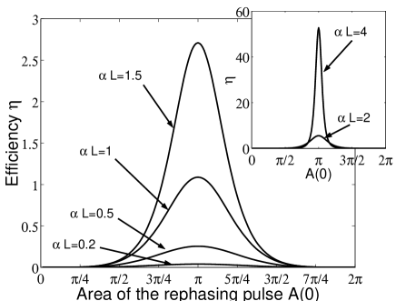
We observe in that case that the efficiency is strongly depending on the optical thickness. When it is low, the efficiency is weak essentially because the signal is poorly absorbed. The efficiency is then a sinus-like function and the rephasing area directly accounts for an imperfect rotation on the Bloch sphere. On the other side, at large optical thickness, the efficiency can be much larger than unity but only on a narrow window around a . This specific situation is certainly the most interesting because the signal in fully mapped into the medium (large optical thickness) and the efficiency is exceptionally large. The -rephasing pulse have very particular properties that can be interpreted independently to physically understand this behavior.
II.2 Specificity of the -rephasing pulse
The case of an exact -rephasing pulse is relatively straightforward. More fundamentally it allows us to understand the expected efficiency at large optical thickness. We simply derived the propagation equation (7) for the echo by assuming that locally, at position , the area is exactly . Now we have to examine the -pulse propagation inside the medium. This is a very specific situation. According to Eq.9 a -pulse preserves its initial area throughout the medium. Even if the energy is absorbed, the area is conserved as the pulse stretches temporally ruggiero . Roughly speaking, if the pulse is elongated by a factor , the amplitude (Rabi frequency) is reduced by to conserve the area and the energy decreases by a factor . This alteration is a pure coherent propagation effect.
The propagation equation 7 is then valid at any position and easily gives the efficiency. This expression is consistent with our general formula Eq. 10:
| (11) |
At large optical thickness, the efficiency is much larger than unity and grows exponentially. This is relatively counter-intuitive. The echo efficiency is generally observed to be low, which is usually assigned to absorption. As mentioned before the -rephasing pulse retains its area along the propagation. In other word, the medium is completely inverted: the echo is emitted in an amplifying medium. This explains why the echo is gaining exponentially. Practically, the assumptions we made, such as 1-dimension, infinite plane wave geometry, will be difficult to satisfy. Any divergence from the ideal theoretical frame shall affect the echo efficiency.
The -pulse propagation is not only unusual, it is also a singular solution of the Area Theorem. The -solution is indeed not stable because any area slightly lower (or larger) than will decrease (or increase resp.) toward (or resp.) mccall1967 ; ruggiero . Even so, the pulses with an area close to can propagate deeper inside the medium than a weak pulse. To see that we plot in Fig. 3 the penetration depth at which the incoming area is divided by (the curve is symmetrized around to account for the deviation toward of pulses larger than ).
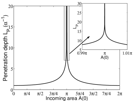
For small areas, this length is as expected crisp . As one gets closer to , the pulse can propagate deeper inside the medium. For example, if the incoming area is controlled at the 1% level (inset Fig. 3), the penetration depth is larger than . The curve is very narrow about which shows a high sensitivity for the propagation. Realistically a well-controlled -pulse should induce a population inversion much deeper inside the medium than the absorption length . If this depth is larger than the optical thickness of the medium, it will be fully inverted. However, the deeper the -pulse propagates through the absorbing medium, the more it is stretched, since it has to keep a constant area while losing energy. The pulse bandwidth shrinks accordingly, making the pulse act as a -pulse on a reduced spectral interval ruggiero .
Based on this analysis, we expect to observe two remarkable qualitative features. The efficiency should be very high at large optical thickness and strongly depending on the area of the rephasing pulse.
III Experiments
A 2PE experiment can be performed in any system were a transient phenomena can be observed. Here we use a thulium-doped yttrium aluminum garnet (YAG), cooled down to cryogenic temperature. The long optical coherence time makes it particularly attractive for quantum storage application. We will now briefly describe the experimental set-up and focus on the precautions we take to satisfy the assumptions introduced previously.
III.1 Experimental set-up
Our 0.5% Tm3+:YAG crystal is immersed in liquid helium at 1.4K. The coherence time of the 3H6(0) to 3H4(0) transition is typically in these conditions. The crystal is oriented and cut in order to propagate along the [10] direction. Along this axis, the length is 5mm and the optical thickness . The laser polarisation is parallel to [111] to maximize the Rabi frequency ConeNutAngle . The laser system is operating at 793 nm, stabilized on a high-finesse Fabry-Perot cavity with the Pound-Drever-Hall technique (200Hz over 10ms) crozatier2004 . The laser is split in two independent beams. Temporal shaping is achieved by two acousto-optic modulators (AOM) controlled by a dual channel arbitrary waveform generator (Tektronix AWG520). Both beams are injected into two single mode fibers. Before recombination on a beamsplitter, we use expanders to independently manage their waists inside the crystal. After the sample, the signal is collected in a single mode fiber terminated by a photodiode.
The signal is supposed to mimic a weak quantum field, so this pulse should verify the small area approximation. The signal beam is in practice much weaker than the rephasing one. At the maximum, there is a 36dB power difference between the two. More precisely, the signal area is kept constant at 9% of and we vary the rephasing pulse area from 0 to .
Keeping the rephasing pulse significantly briefer than the signal pulse is the most stringent condition we have to satisfy. This is required to maintain a uniform coverage of the rephasing process over the signal excitation bandwidth. To do so, we use gaussian-shaped signal (duration ) and rephasing pulses. On the one hand a gaussian pulse is spectrally narrower than a rectangular pulse with the same duration. On the other hand we observed a gaussian -pulse undergoes less temporal streching than a gaussian one after propagation through an absorbing medium. We set the rephasing pulse times shorter than the signal. This value is slightly fluctuating depending on the rephasing amplitude value. Changing the AOM driving power marginally impacts on the pulse shape. A much shorter pulse would be preferable but we are limited by the available power (few milliwatts) to ensure a significant area in a reasonable time.
One last point we ignored so far is the transverse dimension of the beams. To be consistent with the 1-dimension theory, the power of the rephasing beam should be constant over the spatial extension of the signal. The signal beam waist () is then chosen to be 2 times smaller than the waist of the rephasing beam (). This is the same overlap argument we used in the spectral domain.
III.2 Results
We perform a 2PE experiment in the beforementioned conditions (see Fig. 4). We pay special attention to an accurate calibration of the rephasing pulse area. We indeed first perform an optical nutation experiment to evaluate the exact Rabi frequency of the pulse. Comparing the signal and rephasing beam intensities, we estimate the area of the signal which is confirmed to be weak ().
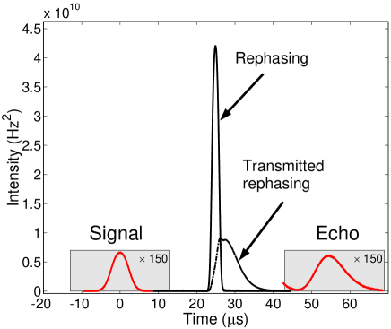
As expected, we observe an echo at delay after the rephasing pulse (see Fig. 4 ). We also carefully calibrate the efficiency. To do so, we shift the laser far from the absorption line (a few cm-1). The corresponding intensity level represents the 100% reference line on the measurement detector. According to the efficiency definition given by Eq. 10, the echo is assumed to exhibit the time-reversed temporal shape of the signal. This is not exactly the case experimentally as we shall discuss later. So we define the efficiency by comparing the maxima of the two pulses:
| (12) |
By varying the incoming rephasing area, we obtain as a function of (see Fig. 5).
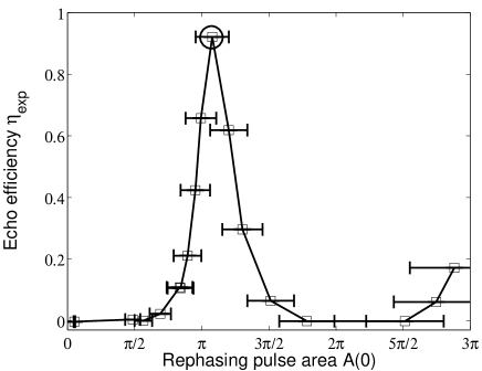
The main source of uncertainty is due to the alignement and the spatial overlap of the beams in the crystal. To quantify it and derive error bars, we estimate the typical intensity variation of the rephasing beam (waist ) over a length corresponding to the signal waist (). This is simply given by the direct comparison of two gaussian curves (11% in that case, which gives the horizontal error bars in Fig. 5).
III.3 Discussion
The experimental results are qualitatively in good agreement with the expected efficiencies in Fig. 2. The main features are indeed observed. First of all the maximum efficiency is obtained for a -area, which is consistent with , within the error bar. We also observe a reincrease of the efficiency close to after a minimum at . We certainly predict a maximum at any odd number of , but we are experimentally limited by the available laser power. Secondly, the curve is peaked in the vicinity of and cannot be fitted by a sinus-shape oscillation. This is also expected (see Fig. 2) and is due to the large optical thickness of the sample . Finally, the maximum efficiency is relatively high 0.92 for (circle in Fig. 4). Although far below the predicted value (Eq. 11), this result demonstrates a highly efficient 2PE.
We can invoke many reasons to explain the discrepancy between the measured and the predicted efficiency values. (i) The first obvious one is the total duration of the time sequence. The echo is indeed decaying exponentially because of the coherence lifetime which has been completely neglected in our treatment. In our case so the echo is reduced by a factor . Without this decay, the efficiency would be much larger than unity. In section IV we shall see why is chosen to be long for this experiment. (ii) Another limitation is certainly due to the duration of the rephasing pulse. With this pulse 2.5 times shorter than the signal, the incoming pulse spectral overlap is rather good. However, propagation through the sample strongly stretches the rephasing pulse, as expected from discussion in Sec. II.2, and as observed in Fig. 4. The pulse cannot be considered as much briefer than the incoming signal all the way through the sample. An observable proof of this effect is the retrieval time of the echo (Fig. 4). The retrieval should be centered on . We clearly see that the echo is delayed by few microseconds. Indeed, because of stretching the rephasing pulse is no longer centered at a delay from the signal. The retrieval time is shifted accordingly. Since one of the assumption of our model is not fully verified, we then expect an efficiency reduction. (iii) In the spatial domain, the same argument is also valid. The signal is tightly focused ( to ensure that its waist is smaller that the rephasing beam. The associated confocal parameter is typically two time shorter than the crystal length. So the rephasing beam does not overlap the signal uniformly all along the propagation. In other words, the rephasing area is not constant in the transverse direction. This should reduce the efficiency and broaden the peak around (convolution effect).
Based on this analysis, we believe our model contains all the physical ingredients to explain qualitatively the experimental results. We have given three probable explanations to interpret the quantitative discrepancy with the predicted values.
IV Relevance for quantum memory application
Our experiment has been performed in the classical domain using weak small-area pulses. It tells us however what should be the limitations in the quantum domain.
An obvious one is already present in our experiment. Since the rephasing pulse stretches while propagating through the sample, it gains a trailing tail that is not negligible as compared to the echo amplitude. As we can see in Fig. 4 at the pulse tail is falling slightly before the echo comes out. That’s the reason why we cannot make shorter, otherwise the echo would be submerged. With only few photons in the signal, this effect would be disastrous. As already discussed, the strong pulse distortion is not an artefact. This is a coherent propagation effect ruggiero , thus a fundamental limitation. This should not be confused with the noise induced by the fluorescence, which will be another limitation at the few photons level.
The rephasing process is inherently associated with a population inversion. The decay has been neglected in our model. In practice the medium excitation will be followed by spontaneous emission. The fidelity of the 2PE as a quantum memory protocol is fundamentally limited by fluorescence. This can already be understood within the framework of the Dicke model dicke , i.e. without taking propagation effects into account. Consider an ensemble of two-level systems, where the two states are denoted and for the -th system. Note that we are interested in the case where the transition energy for the to transition is slightly different for different systems (inhomogeneous broadening).
We will compare the case where the input to be stored is a single photon to the case where there is no input (i.e. where the input state is the vacuum). The initial state of the atomic ensemble is . For a vacuum input, this state remains of course unchanged. It is then transformed to by the -pulse. For a single photon input, absorption of the photon creates a state of the form
| (13) |
which contains a single atomic excitation. (Propagation effects would lead to the coefficients of the terms not being all the same.) The -pulse transforms this state into
| (14) |
which has atomic excitations.
In an inhomogeneously broadened system, the various terms in Eqs. (13,14) will acquire different phases depending on the transition energies of the various atoms. However, at the time of the echo all terms will be in phase. Emission from the state gives rise to the echo signal corresponding to a single-photon input, whereas emission from the state corresponds to a vacuum input and thus defines the noise background due to fluorescence. The photon emission probability for a state is proportional to , where . This is due to the fact that the interaction Hamiltonian between the atomic ensemble and the relevant mode of the electro-magnetic field (corresponding to emission in the direction of phase matching) is proportional to .
Following Ref. dicke it is easy to see that and . As a consequence, the probability to emit a photon at the echo time is only twice as large for a single-photon input as for no input at all, corresponding to a signal-to-noise ratio of one. This severely limits the achievable fidelity of quantum state storage.
Finally, from what we have shown is this article, we can conclude that the efficiency is actually too high for quantum memory application. We indeed observed a maximum 92% retrieval but the efficiency can be much larger than unity with optimized conditions cornishOL00 . This amplification due to the medium inversion is precisely a propagation effect that is not considered in the beforementioned Dicke model. This is a key ingredient to interpret our experimental results. In quantum optics terms, the statistics of the field will be modified: for one photon coming in, more than one will come out. Because the medium is inverted, it actes as a gain medium and modifies the quantum field and then again reduces the fidelity GainMed . In that sense, the 2PE is also too efficient to be a good quantum protocol.
Those reasons are three fundamental limitations that we expect in the quantum regime. Even if the 2PE suffers from drastic drawbacks, it should be considered with attention. It is not only a historical example that helps us to understand rephasing phenomena. It has the unique ability to rephase atoms with randomly distributed level shifts, whatever the distribution structure crib3 . This a major difference as compared to CRIB (Controlled Reversible Inhomogeneous Broadening) crib1 ; hetet07 ; crib3 ; alexander2006 where the first initial step is a spectral tailoring of the distribution. There is not preparation of the system in the 2PE. The feat performed by the CRIB protocol is its capability to produce a rephasing of the coherence without any population inversion. As a consequence the equations of the 2PE (Eq. 7) and the CRIB sangouard are remarkably similar except that a minus sign accounts for the population inversion in the propagation equation. One can finally wonder if an optical manipulation would achieve a rephasing in the ground state as the CRIB does. This is a priori not possible because even a complex optical sequence will be decomposed with rotations on the Bloch sphere, on contrary the CRIB protocol can be interpreted as a planar symmetry (detuning sign reversal). These two are then intrinsically and fundamentally different.
We have here listed the limitations of the 2PE when considered as a potential quantum storage protocol. We pointed out the pulse deformation than can be a technical issue when using strong pulse. The two other limitations are directly and fundamentally related to the medium inversion induced by the optical rephasing operation. On one side the spontaneous emission will produce a noise comparable to the retrieved signal and then deteriorate the storage fidelity. On the other side the inversion will make the medium amplifying, which mainly explains the large predicted and observed efficiency. A larger than one efficiency is also associated with a fidelity reduction for quantum fields.
V Conclusion
In this article, we study the 2PE efficiency within the context of quantum storage. In this framework, we experimentally observe large efficiencies that are well explained by a simple model. Our calculations are based on a physical analysis of this specific situation. The experimental set-up has been devised to verify the underlying assumptions of the model. In 2PE, rephasing goes along with population inversion. This is a crucial ingredient of this protocol. The emitted echo is then widely amplified and can be stronger than the incoming signal. We have observed this effect. We finally conclude by analysing the potential extension of this work at low light level. We have pointed out the inherent limitations of the process.
By clarifying the physics involved in the very well-known two-pulse photon echo, we more generally tackle the problem of using strong light pulses for rephasing purposes. Our study should then be considered as a tool for the conception of new quantum storage protocols.
References
- (1) N. Carlson, L. Rothberg, A. Yodh, W. Babbitt, and T. Mossberg, Opt. Lett. 8, 483 (1983).
- (2) W. R. Babbitt and J. A. Bell, Appl. Opt. 33, 1538 (1994).
- (3) S. A. Moiseev and S. Kröll, Phys. Rev. Lett. 87, 173601 (2001).
- (4) S. A. Moiseev, V. F. Tarasov and B. S. Ham, J. Opt. B: Quantum Semiclass. Opt. 5, S497 (2003).
- (5) I. D. Abella , N. A. Kurnit, and S. R. Hartmann, Phys. Rev. Lett. 13, 567 (1964)
- (6) C. Sjaarda Cornish, W. R. Babbitt, and L. Tsang, Opt. Lett. 25, 1276 (2000).
- (7) M. Azadeh, C. Sjaarda Cornish, W. R. Babbitt, and L. Tsang, Phys. Rev. A 57, 4662 (1998).
- (8) M. Tian, F. Grelet, I. Lorgeré, J.-P. Galaup, J.-L. Le Gouët, J. Opt. Soc. Am. B 16, 74 (1999).
- (9) V. Crozatier, G. Gorju, J.-L. Le Gouët, F. Bretenaker and I. Lorgeré, Optics Letters 31, 3264 (2006)
- (10) M. Fleischhauer and M. D. Lukin, Phys. Rev. A 65, 022314, 2002.
- (11) A. V. Turukhin, V. S. Sudarshanam, M. S. Shahriar, J. A. Musser, B. S. Ham and P. R. Hemmer, Phys. Rev. Lett. 88, 023602 (2002).
- (12) M. Nilsson and S. Kröll, Opt. Commun. 247, 393 (2005).
- (13) A. L. Alexander, J. J. Longdell, M. J. Sellars and N. B. Manson, Phys. Rev. Lett. 96, 043602 (2006).
- (14) B. Kraus, W. Tittel, N. Gisin , M. Nilsson, S. Kroll, J.I. Cirac, Phys. Rev. A 73, 020302(R) (2006).
- (15) G. Hétet, J. J. Longdell, A. L. Alexander, P. K. Lam and M. J. Sellars, Phys. Rev. Lett. 100, 023601 (2008).
- (16) I. D. Abella , N. A. Kurnit, and S. R. Hartmann, Phys. Rev. 141, 391 (1966)
- (17) T. Wang, C. Greiner, J. R. Bochinski, and T. W. Mossberg, Phys. Rev. A 60, R757 (1999).
- (18) T. Wang, C. Greiner, and T. W. Mossberg, Opt. Commun. 153, 309 (1998).
- (19) L. Tsang, C. Sjaarda Cornish, and W. R. Babbitt, J. Opt. Soc. Am. B,20 379 (2003)
- (20) M. D. Crisp, , Phys. Rev. A 1, 1604 (1970).
- (21) S. L. McCall , E. L. Hahn, Phys. Rev. Lett. 18, (1967) 908;
- (22) J. Ruggiero, T. Chanelière, J.-L. Le Gouët, submitted to Phys. Rev. A.
- (23) Y. Sun, G. M. Wang, R. L. Cone, R. W. Equall, M. J. M. Leask, Phys. Rev. B 62, 15443 (2000).
- (24) V. Crozatier, F. de Seze, L. Haals, F. Bretenaker, I. Lorgeré and J.-L. Le Gouët, Opt. Comm. 241, 203 (2004)
- (25) R.H. Dicke, Phys. Rev. 93, 99 (1954).
- (26) C. Simon, G. Weihs, and A. Zeilinger , Phys. Rev. Lett., 84, 2993 (2000).
- (27) N. Sangouard, C. Simon, M. Afzelius and N. Gisin, Phys. Rev. A 75, 032327 (2007).