Superexchange-Driven Magnetoelectricity in Magnetic Vortices
Abstract
We demonstrate that magnetic vortices in which spins are coupled to polar lattice distortions via superexchange exhibit an unusually large linear magnetoelectric response. We show that the periodic arrays of vortices formed by frustrated spins on Kagomé lattices provide a realization of this concept; our ab initio calculations for such a model structure yield a magnetoelectric coefficient that is 30 times larger than that of prototypical single phase magnetoelectrics. Finally, we identify the design rules required to obtain such a response in a practical material.
pacs:
75.30.Et,75.80.+q,75.25.+z,71.15.MbThe ability to control magnetism with electric fields, which can be realized through the interplay between spins and charges in solids, has an obvious technological appeal. The simplest form of such a control is the linear magnetoelectric effect, when an antiferromagnet placed in an electric field becomes a magnetized with magnetization , while an applied magnetic field induces an electric polarization , proportional to the field:
| (3) |
Here is the magnetoelectric tensor and summation over repeated indices is implied. This magnetoelectric response requires simultaneous breaking of inversion and time-reversal symmetries, which defines the allowed magnetic symmetry classes and the non-zero components of the magnetoelectric tensor. While the phenomenology of the linear magnetoelectric effect is now well understoodLandau and Lifshitz (1960); Fiebig (2005), the use of magnetoelectrics is hampered by rather low values of their magnetoelectric constants: for example in the prototypical magnetoelectric Cr2O3, a (large) electric field of V/cm induces a (tiny) magnetization of per Cr ion. The search for materials with a much stronger response requires a deeper understanding of the microscopic mechanisms of magnetoelectric coupling and new ideas about spin orders and crystal lattices that can conspire to produce a large magnetoelectric effect.
The aforementioned technological driver is likely also responsible for the renewal of interest in the related class of multiferroic materials which have simultaneous ferroelectric and (ferro)magnetic orders. Two recent developments in this field are particularly relevant for the work we will present in this Letter. First, an early observation that spiral magnetic order can lead to an electrical polarizationNewnham et al. (1978), has been confirmed repeatedlyKimura et al. (2003); Goto et al. (2004) and the list of such materials has been considerably enlarged. While spectacular non-linear magnetoelectric effects, such as reorientation of electric polarization with a magnetic field, have been observed, the polarizations in such spiral magnets are small because the spin-lattice interaction is the weak spin-orbit-driven Dzyaloshinskii-Moriya interactionKatsura et al. (2005); Sergienko and Dagotto (2006). At the same time, a new class of multiferroics has been identified in which the magnetic ordering couples to the lattice through mechanisms of non-relativistic origin, in particular exchange striction arising from superexchangeSergienko et al. (2006); Picozzi et al. (2007). The stronger spin-lattice coupling leads to correspondingly larger magnetically induced ferroelectric polarizations, with polarization values close to those of conventional ferroelectrics suggested.
In this Letter, we show that these two concepts from the field of multiferroics – symmetry breaking in spiral magnets, and super-exchange mediated spin-lattice coupling – can be combined to yield materials with strong linear magnetoelectric response.
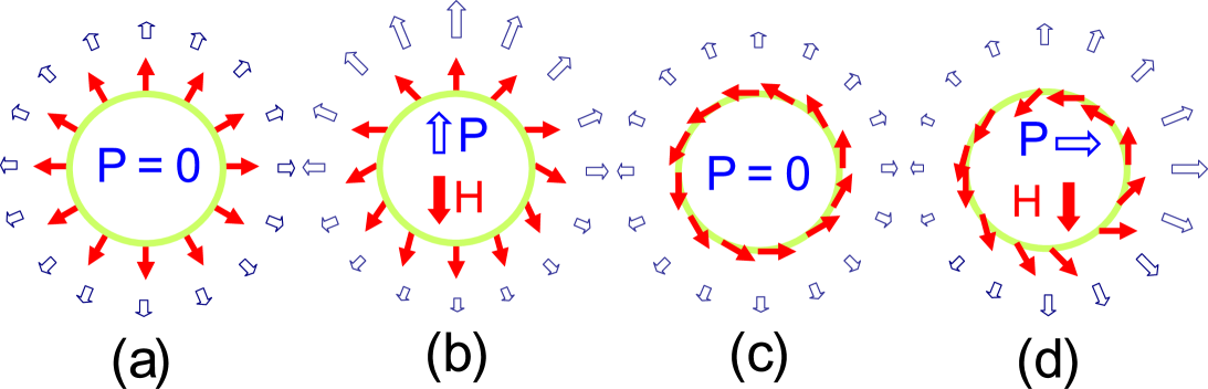
We begin by considering the magnetoelectric response of a single spin vortex (Fig. 1a). This can be viewed as a magnetic spiral rolled into a circle, and so we can use the results from spiral multiferroics to analyze its magnetoelectric response. The magnetically induced ferroelectric polarization in spiral multiferroics is described by
| (4) |
where is the axis around which the spins rotate and is the spiral wavevectorMostovoy (2006). In our context, this coupling induces an inhomogeneous electric polarization locally oriented along the radial direction, so that the net polarization of the vortex is zero. A magnetic field applied in the plane leads to a non-uniform rotation of spins in the vortex, which results in a nonzero net electric polarization proportional to the magnetic field (see Fig. 1b). The spin vortex shown in Fig. 1a has a diagonal magnetoelectric tensor, with magnetization induced parallel to the applied electric field, while for the vortex shown in Fig. 1c an applied magnetic field induces a perpendicular electric polarization and the magnetoelectric tensor is antisymmetric (see Fig. 1d). These conclusions are actually independent of the mechanism of magnetoelectric coupling and generally follow from the fact that the vortices shown in Figs. 1a and 1c have respectively a monopole moment and a toroidal moment Spaldin et al. .
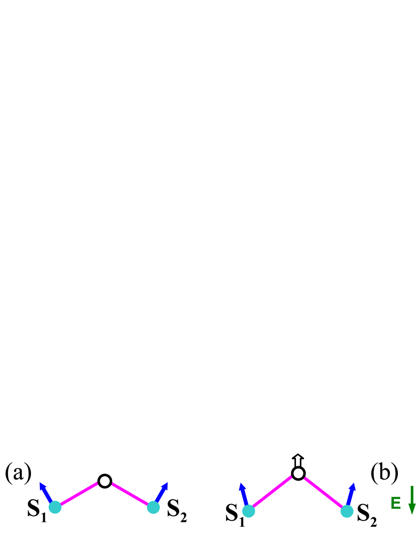
Next we analyze the spin-lattice coupling resulting from the dependence of the Heisenberg superexchange interaction between spins on their relative positions. Consider a three-atom unit consisting of two magnetic transition metal ions connected by a ligand such as oxygen that mediates superexchange (Fig. 2). Due to charge differences, the cations and ligand shift in opposite directions under application of an electric field. The exchange constant coupling the spins depends on the amplitude of the relative shifts through the changes in the metal-oxygen distance and the metal-oxygen-metal bond angle . According to the Anderson-Kanamori-Goodenough rulesAnderson (1963), the exchange is antiferromagnetic () for and ferromagnetic () for . Experiments varying A-site cation size in transition metal oxides have shown that the crossover from ferromagnetic to antiferromagnetic coupling is continuousSubramanian et al. (1999). Therefore, the total magnetization of the unit can be modified by applying an electric field; conversely changes in spin orientation will affect its electric dipole moment.
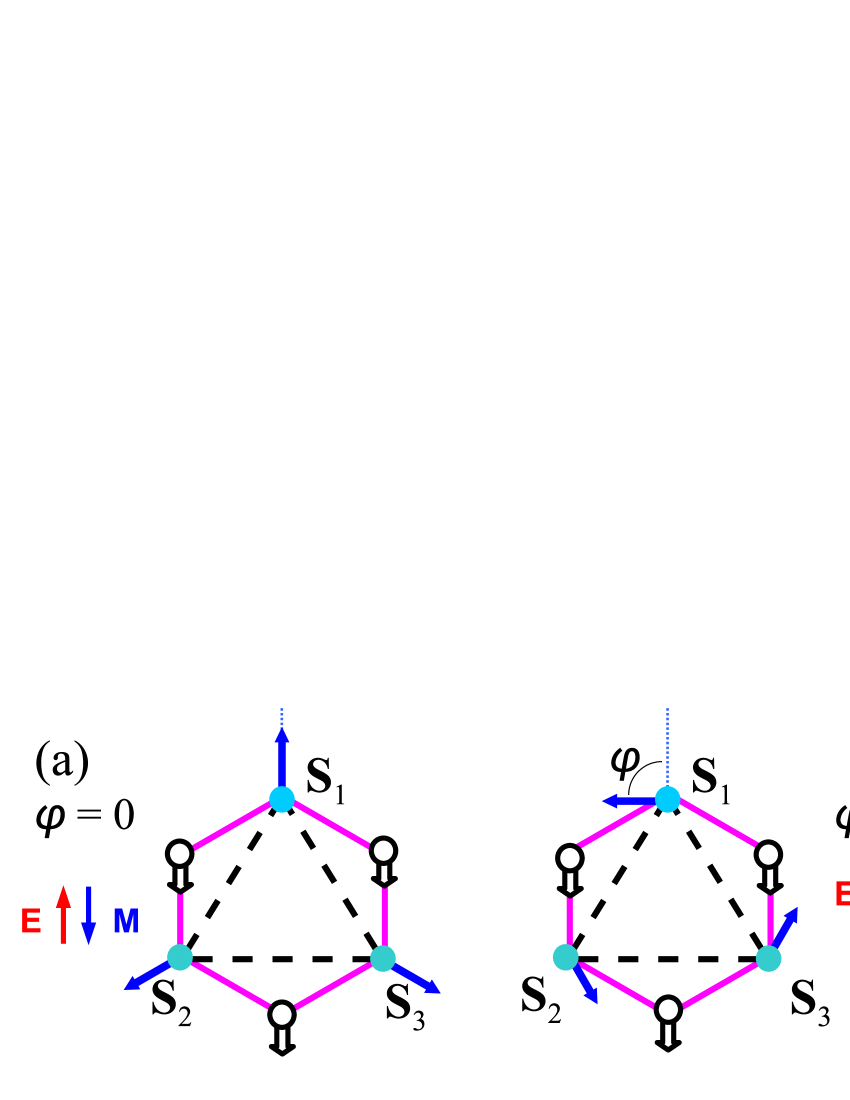
Now we combine these two concepts to form a periodic array of magnetic vortices in which the magnetic moments are coupled through superexchange, and show that the combination leads to a large magnetoelectric response. The macroscopic magnetoelectric response of an array of magnetic vortices is proportional to the vortex density. Therefore we choose the smallest possible magnetic vortex as our building block: a triangle of antiferromagnetically coupled spins, in which the angle between spins in the lowest-energy state is 120∘ (Fig. 3a). Using transition metal (TM) ions to provide the spins, and incorporating oxygen ligands between them (Fig. 3a), leads to superexchange spin-spin interactions. Upon application of an electric field, the shifts of the oxygen anions relative to the positive TM ions induce changes in the Heisenberg exchange energy, changing the spin canting angles and resulting in a nonzero magnetization. The symmetry of the magnetoelectric response of the triangle is identical to that of the magnetic vortices of Fig. 1, with the form of the in-plane magnetoelectric tensor constrained by its C3v symmetry to
| (5) |
Here is the angle between spins and the vectors directed from the triangle center to the corresponding vertex. In particular, (Fig. 3a) leads to , so that for the induced magnetization is antiparallel to the electric field ; for , is perpendicular to (Fig. 3b).
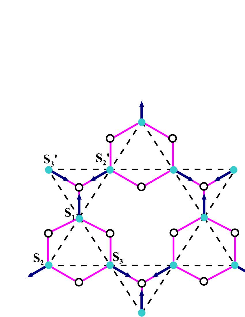
To transform the concepts outlined above into a model material with a three-dimensional periodic structure, we begin with planes of Mn atoms situated on the vertices of a Kagomé lattice and assume that their spins form the structure with zero wave vector (see Fig. 4), as observed e.g. in iron jarosite KFe3(OH)6(SO4)2Grohol et al. (2005). At first glance, such a spin lattice would yield no magnetoelectric response because spins in the vortices formed at “up” and “down” triangles are oriented in opposite senses ( and ). However, when oxygen ions are positioned outside the “up” triangles and inside the “down” triangles, the sign of magnetoelectric coupling [ in Eq. 5] also alternates and the contributions of all triangles to have the same sign. This can be understood by comparing the magnetoelectric response of the and spin pairs and noting that, for fixed bond lengths and angle, only the scalar product of spins is important in Heisenberg exchange.
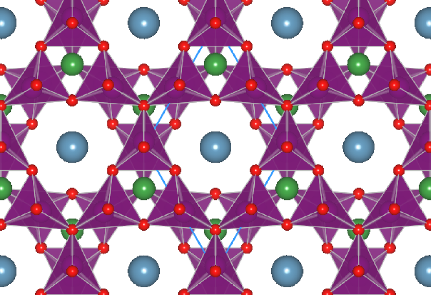
The two-dimensional plane shown in Fig. 4 has a similar structure to the MnO layers of the experimentally realized YMnO3 structureVan Aken et al. (2004), which consists of a connected mesh of oxygen trigonal bipyramids with Mn atoms at their centers. Using this structure as motivation, we extend our two-dimensional MnO planes to a three-dimensional periodic structure and introduce counter-ions (Ca and Al) in the voids of the lattice so that the correct charge balance is attained. To ensure that the sign of magnetoelectric response is the same for all layers, the neighboring MnO planes are rotated by 180∘ with respect to each other (Fig. 5). This reverses the positioning of oxygen ions with respect to the “up” and “down” spin triangles in the next layer, which compensates the reversal of the spin direction that must result from the antiferromagnetic interlayer coupling provided by the 180∘ connections through the apical oxygen atoms. Our resulting ‘KITPite’ structure111After the Kavli Institute for Theoretical Physics, where this structure was first suggested by the authors., with chemical formula CaAlMn3O7, correctly breaks and symmetry; in addition the apical oxygen ions between the MnO layers are centers of combined symmetry.
Finally, to assess the strength of the magnetoelectric response of the model material introduced in the previous section, we turn to first principles calculations employing plane-wave density functional theory (DFT) as implemented in VASPKresse and Furthmüller (1996). We use PAW potentials for core-valence separationKresse and Joubert (1999), and include non-collinear magnetism for the valence electrons. We approximate the exchange-correlation part of the Kohn-Sham potential using the rotationally invariant form of the LSDA in the fully localized limitLiechtenstein et al. (1995), with the Hubbard applied only to the Mn electrons ( eV and eVYang et al. (1999)). It is important to note that we deliberately do not include spin-orbit coupling in our calculations so as to ensure that our calculated magnetoelectric response arises entirely from the superexchange coupling. As a result, the pseudoscalar and toroidal spin arrangements (Figs. 3 (a) and (b)) are degenerate, and we are unable to determine whether is diagonal or antisymmetric.
We first relax the structure in the absence of an electric field by optimizing the ionic coordinates to find the lowest-energy state with the constraint that the trigonal bipyramids are prevented from tilting. This constraint preserves the Kagomé structure of the MnO planes which is essential for demonstrating the superexchange magnetoelectricity of this model. The resulting structure is shown in Fig. 5. Our calculated valence electronic structure is, as expected, similar to that of YMnO3Van Aken et al. (2004): The formal Mn charge is , with four majority electrons per Mn (, , and ), and an unoccupied minority channel providing a local moment of /Mn.
Subsequently, we apply an electric field and calculate the linear response of the ions, which is sufficient for computing the linear magnetoelectric coefficient. The force on an ion upon application of an external electric field is determined by the Born effective charge tensor, , through , where is the force, is the applied electric field, is an index denoting the ion, and are spatial directions. The summation convention for repeated indices is once again employed. All elements of the tensor are computed through derivatives of the bulk polarization , where is calculated using the Berry-phase approachKing-Smith and Vanderbilt (1993) for a small displacement in all degrees of freedom individually. The method is close to that employed by ÍñiguezÍñiguez (2008).
In order to obtain the first-order ionic response to the field, we use the force-constant matrix . Then, to linear order, the ionic displacements for a given force are found by inverting the force-constant matrix through , so that the ionic response to an applied electric field is . Finally, the total magnetization is calculated as a function of , yielding the linear magnetoelectric coupling constant.
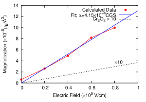
Fig. 6 shows the calculated magnitude of the induced magnetization as a function of applied electric field. With a field of V/cm, the ionic response leads to an average displacement of Mn atoms of Å in the direction of the field and of O atoms of Å against the field. The Born effective charges, , have an in-plane average magnitude of for Mn and for O. Using an equilibrium spin arrangement as shown in Fig. 4, the spins and rotate by and respectively, leading to a magnetoelectric coupling coefficient of JT-1V-1m-2. Transformation to regularized CGS units yields . For a benchmark, we compare to the magnetoelectric response of Cr2O3 computed also within density functional theoryÍñiguez (2008), in Gaussian units (in good agreement with the experimental value). Hence, our model system has a magnetoelectric coupling around 30 times larger than that of Cr2O3. Since the spin-orbit coupling was not considered in this work, magnetic anisotropies that determine the angle were neglected. We therefore cannot predict whether KITPite would carry a pseudoscalar or a toroidal moment in the ground state. However, the strength of the magnetoelectric coupling resulting from Heisenberg superexchange [ in Eq.(5)] is insensitive to .
In conclusion, we have combined the concepts of magnetically induced polarization in magnetic vortices with lattice-mediated coupling through the superexchange mechanism to demonstrate strong magnetoelectric coupling in geometrically frustrated antiferromagnets. We showed that such a mechanism can be studied using modern density-functional theory approaches with non-collinear spin density functionals and augmented with linear-response methods, and we explicitly calculated the magnetoelectric coupling of a model transition metal oxide. While the linear magnetoelectric response of our model compound is larger than that of any known single phase material, we anticipate that many further improvements are possible: In particular materials with larger polarizability through increased s or reduced rigidity would be promising. We hope that this study will stimulate the search for additional novel strongly-coupled magnetoelectric materials.
Acknowledgements.
This work was initiated during the research program on Moments and Multiplets in Mott Materials at the Kavli Institute for Theoretical Physics at UC Santa Barbara under the NSF grant No. PHY05-51164. Delaney and Spaldin were supported by the National Science Foundation under Award No. DMR-0605852. Calculations were performed at the UCSB California Nanosystems Institute (CNSI) with facilities provided by NSF Award No. CHE-0321368 and Hewlett-Packard, at the San Diego Supercomputer Center, and at the National Center for Supercomputer Applications.References
- Landau and Lifshitz (1960) L. D. Landau and E. M. Lifshitz, Electrodynamics of Continuous Media (Addison-Wesley, Reading, MA, USA, 1960).
- Fiebig (2005) M. Fiebig, J. Phys. D: Appl. Phys. 38, R123 (2005).
- Newnham et al. (1978) R. E. Newnham, J. J. Kramer, W. A. Schulze, and L. E. Cross, J. Appl. Phys. 49, 12 (1978).
- Kimura et al. (2003) T. Kimura, T. Goto, H. Shintani, K. Ishizaka, T. Arima, and Y. Tokura, Nature 426, 55 (2003).
- Goto et al. (2004) T. Goto, T. Kimura, G. Lawes, A. P. Ramirez, and Y. Tokura, Phys. Rev. Lett. 92, 257201 (2004).
- Katsura et al. (2005) H. Katsura, N. Nagaosa, and A. V. Balatsky, Phys. Rev. Lett. 95, 057205 (2005).
- Sergienko and Dagotto (2006) I. A. Sergienko and E. Dagotto, Phys. Rev. B 73, 094434 (2006).
- Sergienko et al. (2006) I. A. Sergienko, C. Sen, and E. Dagotto, Phys. Rev. Lett. 97, 227204 (2006).
- Picozzi et al. (2007) S. Picozzi, K. Yamaguchi, B. Sanyal, I. A. Sergienko, and E. Dagotto, Phys. Rev. Lett. 99, 227201 (2007).
- Mostovoy (2006) M. Mostovoy, Phys. Rev. Lett. 96, 067601 (2006).
- (11) N. A. Spaldin, M. Fiebig, and M. Mostovoy, J. Phys.: Condens. Matter in press (????).
- Anderson (1963) P. W. Anderson, Magnetism, vol. 1 (Academic Press, New York, 1963).
- Subramanian et al. (1999) M. A. Subramanian, A. P. Ramirez, and W. J. Marshall, Phys. Rev. Lett. 82, 1558 (1999).
- Grohol et al. (2005) D. Grohol, K. Matan, J.-H. Cho, S.-H. Lee, J. W. Lynn, D. G. Nocera, and Y. S. Lee, Nature Materials 4, 323 (2005).
- Van Aken et al. (2004) B. B. Van Aken, T. T. M. Palstra, A. Filippetti, and N. A. Spaldin, Nature Materials 3, 164 (2004).
- Kresse and Furthmüller (1996) G. Kresse and J. Furthmüller, Phys. Rev. B 54, 11169 (1996).
- Kresse and Joubert (1999) G. Kresse and D. Joubert, Phys. Rev. B 59, 1758 (1999).
- Liechtenstein et al. (1995) A. I. Liechtenstein, V. I. Anisimov, and J. Zaanen, Phys. Rev. B 52, R5467 (1995).
- Yang et al. (1999) Z. Yang, Z. Huang, L. Ye, and X. Xie, Phys. Rev. B 60, 15674 (1999).
- King-Smith and Vanderbilt (1993) R. D. King-Smith and D. Vanderbilt, Phys. Rev. B 47, 1651 (1993).
- Íñiguez (2008) J. Íñiguez, Phys. Rev. Lett. 101, 117201 (2008).