The Time Projection Chamber for the ALICE Experiment
Abstract
The Time Projection Chamber of the ALICE Experiment has been installed in the experimental setup in the underground area at the Large Hadron Collider at CERN in Geneva. The Alice TPC ReadOut (ALTRO) chip implements intelligent signal processing on the Front-End-Electronics. During the years of 2007 and 2008 commissioning and calibration of the TPC have been carried out with cosmic rays, radioactive Krypton isotopes and with tracks produced by a UV laser system. In addition to these in this publication we present first results on energy loss measurements and on the momentum resolution.
I INTRODUCTION
ALICE alice will search for evidence of the quark-gluon plasma—a state of matter which is believed to have existed just after the Big Bang—in head-on collisions of lead-ions at the LHC. It will also be used to study the properties of proton-proton collisions. The trajectories of thousands of charged particles produced in central lead-lead collisions have to be measured and the particles have to be identified. To serve these tasks, the largest Time Projection Chamber (TPC) in the world was installed in the central barrel of ALICE tpctdr .
The ALICE TPC provides track finding, momentum measurement and PID at transverse momenta 0.1 100 GeV/c and in the pseudorapidity range . The requirements in the extreme multiplicities of ion collisions at the LHC are however very challenging: A good tracking efficiency ( %) and a momentum resolution of 1 % at 2 GeV/c (TPC only), 10 % at 50 GeV/c (TPC only) or 3.5 % at 100 GeV/c (TPC together with the inner tracking system and Transition Radiation Detector TRD). The d/d resolution has to be better than % and the rate capability has to be Hz for central lead-lead collsions and kHz for proton-proton collsions.
The TPC is cylindrical in shape with an active radial range from 85 to 247 cm and an overall length of 500 cm. A central high voltage electrode divides the volume into two drift regions of 250 cm length. As readout chambers (ROCs) multiwire proportional chambers with cathode pad readout are mounted in 18 trapezoidal sectors in both endplates. Each sector is segmented in two ROCs (Inner and outer - IROC and OROC) with a pad (and wire) geometry optimized to the expected occupancy (below 40% at the maximum design multiplicity of d/d=8000). In total the TPC has 557 568 pads with three sizes; the smallest pads are mm2. A light cold drift gas (Ne, CO2, N2) was chosen because of the small diffusion and low multiple scattering chilo . It also has a low number of ionisation electrons per unit length, which together with the rather high ion mobility helps to minimise field distortions due to space charge for running at high luminocities with high rates of secondary charged particles. However, the low ionisation energy loss in combination with the chosen pad sizes requires a rather large gas gain of up to 104 in order to meet the requirement of a good ratio of .
The construction and assembly of the TPC was completed in 2006. After an extensive (pre)commissioning phase on the surface the TPC was lowered into the underground experimental area and transferred into the large solenoidal magnet in January 2007, where commissioning of all service infrastructure and readout electronics took place. Since then the TPC was calibrated with laser and cosmics tracks and with radioactive Krypton decays in the active gas volume. The different calibration procedures are described in Section III.
The task of large acceptance tracking in the ALICE TPC is similar to that encountered in previous heavy-ion experiments at the SPS and RHIC. However, the extreme multiplicities of ion collisions at the LHC set qualitatively and quantitatively new demands. This made indispensable the design of a new read out chip, which will be described briefly in the following section.
II ALICE TPC READOUT CHIP
The Alice TPC ReadOut (ALTRO) chip musa ; altro implements a 10 bit, 10 MSPS ADC and digital filtering circuits in four stages for 16 channels. The first stage implements a baseline correction in order to prepare the signal for the tail cancellation; low frequency perturbations and systematic effects are removed. The tail cancellation block is used to suppress the tails of the pulses within 1 s after the peak with very good accuracy. The filter coefficients for each channel are fully programmable and thus the circuit is able to cancel a wide range of signal tail shapes. The third processing block applies a baseline correction scheme based on a moving average filter, removing non-systematic perturbations of the baseline that are superimposed on the signal. At the output of this block, the signal baseline is constant with an accuracy of 1 ADC count, which makes possible a very efficient zero-suppression. This is important because it largely reduces the data volume while keeping the interesting signals. The readout is finally performed out of the on-detector event buffers upon receipt of a level 2 trigger accept signal.
III TPC CALIBRATION
After the comissioning of the overall system is finished important tasks are calibration and alignment. We use data that are aquired in dedicated calibration runs. Some of the calibration methods used are described in the following.
III.1 PEDESTALS AND NOISE
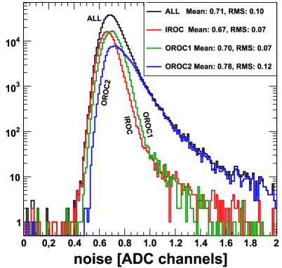
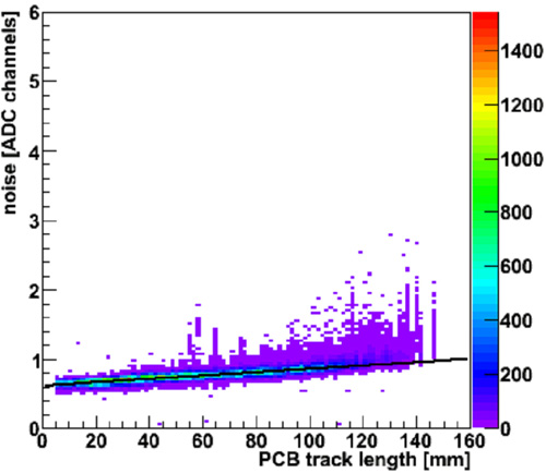
Pedestal runs are taken periodically. A histogram of the overall system noise in all TPC readout channels is shown in Fig. 2. Noise is defined as r.m.s. of the baseline. The present value is clearly better than the design value of 1 ADC count, the mean noise is about 0.7 ADC counts and as Fig. 2 shows the noise is correlated to the capacitances of the individual readout traces. This shows that the system noise close to the natural limit. The pedestal values are very constant with time.
III.2 ISOCHRONICITY
Small variations in the signal arrival time () are due to chip-to-chip variations of the signal shaping and due to signal delays. They can be studied and calibrated using pulses injected into the cathode wire grid of the ROCs. The induced signals are read out from all pads and the time position and amplitude of the pulser signals are analysed event-by-event.

III.3 CALIBRATION WITH THE LASER SYSTEM
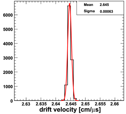
A Nd:YAG laser running at 266 nm is used to generate tracks in the TPC by sending in 168 laser rays arranged in 4 planes along the beam direction on both sides of the TPC laser . These can be used to align adjacent ROCs, determine electric field distortions due to space charge at high track densities and to measure effects. In addition, scattered laser light ejects photoelectrons from the central electrode (CE). All readout pads receive this signal at a certain characteristic time corresponding to the drift length and velocity. This information can also be used for alignment and for drift velocity and gain calibration. Fig. 4 shows the mean drift velocity calculated from the central electrode signals. The relative resolution is , which is sufficient for calibration of the data in the physics analysis. The behaviour with time is monitored with a dedicated drift velocity monitor. The electrostatic geometry of the ROCs was not yet tuned when the present data were taken. We expect an additional improvement.
III.4 GAIN AND ENERGY LOSS CALIBRATION
Due to geometric imperfections the ROC gain is not equal for all readout pads in the TPC. For gain calibration (equalisation) three different sources are used: Krypton data, laser (CE) data and pulser data. The Krypton method was used already by the NA49 experiment na49 . Radioactive Krypton isotopes are injected in the TPC drift gas. The charge deposit (with several peaks up to 42 keV) is measured at random positions and random drift times. The dynamic range of the ADC in the ALTRO chips allows to do this at the nominal gain. Thus we are able to directly calibrate the gain of the ROCs. The relative gain variations withing a ROC are about 7 % (). The variations from ROC to ROC for the outer chambers (OROCs) are about 8 %. (r.m.s.), as shown in Fig. 4.
IV PRELIMINARY RESULTS FROM THE ANALYSIS OF COSMIC TRACK DATA
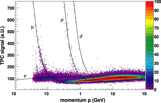
Analysing cosmic tracks in the TPC gives a first idea on how the TPC will perform when the LHC provides collisions. We obtained first results on energy loss (d/d) and momentum resolution by comparing the two parts of tracks of the same event reconstructed in the upper and lower half of the TPC. The magnetic field was set to T. Fig. 5 shows the energy loss as a function of momentum. The gain calibration was done using the Krypton method described in Section III.4. This first analysis shows that the d/d-resolution is better than 6 %.

Fig. 6 shows the momentum resolution obtained with cosmic ray tracks for the TPC. The difference between the upper and lower part of each cosmic ray track is analyzed to determine the momentum resolution as a function of momentum. We used data from one side of the TPC and divided the result by in order to obtain a single particle resolution. No calibration was applied on the data; especially the calibration is expected to improve the resolution.
V SUMMARY
The largest TPC ever built is at the heart of the ALICE Experiment. For the TPC readout the ALTRO chip is used, which implements intelligent signal processing and data volume reduction at high occupancy and rate on the Front-End-Electronics. The TPC has been fully commissioned in the period from 2006 to summer 2008 and is now operating under nominal conditions at a gain of about 8000. The overall system noise is close to the natural limit. Analysis of data taken with a cosmic ray trigger gives a good indication of how the data from collisions will look like. We currently extract the various calibration parameters from cosmic, laser and pulser data. The TPC is ready for collisions.
References
- (1) The ALICE Collaboration, K. Aamodt et al., “The ALICE Experiment at the CERN LHC”, JINST 3 (2008) S08002.
- (2) The ALICE Collaboration, “ALICE TPC Technical Design Report”, CERN/LHCC 2000-001, ALICE TDR 7, 7 January 2000.
- (3) C. Garabatos et al., Proceedings of the 10th International Vienna Conference on Instrumentation“The ALICE TPC”, NIM A535 (2004) 197-200.
- (4) L. Musa et al., “The ALTRO chip: a 16-channel A/D converter and digital processor for gas detectors”, IEEE Trans. Nucl. Sci., November 2003.
- (5) B. Mota et al., “Performance of the ALTRO chip on data aquired on an ALICE TPC prototype”, NIM A 535 (2004) 500-505.
- (6) G. Renault et al., “The Laser of the ALICE Time Projection Chamber”, Int. J. Mod. Phys. E (2007) 2413-2418; nucl-ex/0703042.
- (7) S. Wenig et al., “Performance of the large-scale TPC system in the CERN heavy ion experiment NA49”, NIM A 409 (1998) 100-104.