In-situ measurement of the permittivity of helium using microwave NbN resonators
Abstract
By measuring the electrical transport properties of superconducting NbN quarter-wave resonators in direct contact with a helium bath, we have demonstrated a high-speed and spatially sensitive sensor for the permittivity of helium. In our implementation a 10-3 mm3 sensing volume is measured with a bandwidth of 300 kHz in the temperature range 1.8 to 8.8 K. The minimum detectable change of the permittivity of helium is calculated to be 6 /Hz1/2 with a sensitivity of order /Hz1/2 easily achievable. Potential applications include operation as a fast, localized helium thermometer and as a transducer in superfluid hydrodynamic experiments.
pacs:
07.20.Mc, 52.70.Gw, 85.25.QcWith their ease of fabrication, high quality factors and the wide availability of measurement electronics, superconducting microwave resonators have recently emerged as ideal systems for studying mesoscopic physics. Their applications are widespread and include electromagnetic radiation detectors, Day et al. (2003); Doyle et al. (2008) electromechanical transducers, Flowers-Jacobs et al. (2007); Regal et al. (2008) and quantum computing circuit elements.Wallraff et al. (2004); Vion et al. (2002); Hofheinz et al. (2008) In realizing a superconducting resonator, it is often convenient to use a high-frequency transmission line with a planar geometry, enabling straight forward integration with other on-chip devices. Typical designs include microstrip or coplanar waveguide (CPW). However, these geometries are very sensitive to their environment and it is necessary to minimize dielectric loss in order to achieve optimal performance. This can be accomplished, for example, by utilizing a low loss dielectric such as sapphire for the support substrate and performing the experiment in vacuum.
While dissipation of energy in the surrounding dielectric usually limits performance of a superconducting resonator, it is also possible to utilize this feature to probe intrinsic material properties. For example, by fabricating a series of half-wavelength CPW resonators coated with a variety of dielectrics, the high-frequency, low-temperature and low-energy properties of common insulating materials have recently been reported. O’Connell et al. (2008) In a similar study, quarter-wavelength CPW resonators coated with varying thicknesses of SiOx were used to investigate the noise properties of thin film dielectrics. Barends et al. (2008a)


Here we demonstrate the ability of CPW superconducting resonators to sensitively detect changes in the permittivity of surrounding helium at low temperatures (1.8 to 8.8 K). Previous measurements have relied on large-volume cavity resonances (1 mm3) or audio-frequency measurements of parallel-plate capacitors ( kHz), thus excluding high-speed localized measurements.Greenkemper and Hagen (1950); Niemela and Donnelly (1995) In contrast, the small sensing volume (10-3 mm3), open geometry and tunable bandwidth of CPW resonators are ideally suited to fast, localized measurements. The high spatial sensitivity can also be made to extend over large detection volumes by frequency-multiplexing an array of resonators. This could enable, for example, measurement of local fluctuations in quantum hydrodynamic experiments similar to previous measurements, Roche et al. (2007) but with increased volumetric and temporal resolution.
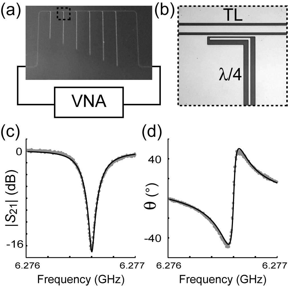
A diagram of our experiment is shown in Fig. 1. The fabrication of quarter-wave superconducting resonators has been previously reported.Mazin (2004); Barends et al. (2008b) Briefly, 150 nm of B1-cubic NbN phase was sputter-deposited epitaxially on a 430-m-thick M-plane sapphire substrate.de Lamaëstre et al. (2007) This was then patterned using photo-lithography and subsequent reactive-ion etching in a SF6/O2 plasma. NbN was chosen for its high of 15 K to enable a large temperature range for measurement. The wafer was then mounted on a copper-clad board and wire-bonded to a 50- transmission line. Multiple bonds were made in order to reduce the parasitic reactance of the wire bonds. The board was enclosed in a custom-designed microwave package and attached to stainless-steel coaxial cables at the cold stage of a helium cryostat. No vacuum space was used in order to allow direct contact between the helium bath and the NbN resonators.
The cryostat was immersed in liquid helium and electrical transport data was taken with a vector network analyzer. The amplitude for a typical transmission measurement is shown in Fig. 1(c) and the corresponding phase in Fig. 1(d). Inspection of the measured data reveals an asymmetry in the transmission about the resonant frequency . The usual explanation for this asymmetry is a parasitic inductance associated with the bond wires. Doyle et al. (2008); Krems et al. (1995) To account for this effect we have modeled our resonant circuit as a shunt impedance connected to the source and detection ports of the network analyzer ( = 50 ) by parasitic reactances and . includes the coupling capacitance between the resonator and transmission line in addition to the intrinsic resonator impedance. The Thévenin and Norton equivalent circuits are shown in Fig. 2. Using this circuit model, we can calculate the complex scattering parameter
| (1) |
where and are assumed to be frequency independent for a given resonator as the fractional change in the frequency (/) is small over the measurement bandwidth. The loaded resonator impedance at a frequency is given byPozar (2005); Mazin (2004)
| (2) |
where is the intrinsic quality factor of the resonator and is the external quality factor due to coupling with the measurement electronics. The measurement’s loaded quality factor is given by = + .
We have used Eq. (1) to fit the data for our resonators. While the parasitic reactances do not change significantly in the bandwidth of a single resonator, they will in general depend on frequency and hence can be different for each resonator. However, for any given resonator these fit parameters are found to not vary substantially with temperature and in nearly all cases, . This matches well with the assumption that the asymmetry in about is largely due to the bond wires. For the resonance shown in Fig. 1 a typical value of was found.

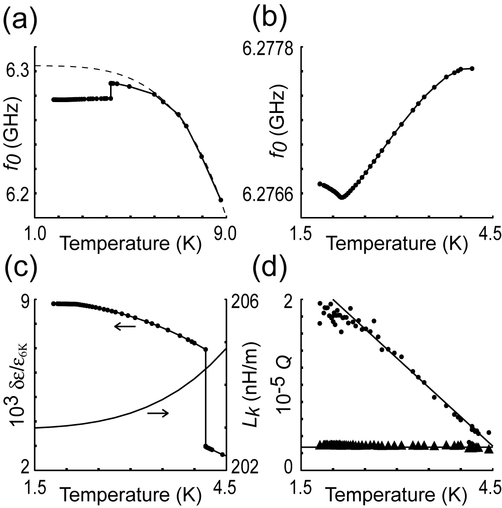
The extracted resonance frequency is shown as a function of temperature for a resonator of length 4540 m in Fig. 3(a) and below 4.2 K in Fig. 3(b). The structure of this data is governed byPozar (2005); Barends et al. (2008b)
| (3) |
where is the resonator’s length, is the effective permittivity of the resonator, and , and are the resonator’s kinetic inductance, geometric inductance and capacitance respectively, each expressed as a reactance per unit length. The average kinetic inductance per unit length is given by Schmidt (1997)
| (4) |
where is the local supercurrent density; is the total current; , the London penetration depth, is given by the empirical formula ; and the integral is taken over the volume of the superconductor. Since the magnetic penetration depth of NbN is of the order of our film thickness ( nm),Lamura et al. (2002) it is reasonable to assume a uniform supercurrent density if we neglect fringing effects. In this case, the kinetic inductance reduces to , where A is the cross-sectional area of the NbN film.
At temperatures appreciably above the boiling point of helium and at standard pressure, the dielectric permittivity is temperature insensitive. In this regime, the measured change in is dominated by . A fit of Eq. (3) to the data above 6 K assuming constant permittivity is shown in Fig. 3(a). The temperature-independent geometric inductance and capacitance were determined utilizing finite-element software to be 661 nH/m and 93 pF/m, respectively. From this fit, we find nm and K for the NbN film, consistent with previous measurement. Lamura et al. (2002) For temperatures below 6 K, the data deviates from the fit due to changes in the dielectric. The ratio of the fitted curve () to the measured data () allows determination of the permittivity through , where is the fractional change in the permittivity measured from the permittivity at 6 K. Fig. 3(c) displays the temperature dependence of and determined from this analysis.
It is useful to estimate the sensitivity of our NbN quarter-wave resonators to the permittivity of helium . From Eq. (3), at low temperatures and thus for small changes in the permittivity, . For CPW, the effective permittivity is approximately the average of the environmental and substrate permittivities, or in our case, . In terms of small changes in the permittivity of helium, . The change in the measurement phase for small changes in frequency about resonance is given by the relationship . The phase uncertainty of an amplifier with a noise temperature is (radians/Hz1/2), where is the measurement signal power.Mazin (2004) Combining these, we find for the sensitivity
| (5) |
assuming the limiting noise contribution is from the first stage amplifier. Using , , dBm, , and an amplifier noise temperature of 290 K, we calculate a sensitivity of /Hz1/2 for our measurement. By utilizing a cryogenic amplifier, increasing the measurement signal power, and decreasing the coupling, we estimate a sensitivity of order /Hz1/2 can easily be achieved.
In conclusion, we have demonstrated a small-volume (10-3 mm3), high-speed ( 3 s) technique for in-situ measurement of the permittivity of helium. Potential applications of this device include operation as an exquisite helium thermometer or as a spatially-sensitive transducer in superfluid hydrodynamic experiments.
This work was supported by the EuroSQIP project and RTRA “Nanosciences Grenoble.”
References
- Day et al. (2003) P. K. Day, H. G. LeDuc, B. A. Mazin, A. Vayonakis, and J. Zmuidzinas, Nature 425, 817 (2003).
- Doyle et al. (2008) S. Doyle, P. Mauskopf, J. Naylon, A. Porch, and C. Duncombe, J. Low Temp. Phys. 151, 530 (2008).
- Flowers-Jacobs et al. (2007) N. E. Flowers-Jacobs, D. R. Schmidt, and K. W. Lehnert, Phys. Rev. Lett. 98, 096804 (2007).
- Regal et al. (2008) C. A. Regal, J. D. Teufel, and K. W. Lehnert, Nat. Phys. 4, 555 (2008).
- Wallraff et al. (2004) A. Wallraff, D. I. Schuster, A. Blais, L. Frunzio, R.-S. Huang, J. Majer, S. Kumar, S. M. Girvin, and R. J. Schoelkopf, Nature 431, 162 (2004).
- Vion et al. (2002) D. Vion, A. Aassime, A. Cottet, P. Joyez, H. Pothier, C. Urbina, D. Esteve, and M. H. Devoret, Science 296, 886 (2002).
- Hofheinz et al. (2008) M. Hofheinz, E. M. Weig, M. Ansmann, R. C. Bialczak, E. Lucero, M. Neeley, A. D. O’Connell, H. Wang, J. M. Martinis, and A. N. Cleland, Nature 454, 310 (2008).
- O’Connell et al. (2008) A. D. O’Connell, M. Ansmann, R. C. Bialczak, M. Hofheinz, N. Katz, E. Lucero, C. McKenney, M. Neeley, H. Wang, E. M. Weig, A. N. Cleland, and J. M. Martinis, Appl. Phys. Lett. 92, 112903 (2008).
- Barends et al. (2008a) R. Barends, H. L. Hortensius, T. Zijlstra, J. J. A. Baselmans, S. J. C. Yates, J. R. Gao, and T. M. Klapwijk, Appl. Phys. Lett. 92, 223502 (2008a).
- Greenkemper and Hagen (1950) C. J. Greenkemper and J. P. Hagen, Phys. Rev. 80, 89 (1950).
- Niemela and Donnelly (1995) J. J. Niemela and R. J. Donnelly, J. Low Temp. Phys. 98, 1 (1995).
- Roche et al. (2007) P.-E. Roche, P. Diribarne, T. Didelot, O. Francais, L. Rousseau, and H. Willaime, Europhysics Lett. 77, 66002 (2007).
- Mazin (2004) B. A. Mazin, Microwave kinetic inductance detectors (Caltech, Pasadena, 2004).
- Barends et al. (2008b) R. Barends, J. J. A. Baselmans, S. J. C. Yates, J. R. Gao, J. N. Hovenier, and T. M. Klapwijk, Phys. Rev. Lett. 100, 257002 (2008b).
- de Lamaëstre et al. (2007) R. E. de Lamaëstre, P. Odier, and J.-C. Villégier, Applied Physics Letters 91, 232501 (2007).
- Krems et al. (1995) T. Krems, W. Haydl, L. Verweyen, M. Schlechtweg, H. Massler, and J. Rudiger, Electrical Performance of Electronic Packaging p. 178 (IEEE, Portland, 1995).
- Pozar (2005) D. M. Pozar, Microwave Engineering (Wiley, Hoboken, 2005).
- Schmidt (1997) V. V. Schmidt, The Physics of Superconductors (Springer, Berlin, 1997).
- Lamura et al. (2002) G. Lamura, J.-C. Villégier, A. Gauzzi, J. Le Cochec, J.-Y. Laval, B. Plaçais, N. Hadacek, and J. Bok, Phys. Rev. B 65, 104507 (2002).