Current-pulse induced magnetic switching in standard and nonstandard spin-valves
Abstract
Magnetization switching due to a current-pulse in symmetric and asymmetric spin valves is studied theoretically within the macrospin model. The switching process and the corresponding switching parameters are shown to depend significantly on the pulse duration and also on the interplay of the torques due to spin transfer and external magnetic field. This interplay leads to peculiar features in the corresponding phase diagram. These features in standard spin valves, where the spin transfer torque stabilizes one of the magnetic configurations (either parallel or antiparallel) and destabilizes the opposite one, differ from those in nonstandard (asymmetric) spin valves, where both collinear configurations are stable for one current orientation and unstable for the opposite one. Following this we propose a scheme of ultrafast current-induced switching in nonstandard spin valves, based on a sequence of two current pulses.
pacs:
67.30.hj,75.60.Jk,75.70.CnI Introduction
The possibility of current-induced magnetic switching (CIMS) in multilayer structures has been introduced by Slonczewski Slonczewski (1996) and Berger Berger (1996). They pointed out that spin polarized current passing through a multilayer consisting of two ferromagnetic layers separated by a nonmagnetic spacer can exert a torque on the local magnetic moments in ferromagnetic layers. In case of commonly used (standard) spin valves, this torque can switch the system between parallel (P) and antiparallel (AP) alignments of the layers’ magnetic moments. Indeed, the CIMS has been confirmed experimentally in many spin valve structures Tsoi et al. (1998); Myers et al. (1999); Katine et al. (1999); Kiselev et al. (2003).
In order to meet the technological demands for applications, designing of bistable magnetic spin valve devices that could be fast switched by electric current only is highly desired. Accordingly, several subtle switching schemes aimed at speeding up the switching process and lowering the energy costs have been developed for various magnetic multilayer structures. It has been shown that proper optimization of the current pulse parameters (amplitude, duration, frequency, etc.) can finally result in ultrafast, single-step, switching Serrano-Guisan et al. (2008); Garzon et al. (2008).
Current-induced dynamics in spin valves is governed by spin-transfer torque (STT), particularly by its magnitude and dependence on the angle between magnetization vectors of the reference and sensing magnetic layers. Such an angular variation depends mainly on the type of electron transport through the spin valve. Recently, STT in the diffusive transport regime draws more attention. It has been demonstrated Urazhdin and Button (2008), that spin diffusion in various types of polarizing layer can strongly influence the current-induced behavior of spin valves. To calculate STT in the diffusive transport limit, one can consider the model Barnaś et al. (2005) that extends the Valet-Fert description Valet and Fert (1993) to arbitrary magnetic configuration and allows to study STT as a function of layers’ thicknesses, type of materials, spin asymmetries, etc, which can be directly compared to experimental observations Urazhdin et al. (2003). In the case of diffusive transport, spin-diffusion length has to be much longer than the mean free path. However, it has been shown Penn and Stiles (2005) that diffusive approach is valid also for spin diffusion lengths of the order of mean free paths. Moreover, the approach describes relatively well experimental results even for layer thicknesses comparable to the corresponding mean free paths.
One of the most pronounced manifestation of the importance of spin-diffusion length has been shown for asymmetric spin valves Barnaś et al. (2005), where the non-standard (wavy-like) angular dependence of STT leads to the current-induced precessional regimes in zero magnetic field Gmitra and Barnaś (2006a, b); Gmitra and Barnaś (2007). This prediction has been later confirmed experimentally Boulle et al. (2007, 2008). The wavy-like STT vanishes not only in the collinear configurations – P and AP ones – but also in a certain non-collinear configuration. Depending on the current direction, the collinear configurations are either both stable or both unstable. The first case is of importance for the current-induced zero-field microwave excitations, while the later one would be desired for further stabilization of the collinear magnetic configurations in memory devices against thermal or current fluctuations. Since the problem of switching in non-standard spin valves has not been addressed yet, here we present a comprehensive study of the CIMS in such systems due to a current pulse of finite duration. In the following, the spin valves with wavy-like STT will be refereed to interchangeably as nonstandard or asymmetric ones, whereas the spin valves with STT vanishing only in collinear configurations will be referred to as standard or symmetric ones.
In this paper, we investigate current-pulse-induced magnetization dynamics in three-layer spin valves sandwiched between semi-infinite Cu leads. The numbers in brackets correspond to the layers’ thicknesses in nanometers. The Py(8) stands for the permalloy sensing layer, which magnetization direction can freely rotate upon applied magnetic field and/or spin polarized current, whereas denotes the reference layer, which magnetization is considered to be fixed and not influenced by external magnetic fields and electric current. Assuming these conditions, we have considered two different types of the reference layer: , and . Taking into account the above introduced notation, the former spin valves, , we will referred to as standard or symmetric, whereas the latter spin valves, , we will be referred to as non-standard or asymmetric ones.
The main motivation of this paper is to provide a systematic study of the CIMS, based on the macrospin simulations. We consider a rectangular current pulse characterized by the current amplitude and pulse duration. We have found that a proper choice of the pulse parameters leads to fast switching with relatively low energy costs. In the case of non-standard spin valves, the double-pulse scheme, which allows reliable switching between the collinear magnetic configurations and significant shortening of the overall switching time, is proposed.
The paper is organized as follows. In section 2 we describe the macrospin model. Numerical analysis for both standard and non-standard (asymmetric) spin valve is described in section 3, where also a double-pulse switching scheme for an asymmetric spin valve is described. Section 4 includes summary and final conclusions.
II Macrospin model
Time resolved imaging of CIMS showed that inhomogeneous spatio-temporal magnetization evolution takes place during the reversal Acremann et al. (2006). Thus, more sophisticated models, involving detailed micromagnetic description, have to be adopted for a better qualitative description Berkov and Gorn (2005). However, the macrospin model – particularly for spin valves in nano-size range – provides a sufficient quantitative description of the current-induced dynamics, which is in agreement with many experiments on standard spin valves Kiselev et al. (2003). A relatively good qualitative agreement has been reached also for non-standard (asymmetric) spin valves, where some predictions based on the macrospin model Gmitra and Barnaś (2006a, b); Gmitra and Barnaś (2007) have been confirmed experimentally Boulle et al. (2007, 2008).
Time evolution of the unit vector along the net spin moment of the sensing layer is described by the generalized Landau-Lifshitz-Gilbert equation,
| (1) |
where is the gyromagnetic ratio, is the magnetic vacuum permeability, is the saturation magnetization and is the sensing layer thickness. The Gilbert damping parameter is assumed to be constant, . The effective field includes contributions from the external magnetic field (), uniaxial magnetic anisotropy (), demagnetization field () and the thermal field (); , where is the unit vector along the axis which is parallel to the in-plane magnetic easy axis. By definition, the external field is positive when it is pointing along the negative axis. The demagnetization field corresponds to the sensing layer of an elliptical shape with the major and minor axis of 130 and 60 nanometers, respectively, and thickness of 8 nanometers. The magnetic easy axis is assumed to be along the longer axis of the ellipse, and .
The thermal field contributing to is a stochastic field of statistical properties: and , where The strength of the thermal fluctuations is given by the parameter derived according to the fluctuation-dissipation relation Brown (1963); Gargía-Palacios and Lázaro (1998), with being the temperature.
As concerns the STT, we consider both the in-plane and out-of-plane components, , where and . The vector points along the net spin of the reference layer , , and is assumed to be constant in time (current does not excite magnetic moment of the reference layer). Current density is defined as positive when current flows from the reference layer towards the sensing one. Finally, the angular dependence of the parameters and has been calculated in the diffusive transport limit Barnaś et al. (2005). The resulting in-plane and out-of-plane torques for the spin valves with and are shown in Fig. 1 as a function of the angle (azimuthal angle) between the magnetic moments of the reference and sensing layers ().

III Numerical results
Here we study switching in the valves from the P to AP state due to a current pulse. Numerical solution of the LLG equation has been performed using the Heun Scheme Kloeden and Platen (1992) with an auto-adaptive time step. For the initial configuration we assume a biased state with and , where is the polar angle describing orientation of the vector from the axis parallel to the current flow. The current pulse of constant current density and duration is applied at , , where for and for . A successful switching event with the corresponding switching time is counted when , where is the exponentially weighted moving average Roberts (2000), , is the integration step, and the weighting parameter . The moving average is calculated for time when reaches the value of ; otherwise . From the experimental point of view it is more convenient to reformulate the switching condition in terms of the magnetoresistance. We note that this holds only for the standard spin valves, in which the magnetoresistance is a monotonic function of the angle Bauer et al. (2003); Gmitra and Barnaś (2009). In asymmetric spin valves the magnetoresistance can be a non-monotonic function of Gmitra and Barnaś (2009); Urazhdin et al. (2005), and therefore direct calculation of the magnetoresistance is then needed.
III.1 Dynamics in a Py/Cu/Py spin valve
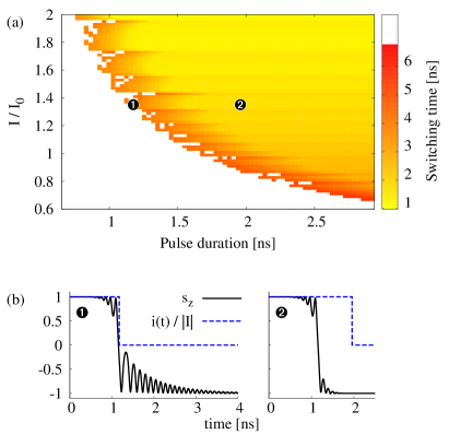
Let us study first the standard spin valve, X=Py(20). The in-plane and out-of-plane components of the STT acting on the Py(8) sensing layer show sine-like angular dependences, see dashed lines in Fig. 1. Switching time as a function of the pulse duration and reduced current density () is shown in Fig. 2(a). Here, we consider zero temperature limit and the external magnetic field is set to zero. Two different regions in the switching diagram can be distinguished. First, the white non-switching region is observed for short current pulses and low current densities. In this region, the energy gain due to STT does not overcome the Gilbert damping and system stays in the initial local magnetic energy minimum. The second region corresponds to successful switching to the AP state. The switching time is shown in the color scale. The decreases nonmonotonously with increasing current density. The most bright area corresponds to the ultra-fast switching, in which the spin reaches the AP configuration before the current pulse ends (). In such a case the switching is realized in a single ultra-fast step after a half precession around the axis; see Fig.2(b) right.
The boundary between non-switching and ultra-fast switching regions develops into a ripple structure. In this region, the energy gain due to spin-transfer leads to a retarded switching, where the switching time , see Fig.2(b) left. The switching for is accompanied with a ringing, where the spin relaxes to the AP state due to energy dissipation via the Gilbert damping only. Such dissipation, however, is rather slow and therefore the retarded switching is much more slower than the ultra-fast single-step switching.
To speed up switching from P to AP state one may consider a negative external magnetic field. On the other hand, a positive magnetic field exceeding the anisotropy field leads to commonly observed steady-state out-of-plane precessional (OPP) modes Myers et al. (1999); Katine et al. (1999); Kiselev et al. (2003), which are the result of the energy balance between Gilbert damping and the energy gain due to spin-transfer.
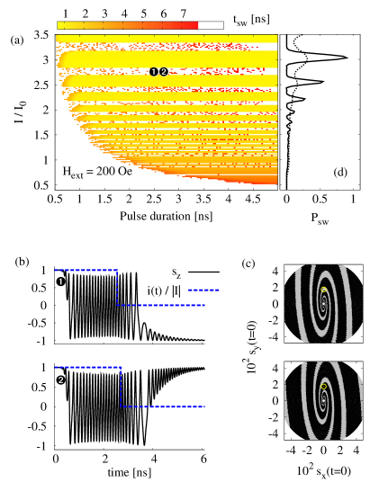
Our analysis shows that for positive external magnetic field, the continuous switching region in the diagram shown in Fig. 2(a) splits into an non-compact current dependent stripe structure. In Fig. 3(a) we show the switching diagram for . The switching regions alternate with the stripes where the spin transfer induces the OPP regime. Since, the current pulse is finite, the final state depends on the actual spin state at the , which falls into the basin of attraction either of P or AP state. This is shown in Fig. 3(b), where two switching events under the current pulses of the same amplitude () and different pulse duration are driven via the OPP regime. We note that in the switching regions the spin dynamics is similar to the zero-field switching discussed above.
To elucidate the stripe structure, we plotted in Fig. 3(c) map of the final spin states as a function of the initial spin position , assuming constant current amplitude and pulse duration . The gray (black) regions correspond to the initial spin position, which results in the final OPP (AP) regime. Comparing the maps calculated for two different current densities ( and ), one concludes that the dynamical phase portrait depends rather strongly on the current density. In other words, current-driven dynamics from the same initial state can develop to different final states. Further increase of external magnetic field leads to shrinking of the PAP switching stripes. For fields much larger than the coercive field the switching stripes disappear so the OPP regime remains only. We note that the initial spin position (close to the P configuration) assumed in this paper (except Fig.3(c)) is denoted in Fig.3(c) by the circles.
The sharp stripe structure is a result of deterministic dynamics and fixed initial condition. When a distribution of initial configurations is taken into account, some smearing of the border between the stripes is observed (not shown). The boundaries are also smeared when non-zero temperature is considered. In Fig. 3(d) we show the switching probabilities as a function of the current pulse density, calculated for pulse duration at and , and for fixed initial configuration. The statistics has been calculated from events for each value of the current density. The switching probability follows the stripe structure in the zero temperature limit, and decreases with decreasing current amplitude. For , the probability is lowered by the factor of about 3 and the peaks broaden. From this follows that smearing of the boundaries between switching and precessional regions increases with increasing temperature. In addition, positions of the peaks are shifted, which reflects the fact that thermal fluctuations act on the spin like an additional torque, and non-linearly influence the spin dynamics.
III.2 Dynamics in a Co/Cu/Py spin valve
The Co(8)/Cu(10)/Py(8) spin valve exhibits non-standard STT acting on the Py(8) layer. Due to the wavy-like dependence of the STT, shown by the solid lines in Fig. 1, positive current stabilizes both the P and AP configurations. A negative current, in turn, destabilizes both the collinear configurations. This characteristic property of the wavy torque raises the question, whether it is possible to switch an asymmetric spin valve between P and AP states without the need of an external magnetic field.
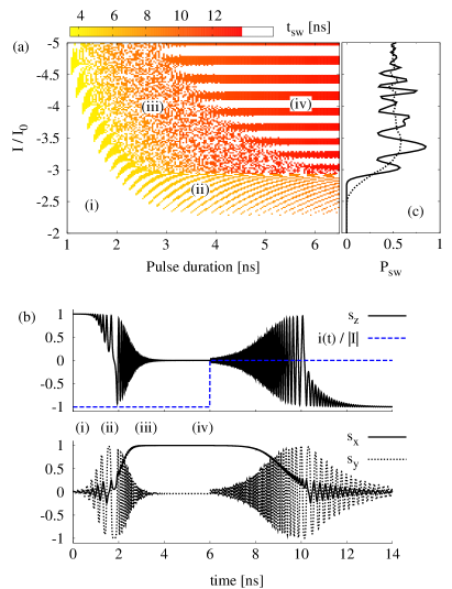
In Fig. 4(a) we show the switching diagram from P to AP state under a rectangular current pulse. Here one may distinguish four characteristic switching regions. First region, denoted by (i), corresponds to low current amplitudes and/or short pulses, where switching does not take place. The non-compact region (ii) of rib-like structure borders the non-switching region and comprises relatively short pulses leading to the fast switching processes. In region (iii) the P/AP bistability of the final states is observed. Finally, in the region (iv) the final state of the dynamics depends on the applied current density, resulting in the band-like structure. The structure contains regions with final P state, which regularly alternate with the regions of final AP state.
In order to explain the complex diagram structure, let us study current-pulse-induced dynamics due to the pulse of amplitude at zero temperature. The temporal dependence of the spin components is shown in Fig. 4(b). When the constant current pulse is applied (in zero external magnetic field), it induces initially small-angle in-plane precessions (IPP) of the sensing layer around the -axis. The precessional angle rapidly increases and spin dynamics turns to the OPP regime, where spin precesses mainly around the demagnetization field. The out-of-plane component of the STT, , assists in the transition to the OPP-like regime Gmitra and Barnaś (2006a). Numerical analysis reveals that the transition depends on the current amplitude, and spin can precess with positive or negative component. Considering constant initial spin direction, OPP direction depends mainly on the current density. This appears because the spin phase portrait, and hence the spin trajectory, are modified due to the current density. Such a situation is similar to that discussed in Fig. 3(c) for the Py/Cu/Py spin valve. Due to the sustained energy pumping to the system via the spin-transfer, the OPP angle decreases and the spin is finally driven into one of the possible static states (SS) close to the (), or (), depending on the sign of the component in the OPP regime. The states are the static fixed points that result from the interplay between the STT and effective magnetic field (mainly its demagnetization part). The points are close to the maximum magnetic energy. Therefore, if current is turned off, the spin position becomes unstable; spin is driven due to Gilbert damping through the OPP regime with decreasing precessional frequency to the IPP regime. In the IPP regime, spin precesses around () direction and is finally damped to the P (AP) state. We have observed that position of the spin in the () results in the final P (AP) state, see Fig. 4(b). Thus the alternation between P and AP states in the region (iv) in the diagram shown in Fig. 4(a), is predominantly controlled by the current since the position of the static state depends on the current density.
To elucidate other regions in the diagram [Fig. 4(a)], we have to consider shorter pulses. According to the diagram, to have a successful switching event, the pulse has to exceed a critical current density and duration. In the static limit () the critical density is about . For a finite pulse duration, higher densities are necessary to drive the spin during the time away from the P state. When the pulse is shorter than a critical one, the relaxation back to the P state takes place [region (i)]. To escape the basin of attraction, the time has to exceed an escape time that depends on the actual magnetic energy and the current density. For the higher current densities, the spin is driven faster away and a shorter escape time is needed. If the pulse ends just before the onset of the OPP regime, the spin is then placed within the basin of attraction of the AP state. The relaxation via the Gilbert dissipation drives the system to the AP state [region (ii)]. If the spin is driven further away from the P state, the IPP regime switches fast to the OPP one. In such a case the final state strongly depends on the precession phase at , i.e., when the current is turned off. This gives rise to the P/AP bistability in the region (iii). The bistable regime appears up to the pulse duration that is not longer than the time necessary for spin stabilization in the state. Note, that this analysis is valid only for current amplitudes . In case of smaller amplitudes, only the steady-state large-angle IPP regime has been observed, and apart from the region (i) only the region (ii) is present. The periodic rib-like structure in the region (ii) arises from the dependence of the final state on the precession phase at time .
When temperature is nonzero, the final state is affected by the thermal noise that modifies the overall spin switching trajectory. In Fig. 4(c) we show switching probability as a function of the current density for , and (solid line) and (dotted line). The switching probability oscillates following the zero-temperature stripe structure, similarly as for the spin valve Py(20)/Cu(10)/Py(8), see Fig. 3(b). However, the probability oscillates now around the value of , and for increased current densities approaches this value for any temperature. We have found that for higher current densities the spin is driven via the OPP-like transient regime much closer to the SS state. This regime is sensitive to the thermal fluctuations mainly due to the component of the thermal field transverse to the spin trajectory. When the spin remains in the transient regime for a longer time, the impact of the thermal fluctuations is larger and leads to equilibration of the probabilities for switching to the P and AP states ().
III.3 Switching in nonstandard spin valves
The fastest switching process in the asymmetric spin valves appears in the region (ii) [see Fig.4(a)]. This region, however, is non-compact and therefore to obtain a successful switching one has to set the current pulse parameters very precisely. In the region (iii) the bistability of the final state makes the switching out of control. Thus, the most convenient for switching seems to be the region (iv). For a proper choice of parameters (pulse duration and current amplitude, including also the thermal effects), corresponding to the maximum of the , see Fig. 4(c), it is possible to obtain controllable switching. However, complex spin dynamics, especially the ringing which appears after the end of current pulse, significantly lengthen the switching time. In practice, the longer the switching time is the more sensitive is the spin evolution to the external disturbances and temperature. Therefore, it is highly desired from the applications point of view to shorten the switching time as much as possible. Accordingly, we propose here a double-pulse switching scheme. The scheme includes two rectangular current pulses of certain amplitudes and durations. The first pulse of negative current, referred to as destabilizing pulse, drives the spin out of its initial position. We note that both the collinear configurations are now unstable. The second pulse of positive current, called stabilizing pulse, controls the dynamics and drives the spin into the final state. Moreover, the stabilizing pulse shortens the switching time (suppressing the ringing) via additional energy dissipation from the system.
In Fig. 5(a) we show time evolution of the component due to single current-pulse and double current-pulse. Here we consider infinitely long stabilizing pulse that in principle has no effect on the spin dynamics for . Due to the first current pulse of density , the STT drives the spin to the SS state. When the first pulse is not followed by the second (stabilizing) one, the spin returns back via the OPP and IPP regimes to the initial state. In the case of double-pulse, however, the stabilizing pulse of drives the spin to the AP state. More systematical study reveals that including the stabilizing current pulse of leads to considerable modification of the switching diagram (not shown). More specifically, the region (ii) becomes wider and switching times under this current pulses falls down from to . Bistability in the region (iii) becomes reduced, but still not completely removed. Finally, in the region (iv) the bands related to switching become enlarged, e.g., at , in the range of amplitudes from to one obtains controllable switching for pulses . Further manipulation of the stabilizing pulse amplitude, indeed, enhances overall controllability of the switching.
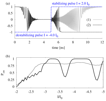
In addition to the enhanced controllability due to the stabilizing pulse, we have observed enhancement of the switching probability at finite temperatures. In Fig. 5(b) we show the switching probability as a function of the current density of destabilizing pulse, that is followed by a stabilization current pulse of and . For and , the probability oscillates with increasing current magnitude, similarly as in the case of a single pulse, see Fig. 4(c). The regions of successful switching are then broadened and the corresponding amplitude is close to unity. In the case of , the switching probability in this region is roughly constant and approaches .
IV Summary and conclusions
We have studied dynamics of the current-pulse induced magnetization switching in both standard and nonstandard spin valves. The calculated switching diagrams reveal the pulse parameters that are suitable for ultra-fast spin switching. We showed that the schemes of optimal switching strongly depend on the type of pillar structure, and are different for standard and nonstandard spin valves. The wavy-like torque in nonstandard spin valves introduces stable points in the phase portrait for negative currents. These stable points are responsible for the P/AP bistability in the pulse switching diagram, which hinders obtaining successful switching. Therefore, we proposed a switching scheme making use of two current pulses, which can efficiently overcome the bistable behavior. Additionally, the application of second, positive, current pulse speeds-up the spin dynamics and fasten the switching process for several times. We have also shown, that the proposed scheme leads to enhanced switching probability even at high temperatures.
The work has been supported by the the EU through the Marie Curie Training network SPINSWITCH (MRTN-CT-2006-035327). M. G. also acknowledges support within research projects MVTS POL/SR/UPJS07 and VEGA 1/0128/08. J. B. also acknowledges support from the Polish Ministry of Science and Higher Education as a research project in years 2006 – 2009 and National Scientific network ARTMAG. P. B. also thanks to E. Jaromirska and L. López-Díaz for helpful discussions.
References
- Slonczewski (1996) J. C. Slonczewski, J. Magn. Magn. Mater. 159, L1 (1996).
- Berger (1996) L. Berger, Phys. Rev. B 54, 9353 (1996).
- Tsoi et al. (1998) M. Tsoi, A. G. M. Jansen, J. Bass, W.-C. Chiang, M. Seck, V. Tsoi, and P. Wyder, 80, 4281 (1998).
- Myers et al. (1999) E. B. Myers, D. C. Ralph, J. A. Katine, R. N. Louie, and R. A. Buhrman, Science 285, 867 (1999).
- Katine et al. (1999) J. A. Katine, F. J. Albert, R. A. Buhrman, E. B. Myers, and D. C. Ralph, Phys. Rev. Lett. 84, 3149 (1999).
- Kiselev et al. (2003) S. I. Kiselev, J. C. Sankey, I. N. Krivorotov, N. C. Emley, R. J. Schoelkopf, R. A. Buhrman, and D. C. Ralph, Nature 425, 380 (2003).
- Serrano-Guisan et al. (2008) S. Serrano-Guisan, K. Rott, G. Reiss, J. Langer, B. Ocker, and H. W. Schumacher, Phys. Rev. Lett. 101, 087201 (2008).
- Garzon et al. (2008) S. Garzon, L. Ye, R. A. Webb, T. M. Crawford, M. Covington, and S. Kaka, Phys. Rev. B 78, 180401 (2008).
- Urazhdin and Button (2008) S. Urazhdin and S. Button, Phys. Rev. B 78, 172403 (2008).
- Barnaś et al. (2005) J. Barnaś, A. Fert, M. Gmitra, I. Weymann, and V. Dugaev, Phys. Rev. B 72, 024426 (2005).
- Valet and Fert (1993) T. Valet and A. Fert, Phys. Rev. B 48, 7099 (1993).
- Urazhdin et al. (2003) S. Urazhdin, N. O. Birge, J. W. P. Pratt, and J. Bass, Phys. Rev. Lett. 91, 146803 (2003).
- Penn and Stiles (2005) D. R. Penn and M. D. Stiles, Phys. Rev. B 72, 212410 (2005).
- Gmitra and Barnaś (2006a) M. Gmitra and J. Barnaś, Phys. Rev. Lett. 96, 207205 (2006a).
- Gmitra and Barnaś (2006b) M. Gmitra and J. Barnaś, Appl. Phys. Lett. 89, 223121 (2006b).
- Gmitra and Barnaś (2007) M. Gmitra and J. Barnaś, Phys. Rev. Lett. 99, 097205 (2007).
- Boulle et al. (2007) O. Boulle, V. Cros, J. Grollier, L. G. Pereira, C. Deranlot, F. Petroff, G. Faini, J. Barnaś, and A. Fert, Nature Phys. 3, 492 (2007).
- Boulle et al. (2008) O. Boulle, V. Cros, J. Grollier, L. G. Pereira, C. Deranlot, F. Petroff, G. Faini, J. Barnaś, and A. Fert, Phys. Rev. B 77, 174403 (2008).
- Acremann et al. (2006) Y. Acremann, J. P. Strachan, V. Chembrolu, S. D. Andrews, T. Tyliszczak, J. A. Katine, M. J. Carey, B. M. Clemens, H. C. Siegmann, and J. Stöhr, Phys. Rev. Lett. 96, 217202 (2006).
- Berkov and Gorn (2005) D. V. Berkov and N. L. Gorn, Phys. Rev. B 72, 094401 (2005).
- Brown (1963) W. F. Brown, Phys. Rev. 130, 1677 (1963).
- Gargía-Palacios and Lázaro (1998) J. L. Gargía-Palacios and F. J. Lázaro, Phys. Rev. B 58, 14937 (1998).
- Kloeden and Platen (1992) P. E. Kloeden and E. Platen, Numerical Solution of Stochastic Differential Equations (Springer-Verlag, 1992).
- Roberts (2000) S. W. Roberts, Technometrics 42, 97 (2000).
- Bauer et al. (2003) G. E. W. Bauer, Y. Tserkovnyak, D. Huertas-Hernando, and A. Brataas, Phys. Rev. B 67, 094421 (2003).
- Gmitra and Barnaś (2009) M. Gmitra and J. Barnaś, Phys. Rev. B 79, 012403 (2009).
- Urazhdin et al. (2005) S. Urazhdin, R. Loloee, and J. W. P. Pratt, Phys. Rev. B 71, 104430 (2005).