Laser Frequency Combs for Astronomical Observations
A direct measurement of the universe’s expansion history could be made by observing in real time the evolution of the cosmological redshift of distant objects. However, this would require measurements of Doppler velocity drifts of 1 centimeter per second per year, and astronomical spectrographs have not yet been calibrated to this tolerance. We demonstrate the first use of a laser frequency comb for wavelength calibration of an astronomical telescope. Even with a simple analysis, absolute calibration is achieved with an equivalent Doppler precision of 9 meter per second at 1.5 micrometers—beyond state-of-the-art accuracy. We show that tracking complex, time-varying systematic effects in the spectrograph and detector system is a particular advantage of laser frequency comb calibration. This technique promises an effective means for modeling and removal of such systematic effects to the accuracy required by future experiments to see direct evidence of the universe’s putative acceleration.
Recent cosmological observations suggest that the universe’s expansion is accelerating. Several lines of evidence corroborate this, including results from distant supernovae (?, ?), the cosmic microwave background (?), and the clustering of matter (?, ?). However, the current observations are all essentially geometric in nature, in that they map out space, its curvature, and its evolution. In contrast, a direct and dynamical determination of the universe’s expansion history is possible by observing the slow drift of cosmological redshifts, , that is inevitable in any evolving universe (?). No particular cosmological model or theory of gravity would be needed to interpret the results of such an experiment. However, the cosmological redshift drift is exceedingly small and difficult to measure; for currently favored models of the universe, with a cosmological constant parametrizing the acceleration, the redshifts of objects drift by less than 1 cm s-1 year-1 (depending on their redshifts).
Nevertheless, the suggestion that the so-called Lyman- ”forest” seen in high-redshift quasar spectra is the best target for this experiment (?) was recently supported by cosmological hydrodynamical simulations (?). The forest of absorption lines is caused by the Lyman- transition arising in neutral hydrogen gas clouds at different redshifts along the quasar sight-lines. Detailed calculations with simulated quasar spectra show that the planned 42-m European Extremely Large Telescope (E-ELT), equipped with the proposed Cosmic Dynamics Experiment (CODEX) spectrograph (?), could detect the redshift drift convincingly with 4000 hrs of observing time over a 20-year period (?). Therefore, as the observation is feasible (in principle), overcoming the many other practical challenges in such a measurement is imperative. Important astrophysical and technical requirements have been considered in detail, and most are not difficult to surmount (?, ?). One (but not the only) extremely important requirement is that the astronomical spectrographs involved must have their wavelength scales calibrated accurately enough to record 1 cm s-1 velocity shifts (25-kHz frequency shifts) in the optical range. Moreover, this accuracy must be repeatable over 20-year timescales.
Although the redshift drift experiment requires demanding precision and repeatability, precisely calibrated astronomical spectrographs have several other important applications. For example, Jupiter- and Neptune-mass extrasolar planets have been discovered by the reflex Doppler motion of their host stars (?, ?, ?), but detecting Earth-mass planets around solar-mass stars will require 5 cm s-1 precision maintained over several-year time scales (?). Another example is the search for shifts in narrow quasar absorption lines caused by cosmological variations in the fundamental constants of nature (?, ?, ?). Recent measurements (?, ?, ?, ?) achieve precisions of 20 m s-1, but the possibility of hidden systematic effects, and the increased photon-collecting power of future ELTs, warrant much more precise and accurate calibration over the widest possible wavelength range.
Laser frequency combs (LFCs) offer a solution because they provide an absolute, repeatable wavelength scale defined by a series of laser modes equally spaced across the spectrum. The train of femtosecond pulses from a mode-locked laser occurs at the pulse repetition rate, , governed by the adjustable laser cavity length. In the frequency domain, this yields a spectrum, , with modes enumerated by an integer to . The carrier envelope offset frequency, , accounts for the laser’s internal dispersion, which causes the group and phase velocities of the pulses to differ (?). Thanks to the large integer , the optical frequencies are at hundreds of THz whereas both and are radio frequencies and can be handled with simple electronics and stabilized by an atomic clock (?). Each mode’s absolute frequency is known to a precision limited only by the accuracy of the clock. Even low-cost, portable atomic clocks provide 1 cm s-1 (or 3 parts in 1011) precision. Because LFC light power is much higher than required, the calibration precision possible is therefore limited by the maximum signal-to-noise ratio (SNR) achievable with the detector. For modern astronomical charge-coupled devices (CCDs), the maximum SNR in a single exposure is limited by their dynamic range but is still sufficient to achieve 1 cm s-1 precision (?). Furthermore, because LFC calibration is absolute, spectra from different epochs, or even different telescopes, can be meaningfully compared.
The main challenge in reaching 1 cm s-1 calibration accuracy will be the measurement and, eventually, mitigation and/or modeling and removal of systematic effects in astronomical spectrographs and detectors. For typical high-resolution spectrographs, a 1 cm s-1 shift corresponds roughly to the physical size of a silicon atom in the CCD substrate. Only with the statistics of a very large number of calibration lines can the required sensitivity be achieved, provided that systematic effects can be controlled accordingly (?). For example, even in a highly stabilized, vacuum-sealed spectrograph, small mechanical drifts will slightly shift the spectrum across the CCD. Although this can easily be tracked to first order, other effects such as CCD intrapixel sensitivity variations will be important for higher precision. Discovering, understanding and eventually modeling and removing these effects is crucial for the long-term goal of accurate calibration; tests of LFCs on astronomical telescopes, spectrographs and detectors are therefore imperative.
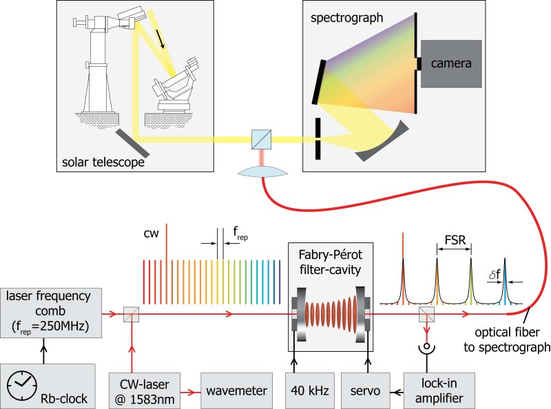
We have conducted an astronomical LFC test on the German Vacuum Tower Telescope (?) (VTT) (Fig. 1). We used a portable rubidium clock with a modest accuracy of 5 parts in (or 1.5 cm s-1); much more accurate clocks are available if needed. This sets the absolute uncertainty on the frequency of any given comb mode. The VTT can be operated at near-infrared wavelengths, thereby allowing a relatively simple and reliable fiber-based LFC to be used. The erbium-doped fiber LFC used had MHz which, despite the VTT spectrograph having higher resolving power (resolution of 0.8 GHz or 1.2 km s-1) than most astronomical spectrographs, is too low for modes to be resolved apart. Filtering out unwanted modes by using a Fabry-Pérot cavity (FPC) outside the laser (?, ?) was suggested as one solution (?, ?) and has proven effective (?, ?). The FPC comprises two mirrors separated by a distance smaller than the laser cavity length so that all modes, except every th (), are interferometrically suppressed (Fig. 1, lower panel). We used a FPC stabilized to a filter ratio, , by controlling its length with an electronic servo system to generate effective mode spacings, , between 1 and 15 GHz. The degree to which the unwanted modes are suppressed is an important parameter: The FPC transmission function falls sharply away from the transmitted mode frequencies but, because nearby suppressed modes are not resolved from the transmitted ones by the spectrograph, small asymmetries in this function (especially combined with time variations) can cause systematic shifts in the measured line positions. With our setup, we achieve an unwanted mode suppression of more than 46 dB at filter ratios . Other possible systematic shifts due to the filtering have been identified (?) and need to be controlled.
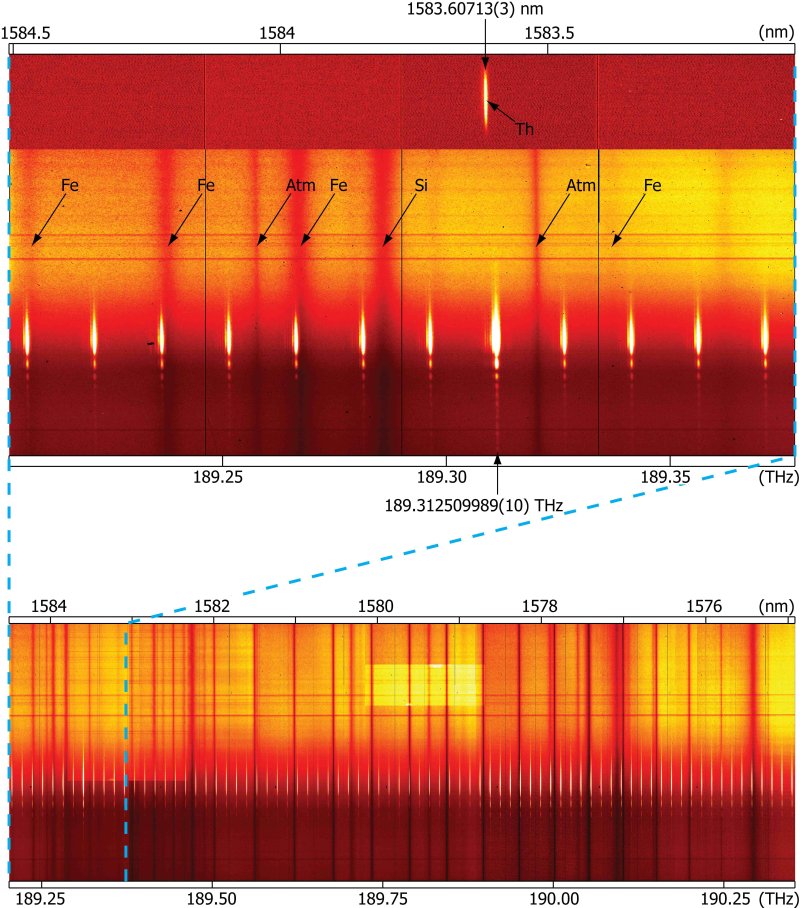
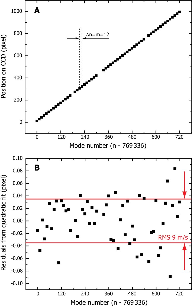
LFC spectra were recorded with and without the spectrum of a small section of the Sun’s photosphere at wavelengths 1.5 m. A sample -GHz recording, superimposed with Fraunhofer and atmospheric lines, is shown in Fig. 2. To estimate our calibration accuracy and to test the spectrograph’s stability, we analyzed several exposures of the LFC only. Individual Lorentzian functions were fitted to the recorded modes as a function of pixel position and identified with the absolute comb frequencies, , which are referenced to the atomic clock (?). The dense grid of modes allows the spectrograph’s calibration function (Fig. 3A) to be determined to very high accuracy; even a simple, second-order polynomial fit to the pixel-versus-frequency distribution has only 9 m s-1 root mean square (RMS) residual deviations around it (Fig. 3B), and this remains almost unchanged with higher-order polynomial modeling (?).
With traditional calibration techniques, such as thorium comparison lamps, I2 gas absorption cells or Earth’s atmospheric absorption lines for calibration achieve 10 m s-1 absolute precision per calibration line at best (?). Thus, even with these ”first light” comb recordings, we already demonstrate superior absolute calibration accuracy. Because more than modes will be available in a larger-bandwidth LFC, the statistical uncertainty would be reduced to the 1 cm s-1 regime if the residuals were truly random. However, the theoretical shot noise limit calculated from the number of photons recorded per comb mode is much smaller than 9 m s-1; systematic effects from the spectrograph and detector system evidently completely dominate the residuals.
The main reason for testing LFCs at real telescopes, on real astronomical spectrograph and detector systems, is to understand how to measure and then mitigate and/or model and remove such systematics. Because the VTT spectrograph is not stabilized (i.e. temperature-, pressure- and vibration-isolated), instrument drifts are expected and the VTT LFC spectra can already be used to track them accurately. From a time series of exposures, we derive a drift in the spectrograph of typically 8 m s-1 min-1 (5 MHz min-1) (?). Much lower drift rates have been demonstrated with suitably stabilized instruments [e.g. 1 m s-1 over months with HARPS (?)]; although the VTT is not optimized for stability, this does not affect its usefulness to test calibration procedures. Indeed, different modes are observed to drift at different rates, with neighboring modes having highly correlated drift rates (?). Also, as the comb modes drift across the detector, higher-order distortions are evident, which are the combined result of many effects, such as intrapixel sensitivity variations. Thus, the VTT data already show an important advantage of LFC calibration: The dense grid of high SNR calibration information allows the discovery and measurement of complex effects correlated across the chip and in time.
The first light for frequency combs on astronomical spectrographs has delivered calibration precision beyond the state of the art. The key opportunity now is to use LFC spectra to measure and remove systematic effects in order to reach the 1 cm s-1 long-term calibration precision, accuracy, and repeatability required to realize the redshift drift experiment.
References and Notes
- 1. A. G. Riess et al., Astron. J. 116, 1009 (1998).
- 2. S. Perlmutter et al., Astrophys. J. 517, 565 (1999).
- 3. D. N. Spergel et al., Astrophys. J. Suppl. 148, 175 (2003).
- 4. J. A. Peacock et al., Nature 410, 169 (2001).
- 5. D. J. Eisenstein et al., Astrophys. J. 633, 560 (2005).
- 6. A. Sandage, Astrophys. J. 136, 319 (1962).
- 7. A. Loeb, Astrophys. J. 499, L111 (1998).
- 8. J. Liske et al., Mon. Not. R. Astron. Soc. 386, 1192 (2008).
- 9. L. Pasquini et al., in Proceedings of the IAU Symposium, P. Whitelock, M. Dennefeld, B. Leibundgut, Eds. (Cambridge Univ. Press, Cambridge, UK, 2006), vol. 232, IAU Symp. Ser., pp. 193–197.
- 10. Materials and methods are available as supporting material on Science Online.
- 11. M. Mayor, D. Queloz, Nature 378, 355 (1995).
- 12. G. W. Marcy, R. P. Butler, Astrophys. J. 464, L147 (1996).
- 13. C. Lovis et al., Nature 441, 305 (2006).
- 14. C. Lovis et al., in Proceedings of the SPIE, I. S. McLean, I. Masanori, Eds. (2006), vol. 6269, pp. 62690P1–9.
- 15. J. N. Bahcall, E. E. Salpeter, Astrophys. J. 142, 1677 (1965).
- 16. J. K. Webb, V. V. Flambaum, C. W. Churchill, M. J. Drinkwater, J. D. Barrow, Phys. Rev. Lett. 82, 884 (1999).
- 17. R. I. Thompson Astron. Lett. 16, 3 (1975).
- 18. M. T. Murphy, J. K. Webb, V. V. Flambaum, Mon. Not. R. Astron. Soc. 345, 609 (2003).
- 19. H. Chand, R. Srianand, P. Petitjean, B. Aracil, Astron. Astrophys. 417, 853 (2004).
- 20. S. A. Levshakov et al., Astron. Astrophys. 449, 879 (2006).
- 21. E. Reinhold et al., Phys. Rev. Lett. 96, 151101 (2006).
- 22. Th. Udem, R. Holzwarth, T. W. Hänsch, Nature 416, 233 (2002).
- 23. M. T. Murphy et al., Mon. Not. R. Astron. Soc. 380, 839 (2007).
- 24. E. H. Schröter, D. Soltau, E. Wiehr, Vistas Astron. 28, 519 (1985).
- 25. T. I. Sizer, IEEE J. Quant. Electron. 25, 97 (1989).
- 26. Th. Udem, J. Reichert, R. Holzwarth, T. W. Hänsch, Phys. Rev. Lett. 82, 3568 (1999).
- 27. P. O. Schmidt, S. Kimeswenger, H. U. Kaeufl, Proc. 2007 ESO Instrument Calibration Workshop, ESO Astrophysics Symposia series (Springer, in press); available at http://arXiv.org/abs/0705.0763.
- 28. C.-H. Li et al., Nature 452, 610 (2008).
- 29. D. A. Braje, M. S. Kirchner, S. Osterman, T. Fortier, S. A. Diddams, Euro. Phys. J. D 48, 57 (2008).
- 30. C. Lovis, F. Pepe, Astron. Astrophys. 468, 1115 (2007).
- 31. We thank the Kiepenheuer Institut für Sonnenphysik staff at the Vacuum Tower Telescope and the Instituto de Astrofisica de Canarias (IAC) personnel for their support during the measurements at the VTT. We especially appreciate the efforts of M. Collados (IAC) and F. Kerber (ESO). We thank T. Kippenberg for CW-laser assistance and J. Liske for advice on the manuscript. M.T.M. thanks the Australian Research Council for a QEII Research Fellowship (DP0877998).
Supporting Online Material
www.sciencemag.org/cgi/content/full/1161030/DC1
Materials and Methods
Figs. S1 to S4
References
28 May 2008; accepted 25 July 2008
SUPPORTING ONLINE MATERIAL
Materials and methods
Laser frequency comb setup
To use frequency combs for precise calibration of astronomical spectrometers, the latter need to resolve apart the modes of the former. Therefore, the comb’s mode spacing must be larger than the spectrometer’s resolution. Most ‘high resolution’ astronomical spectrographs have resolving powers around (where FWHM is the spectrograph’s full-width-at-half-maximum wavelength resolution) to obtain the best signal-to-noise ratio (SNR) for faint, distant astronomical objects. In the infrared region around 1.5 m, the required mode spacing exceeds 2 GHz while the optimum lies around GHz for a typical spectrometer operating in the visible (?).
Unfortunately, a mode-locked laser with GHz corresponds to a laser cavity length of only 1.5 cm. At present, all lasers that reach such a large repetition rate are not useful for calibrating astronomical spectrographs for other reasons: no GHz LFC has yet reached the spectral bandwidth required to provide a large set of lines and to self reference the frequency comb, i.e. to stabilize it to an atomic clock. Current high- LFCs, such as Titanium–Sapphire LFCs, are delicate devices that would not operate autonomously for extended observation times at remote telescopes. The only lasers currently complying with the latter requirement are mode locked fiber lasers. But fiber LFCs with a wide spectral bandwidth have much lower repetition rates than required and so constructing a high- LFC with octave-spanning bandwidth (for self-referencing) is a major technical challenge (?). So far, the highest fundamental pulse repetition rate that has been demonstrated with fiber lasers is 250 MHz (?).
Our approach to solve this problem is to filter the modes with a Fabry-Pérot cavity (FPC) outside the LFC (?, ?, ?, ?, ?). Such an interferometric cavity consists of two mirrors with reflectivity separated by a distance that has a spectral transmission function
| (1) |
This implies a regular grid of transmissions, each wide, with free spectral range . For our purpose the filter mode spacing is set to an integer multiple of the laser comb spacing by adjusting , such that . The filter cavity then transmits exactly every th mode while the unwanted modes in between are largely suppressed.
Our MHz, octave-spanning, erbium-doped fiber LFC was self-referenced with the common – technique (?). A portable rubidium atomic clock with a rather moderate accuracy of 5 parts in was used in this demonstration to stabilize the repetition rate and the carrier envelope offset frequency of the comb. Much better clocks are available if needed. Stabilization of the Fabry-Pérot cavity (FPC) onto the LFC was achieved by modulating the FPC length at 40 kHz using a piezo actuator onto which one of the FPC mirrors is mounted. Part of the transmitted light is sent to a photo-detector whose output is de-modulated with a lock-in amplifier referenced to the modulation frequency. This generates a bi-polar error signal which, using a second piezo actuator, keeps the FPC on resonance. After this locking is achieved, the mode number needs to be identified. This is complicated by the fact that the mode filter cavity can fix onto any comb mode. Thus, a resolution of 250 MHz (i.e. ) is required even though the final effective mode spacing is larger. This is achieved by locking a continuous wave (CW) laser to a comb line while its frequency is measured by a wavemeter. Even though the wavemeter is orders of magnitude less precise than the LFC itself, it is sufficiently accurate (better than 250 MHz) to identify the mode number.
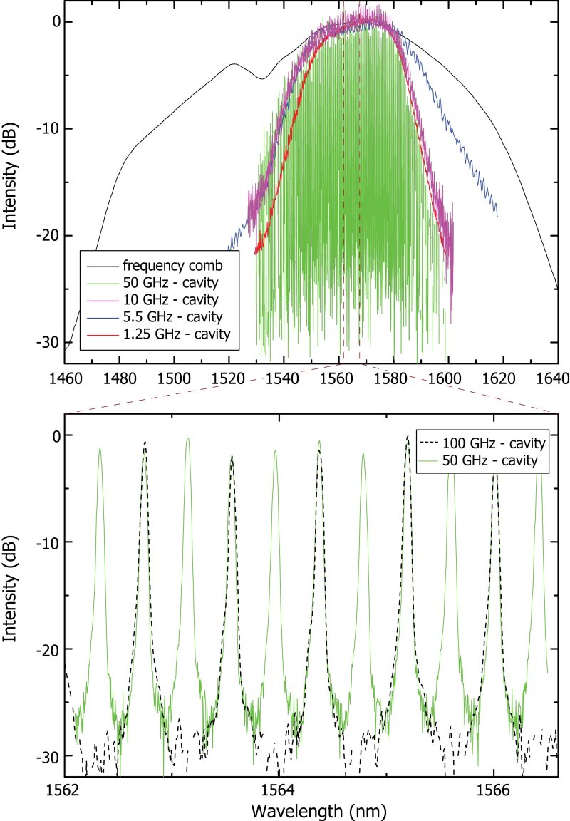
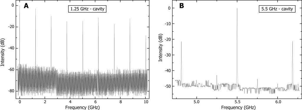
As stated in the main text, it is important to suppress the unwanted modes by a large factor so that they do not contribute to systematic errors in the transmitted mode centroids as measured on the astronomical detector. Fig. S1 shows the spectral envelope of our mode locked laser together with various filter settings, . For large filter ratios the mode spacing can even be resolved with a common laboratory optical spectrum analyzer. Equation S1 states that the laser modes closest to the transmitted mode will have the smallest suppression. For this reason the direct optical spectrum does not provide a good way to estimate the unwanted mode suppression ratio. We used two experimental methods to obtain upper limits on this ratio. Firstly, for direct detection of the unwanted modes in the optical domain, we recorded heterodyne beat signals of the filtered LFC with a CW laser. The unwanted modes are below our detection sensitivity which is 30 dB as shown in Fig. S2 (panel b). Secondly, detecting the pulse repetition rate of the filtered LFC allows to derive the suppression ratio in a rather indirect way. Fig. S2 (panel a) shows the radio frequency spectrum of the filtered pulse train. The filtered mode spacing, , can be understood as being due to the beat frequency between these modes. The component at in the spectrum derives mainly from the beating between the transmitted modes and the suppressed modes closest to them. With everything else ideal the observed mode suppression, as measured in the radio frequency spectrum, appears 6 dB less efficient than for the true optical mode suppression (?).
In future, there might be other useful approaches to reach a sufficient mode spacing aside from using FPCs. Higher repetition rate lasers and fiber lasers maintaining a string (rather than a single) intra-cavity pulse exist, but are currently difficult to employ for astronomical calibration as they produce only a small spectral bandwidth or lack effective methods for suppressing extraneous modes. Another promising technique, albeit in its technological infancy, relies on parametric frequency conversion microresonators (?).
The German Vacuum Tower Telescope
The VTT (?) has a 15 m vertical spectrograph which, with a IR-optimized diffraction grating working in fifth order, provides a very high spectral resolution, . For 1.5 m observations, a TCM8000, 1K1K infrared array from Rockwell Scientific is used as a detector. With an 18.5 m square pixel size it provides a nominal scale of 1.5 nm pixel-1. The spectrograph is pre-dispersed, so only a fraction of one echelle order is recorded simultaneously, covering about 1.5 nm. The filtered LFC light was superimposed with the Sun light by means of a beam splitter cube 1 m in front of the spectrograph’s 40 m entrance slit.
VTT calibration and systematic errors with LFC spectra
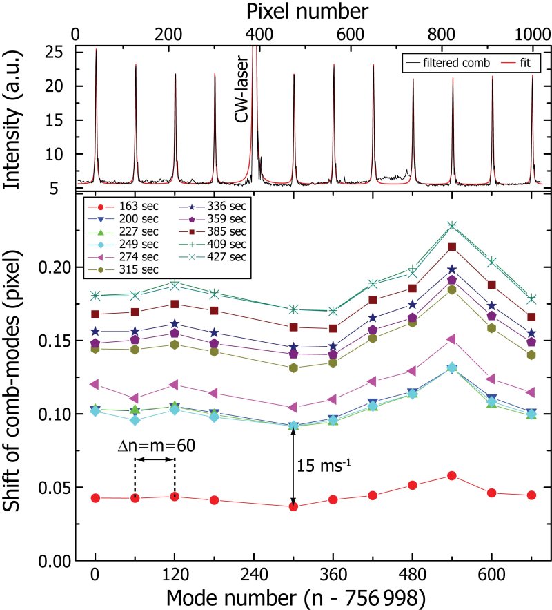
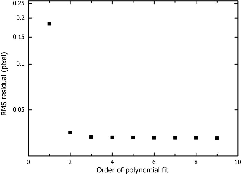
To demonstrate how well the VTT spectrograph’s wavelength scale could be defined using the LFC, we performed a wavelength calibration procedure on a GHz recording similar to that carried out with typical modern astronomical long-slit spectra. The sum of the pixel photon-counts in 100 rows of the detector was used to extract a 1-dimensional comb spectrum. Lorentzian functions (with width 3 pixels) were fitted to the individual comb modes to define their centroids. A similar extraction and fit is shown in the upper panel of Fig. S3 for a GHz recording. Note that the crude extraction technique picks out flaws in the detector and extraneous scattered light; no effort was made to remove these by traditional techniques (e.g. flat-fielding) but obviously spurious data was not included in the multi-Lorentzian fit. Again, for demonstration purposes, this is adequate. The fitted centroids (in pixels) of the comb modes were then plotted against their known frequencies in Hz to form the calibration function of the recording. Polynomial fits of varying order were fitted to the calibration function but it was found that the residuals around the fit reduced only marginally for orders higher than 2 – see Fig. S4. Even around the second order fit, the calibration residuals had a RMS of only 9 m s-1.
As described in the main text, the VTT data are also useful to demonstrate a key advantage of LFC calibration: the mapping out of systematic effects in astronomical spectrographs and detector systems. Since the VTT is not optimized for stability, the largest systematic effect was a small drift of the comb lines across the detector array. The drift was best measured in a series of recordings made with GHz as shown in Fig. S3. Even though the drift was only 0.2 pixels overall, it was easily detected with high precision due to the large amount of calibration information afforded by the LFC modes. Moreover, as can be seen in Fig. S3, there is a distortion in the drift as a function of position along the detector; the drift rate is higher for some parts of the chip. This effect is evident only because it is seen to be correlated among neighboring comb modes. That is, again, the dense calibration information of the LFC allows systematics to be detected.
Of course, with a spectrograph and detector system optimized for stability, the aim would be to largely suppress such effects and precisely measure the residuals. Nevertheless, systematic errors similar to these are still likely to be present at some level larger than 1 cm s-1. For example, inhomogeneities in the spectrograph’s gratings, particularly their rulings, may produce small-scale distortions in the spectrograph’s calibration curve. Intra-pixel sensitivity variations will also be important, as will variations in the pixel size and/or spacing between pixels. By making small adjustments in either and/or in a series of ‘off-line’ calibration exposures (i.e. not taken simultaneously with the science object exposure), a complete and detailed ‘map’ of these effects across the chip can be generated. More difficult to measure and characterize will be time-variations in these distortions. To this end, frequency comb light should be recorded simultaneously with the science object light on the same detector. Of course, the distortions affecting the science spectrum will be very slightly different to those affecting the comb spectrum because of the necessary (but small) spatial separation between them on the detector. These can be corrected to first order using the map above; trend analysis of off-line time-series calibrations should allow higher order corrections.
Comb modes with a finite width are succeptable to yet another systematic effect if correlated frequency and amplitude modulation is present. In this case the spectral center of mass used for calibration could be shifted relative to the average frequency that is referenced to the atomic clolck. Non perfect alignmet of the FPC modes to the comb modes can be the cause of such a correlated modulation as pointed out by D. A. Braje et al. (?). We believe that this effect can be reduced to insignificant levels, for example by narrowing the linewidths of the comb modes.
Still, there may be systematic errors which are difficult to map out (spatially and temporally) with the comb light. For example, one might imagine that some errors occur during the read-out of the detector. It is also likely that some important systematic errors are yet to be discovered or conceived yet. This further illustrates the importance of beginning detailed analyses of frequency comb spectra taken on astronomical detectors in order to test the real precision level achievable before the final designs (and therefore key science activities) of the future generation of telescopes have been determined. Even these first light VTT recordings demonstrate how LFC calibration can be used not only to define the wavelength scale but also as a tool for discovering systematic effects. Only by future, more extensive investigations of this nature can we know whether removing systematics at the 1 cm s-1 precision level is really achievable.
References and Notes
- S1. M. T. Murphy et al., Mon. Not. R. Astron. Soc. 380, 839 (2007).
- S2. T. Wilken, T. W. Hänsch, R. Holzwarth, P. Adel, M. Mei, Quantum Electron. Laser Sci. Conf. (Opt. Soc. America, Washington, DC, U.S.A., 2007), paper CMR3.
- S3. T. I. Sizer, IEEE J. Quant. Electron. 25, 97 (1989).
- S4. Th. Udem, J. Reichert, R. Holzwarth, T. W. Hänsch, Phys. Rev. Lett. 82, 3568 (1999).
- S5. P. O. Schmidt, S. Kimeswenger, H. U. Kaeufl, Proc. 2007 ESO Instrument Calibration Workshop, ESO Astrophysics Symposia series (Springer, in press); available at http://arXiv.org/abs/0705.0763.
- S6. C.-H. Li et al., Nature 452, 610 (2008).
- S7. Th. Udem, R. Holzwarth, T. W. Hänsch, Nature 416, 233 (2002).
- S8. J. Chen et al., Opt. Lett. 33, 959 (2008).
- S9. P. Del’Haye et al., Nature 450, 1214 (2007).
- S10. E. H. Schröter, D. Soltau, E. Wiehr, Vistas Astron. 28, 519 (1985).
- S11. D. A. Braje, M. S. Kirchner, S. Osterman, T. Fortier, S. A. Diddams, Euro. Phys. J. D 48, 57 (2008).