Tunable lateral shift and polarization beam splitting of the transmitted light beam through electro-optic crystals
Abstract
We have investigated the tunable lateral shift and polarization beam splitting of the transmitted light beam through electro-optic crystals, based on the Pockels effect. The positive and negative lateral shifts could be easily controlled by adjusting the permittivity tensor, which is modulated by the external applied electric field. An alternative way to realize the polarization beam splitter was also proposed by the polarization-dependent lateral shifts. Numerical simulations for Gaussian-shaped incident beam have demonstrated the above theoretical results obtained by stationary phase method. All these phenomena have potential applications in optical devices.
pacs:
42.25.Bs; 78.20.Jq; 42.25.Gy; 42.79.FmI INTRODUCTION
It is well known that a light beam totally reflected from an interface between two dielectric media undergoes lateral shift from the position predicted by geometrical optics Goos . This phenomenon was referred to as the Goos-Hänchen (GH) effect Lotsch and was theoretically explained firstly by Artmann in 1948 Artmann . Up till now, the investigations of the GH shifts have been extended to frustrated total internal reflection Ghatak ; Haibel , and attenuated total reflection Yin ; Pillon , and other areas of physics Lotsch , such as quantum mechanics Renard , acoustics Briers , neutron physics Ignatovich , spintronics Chen and atom optics Zhang-WP .
In early 1970s, Reesor et al. Read-1 ; Read-2 found that the lateral shift of a light beam incident on an ordinary dielectric slab is different from the prediction of geometrical optics, when the slab’s thickness is comparable with the wave-length of light. Hsue and Tamir Hsue-T further discussed the lateral shift of a light beam in a transmitting-layer configuration. But they concluded that it is always shifted in a forward direction. Recently, we have predicted theoretically Li and demonstrated experimentally Li-OC that the lateral shift can be negative as well as positive. Historically, the phenomenon of the GH shifts are usually believed to be associated with the evanescent waves in total reflection Goos and frustrated total internal reflection Ghatak ; Haibel . However, the lateral shift discussed here has nothing to do with the evanescent wave. The negative and positive lateral shifts are due to the finite width of the light beam and are different from the prediction of geometric optics. So the lateral shift is similar to but different from GH shift in total reflection, and does result from the reshaping effect of transmitted beam.
Most recently, large (positive and negative) lateral shifts in different slabs containing various materials (such as weakly absorbing media Lai ; Wang-Chen-Zhu , gain media Fan-Wang ; Yan , negative-phase-velocity (NPV) media Berman ; Lakhtakia-1 ; Chen-PRE ; Wang-Zhu and anisotropic metamaterial media Yiang ; Wang-Wang-Zhang ) have attracted much attention, because of their potential applications in integrated optics Lotsch , electromagnetic communication system Li-Vernon , and optical sensors Yin-Hesselink ; Yu . However, it is important for the applications in optical devices to realize the tunability of lateral shift, that is, to control the lateral shift in a fixed configuration or device by external field. Wang et. al. Wang-I-Z once proposed that the lateral shift can be modulated by a coherent control field, which is applied onto the two-level atoms inside a cavity. The modulation of the lateral shift is significant for the further applications in flexible optical-beam steering and optical devices in information processing. Therefore, the main purpose of this paper is to investigate the control of the lateral shift in electro-optic (EO) crystals, based on the Pockels effect Goldstein , which offers opportunity for tuning the optical response characteristics of materials in photonic band-gap engineering Li-ML ; Jim , composite materials Lakhtakia ; Mackay and surface-wave propagation Nelatury , due to the linear change of the refractive indices caused by application of an external electric field.
Our paper is organized as follows. In Sec. II, we derive the lateral shifts of TE and TM polarized light beams in transmission through the EO crystals, according to the stationary phase approach. In Sec. III, we discuss the electric control of the lateral shifts in the case of different crystal cuts. In the same section, an alternative way to realize the polarization beam splitter is also proposed. In Sec. IV, numerical simulations for Gaussian-shaped beam are made to demonstrate the validity of above theoretical results given by stationary phase method. Finally, a conclusion will be given in Sec. V.
II FORMULA
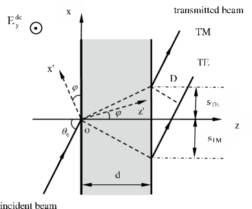
Consider a light beam of angular frequency incident on a slab of EO crystal in the air with an incidence angle specified by the inclination of the beam with respect to the axis, as shown in Fig. 1, where the thickness, relative permittivity and relative permeability
of the nonmagnetic EO crystal slab, are denoted by , , and , respectively. In the case of TE (TM) polarization, the electric (magnetic) field of the plane wave component of the incident beam is assumed to , where , is the wave number in the air, , and are the relative permittivity and permeability of the air, is the speed of light in vacuum, and stands for the incidence angle of the plane wave under consideration. For the sake of simplicity, suppose we have a tetragonal (point group ) uniaxial crystal. The EO crystal with optic axis in the direction has the following index ellipsoid equation:
| (1) |
and the relative permittivity tensor is,
| (5) |
where , , and are the refractive indices for ordinary and extraordinary waves inside the anisotropic slab, respectively. In a electric field along the direction of , the index ellipsoid equation becomes
| (6) |
By making coordinate transformations, as shown in Fig. 1,
| (7) |
the index ellipsoid equation (6) is obtained by
| (8) |
where
and
when the angle is determined by
| (9) |
Moreover, when the optic axis is changed to be in the direction, the index ellipsoid equation and relative permittivity tensor can be expressed by
| (10) |
and
| (14) |
respectively. The index ellipsoid equation in a field along the direction of becomes
| (15) |
Let in the coordinate transformations (7), the above index ellipsoid equation is given by
| (16) |
where , , and . As EO coefficients and are quite different for the tetragonal uniaxial crystals such as ADP and KDP with the others , it clearly makes sense to utilize the two coefficients mentioned above to control the lateral shift, taking account into different crystal cuts. All these expressions obtained here are also valid for the cubic crystal of point group , the symmetry group of such common materials as GaAs, where , .
In order to calculate the lateral shifts, the new relative permittivity tensors in the original frame is expressed as the following form:
| (20) |
where , , . Then, the dispersion equations are given by
| (21) |
and
| (22) |
where for TM polarized wave is also expressed by
| (23) |
where , , . Thus, the field of the corresponding transmitted plane wave is found, according to Maxwell’s equations and the boundary conditions, to be , where the transmission coefficient, , is determined by the following complex number,
| (24) |
and
| (25) |
where . Clearly, the phase shift of the transmitted beam at with respect to the incident beam at is equal to . For a well-collimated TM polarized light beam, the lateral shift is defined as , according to the stationary phase approach Artmann ; Li , and is finally given by
| (26) |
where
| (27) |
, and . It is noted that the subscript in this paper denotes values taken at , namely, . Similarly, the transmission coefficient, , of the TE polarized light beam is determined by the following complex number,
| (28) |
where the phase shift is given by
| (29) |
and . The lateral shift of the TE polarized light beam is defined as , and is given by
| (30) |
where . The lateral shifts of TM and TE polarized light beams presented here depends not only on and , but on , , and . From Eqs. (26) and (30), it is shown that the lateral shifts can be negative when incidence angle is larger than the threshold of angle Li . In what as follows, the properties of the lateral shifts will be discussed in detail. For the tetragonal uniaxial crystals, we have , , and , for ADP and , , and , for KDP at Goldstein , respectively.
III DISCUSSIONS
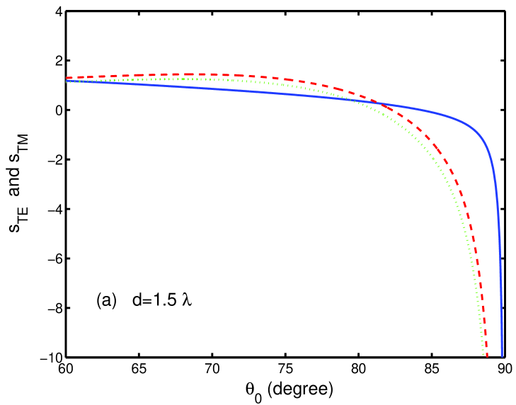
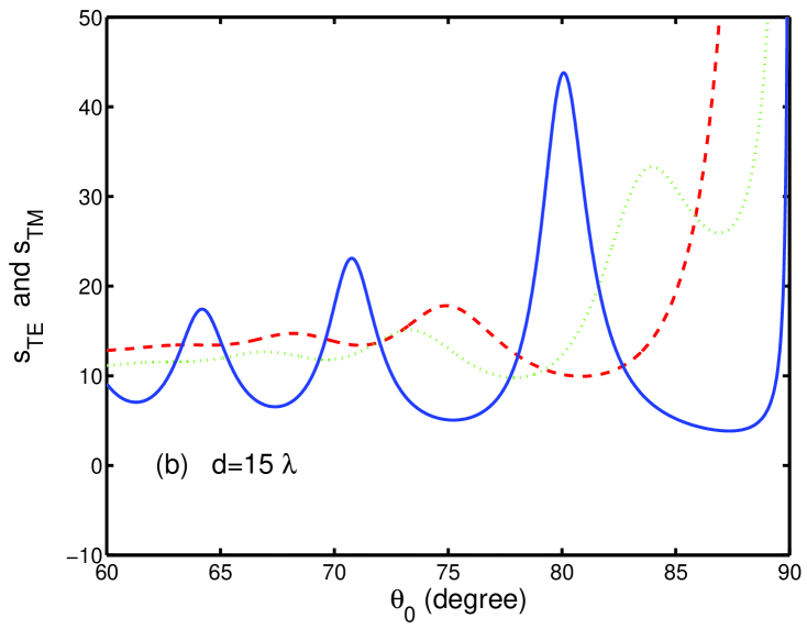
Fig. 2 shows the dependence of the lateral shifts of TM and TE polarized light beams on the incidence angle in the electric-optic crystal with the optic axis in the direction, where (a) and (b) . Solid curve represents the lateral shift of TE polarized beam, dotted and dashed curves represent the lateral shifts of TM polarized beam under the applied electric field and , respectively. It is shown in Fig. 2 that the lateral shift can be negative when the slab’s thickness is small, as mentioned above. The lateral shifts of TM and TE polarized light beams are quite different in the EO crystals with the optical axis in the direction axis. More importantly, the lateral shift of TM polarized beam can be controlled by the applied electric field, while the lateral shift of TE polarized beam in this case is independent of the applied electric field, due to the symmetry of point group considered here.
Now, we will discuss the effect of applied electric field on the lateral shifts. Fig. 3 illustrates that the lateral shifts of TM polarized beam is dependent on the applied electric fields at different incidence angles, where all the physical parameters are the same as in Fig. 2. It is due to the fact that the lateral shift for TM polarized light beam presented here is closely related to , , and , which can be modulated by applied electric field, based on the Pockles effect. As shown in Fig. 3, the lateral shift can be tuned from positive to negative by the applied electric field at larger incidence angle, when the slab’s thickness is small. It is also shown that the electric control of the lateral shift can be realized more easily with the increasing of slab’s thickness. Taking account into that the electrode configuration used for applying an electric field consists of two coplanar electrodes separated by a wide gap Jim , we can easily control the lateral shifts by applied electric field when the EO crystal is subjected to a dc voltage ranging from to (), once one chooses the structure. From a practical point of view, we should point out that the stronger dc field could cause an EO device to malfunction seriously, so that we should find the crystal with large EO coefficients to realize the modulation of the lateral shift by the finite electric field in magnitude.
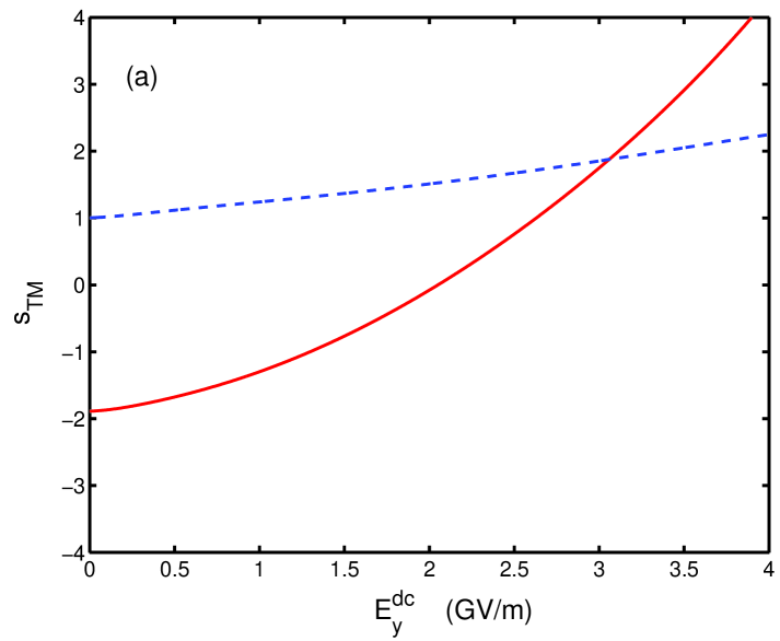
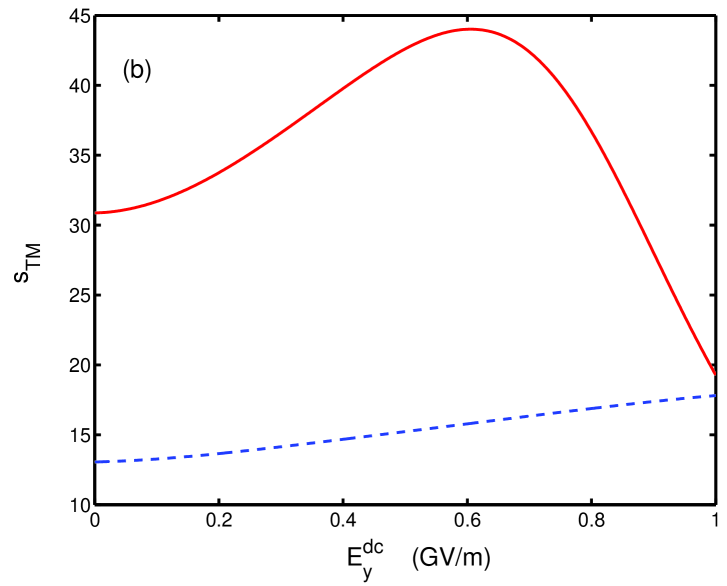
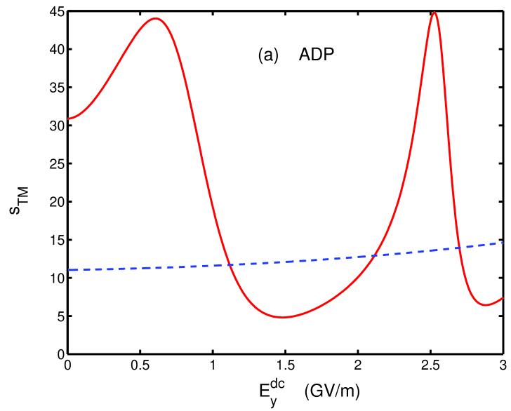
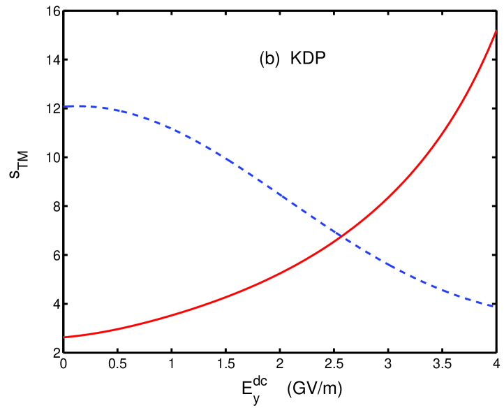
Fig. 4 further shows theoretically the electric control of the lateral shifts in the case of different crystal cuts. Since the modification of the permittivity tensor by the applied electric field is quantified through EO coefficients, not all of which may be independent of each other, depending on the point group symmetry Goldstein , the lateral shifts depend on the different EO coefficients relating to crystal cuts, as shown in Fig. 4, where solid and dashed curves correspond to the -cut and -cut crystals, respectively. By comparison between Fig. 4 (a) and (b), it is thus implied that we can choose the crystal geometry in terms of the relative large EO coefficients used to control the lateral shift efficiently when the electrode is fixed.
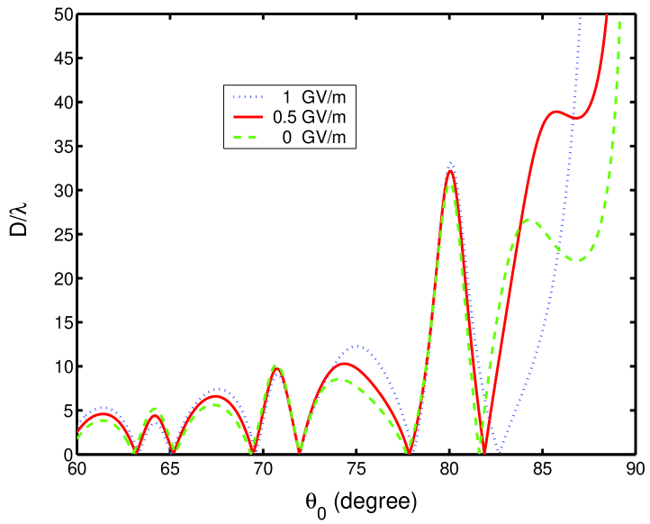
Next, we have a brief look at the polarization beam splitter via tunable lateral shift. In the above discussions, it is clear that the lateral shifts depends on the polarization state of the beam, which leads to the separation of the two orthogonal polarizations of light beam. To illustrate the influence of the applied electric field on polarization beam splitter in EO crystal, we define the distance, as shown in Fig. 1,
| (31) |
which depends on the applied electric field, as shown in Fig. 5. Clearly, the distance can be tuned by the applied electric field. The polarization beam splitting can also be enhanced by external electric field at some large angles, as shown in Fig. 5, where the slab’s thickness is chosen to be . Using this phenomena, the high efficient ultra-compact polarization beam splitter can be achieved by lateral shifts modulated by the applied electric field.
IV NUMERICAL SIMULATIONS
To show the validity of the above stationary-phase analysis, numerical calculations are performed in this section, which confirm our theoretical results. In the numerical simulation, an incident Gaussian-shaped light beam is assumed, , which has the Fourier integral of the following form,
| (32) |
where , is the local waist of beam at , and the amplitude angular-spectrum distribution is Gaussian, . Consequently, when the angular-spectrum distribution is sharply around , the field of the transmitted beam can be written as
| (33) |
If the incident light beam is well collimated, is a sharply distributed Gaussian function around . In this case, the transmission coefficient can be approximated, by writing it in an exponential form, expanding the exponent in Taylor series at and retaining the first two terms, to be
| (34) |
Substituting Eq. (34) into Eq. (33) and and using paraxial approximation, , we finally get the transmitted beam as follow,
| (35) |
where and are determined by,
| (36) |
Obviously, the lateral shift is exactly equal to obtained by stationary phase approach. It is also found that means that the angle deflection of propagation direction depends closely on the width of beam waist, which will disappear when the beam waist is very wide Li ; Li-OC .
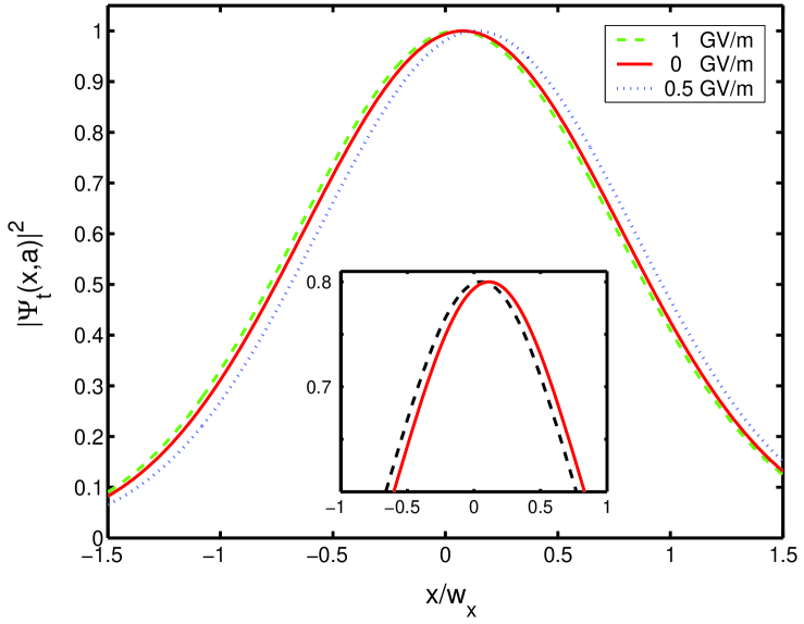
Fig. 6 shows that the normalized Gaussian shapes of the transmitted beam through the EO crystal, where , , , and the other parameters are the same as Fig. 3. It is shown that the lateral shift of TM polarized light beam can be controlled by different applied electric fields. The comparison of the normalized Gaussian shapes of the transmitted TE and TM polarized beams has also shown the polarization beam splitting in the case of , as shown by inset in Fig. 6. Therefore, numerical simulations for a Gaussian-shaped incident beam have demonstrated the validity of the stationary phase method. The numerical results are in good agreement with the above theoretical results when the incident beam is well-collimated, that is, the beam waist of incident beam is wide. The discrepancy between theoretical and numerical results is due to the distortion of the transmitted light beam, especially when the beam waist is narrow.
V CONCLUSIONS
In summary, we have investigated the tunable lateral shifts and polarization beam splitter based on the Pockels effect in cubic and tetragonal EO crystals. It is found that the large positive and negative lateral shifts of TM polarized beam can be controlled by adjusting the permittivity tensor, which is modulated by external electric field. It is also shown that the modulation of the lateral shifts is also closely related to the crystal cuts. Numerical simulations for Gaussian-shaped light beams are made to demonstrate the validity of stationary phase approach. Since the EO coefficient of crystal depends on its symmetry of point group, the lateral shifts of TE and TM polarized beams can be easily controlled in orthorhombic crystals of point group , such as potassium niobate with large EO coefficients and Lakhtakia . In a word, we propose theoretically a useful scheme to control the lateral shifts in EO crystal via the applied electric field. We believe that these phenomena will lead to an alternative way to realize polarization beam splitter, which is essential optical components in optical systems and plays an important role in optical communication, optical recording and integrated optical circuits.
Acknowledgements
X. Chen is grateful to Prof. A. Lakhtakia for providing useful information and helpful suggestions. This work was supported in part by the National Natural Science Foundation of China (60806041, 60877055, and 60806002) and the Shanghai Leading Academic Discipline Program (T0104). X. Chen is also supported in part by Shanghai Educational Development Foundation (2007CG52) and Shanghai Rising-Star Program (08QA14030).
References
- (1) F. Goos and H. Hänchen, Ann. Phys. 1, 333 (1947); 5, 251 (1949).
- (2) H. K. V. Lotsch, Optik (Stuttgart) 32, 116 (1970); 32, 189 (1970); 32, 299 (1971); 32, 553 (1971).
- (3) K. V. Artmann, Ann. Phys. (Leipzig) 2, 87 (1948).
- (4) A. K. Ghatak, M. R. Shenoy, I. C. Goyal, and K. Thyagarajan, Opt. Commun. 56, 313 (1986).
- (5) A. Haibel, G. Nimtz, and A. A. Stahlhofen, Phys. Rev. E 63, 047601 (2001).
- (6) X. Yin, L. Hesselink, Z. Liu, N. Fang, and X. Zhang, Appl. Phys. Lett. 85, 372 (2004).
- (7) F. Pillon, H. Gilles, S. Girard, M. Laroche, R. Kaiser, and A. Gazibegovic, J. Opt. Soc. Am. B 22, 1290 (2005).
- (8) R.-H. Renard, J. Opt. Soc. Am. 54, 1190 (1964).
- (9) R. Briers, O. Leroy, and G. Shkerdinb, J. Acoust. Soc. Am. 108, 1624 (2000).
- (10) V.K. Ignatovich, Phys. Lett. A 322, 36 (2004).
- (11) X. Chen, C.-F. Li, and Y. Ban, Phys. Rev. B 77, 073307 (2008).
- (12) J.-H. Huang, Z.-L. Duan, H.-Y. Ling, and W.-P. Zhang, Phys. Rev. A 77, 063608 (2008).
- (13) L. A. A. Read, Man Wong, and G. E. Reesor, J. Opt. Soc. Am. 68, 319 (1978).
- (14) L. A. A. Read and G.E. Reesor, Can. J. Phys. 57, 1409 (1979).
- (15) C. W. Hsue and T. Tamir, J. Opt. Soc. Am. A 2, 978 (1985).
- (16) C.-F. Li, Phys. Rev. Lett. 91, 133903 (2003).
- (17) C.-F. Li, Q.-B. Zhu, G. Nimtz, X. Chen, and Y. Zhang, Opt. Commun. 259, 470 (2006).
- (18) H. M. Lai, Opt. Lett. 27, 680 (2002).
- (19) L.-G. Wang, H. Chen, S.-Y. Zhu. Opt. Lett. 30, 2936 (2005).
- (20) J. Fan, A. Dogariu, L. J. Wang, Opt. Express 11, 299 (2003).
- (21) Y. Yan, X. Chen and C.-F. Li, Phys. Lett. A 361, 178 (2007).
- (22) P. R. Berman, Phys. Rev. E 66, 067603 (2002).
- (23) A. Lakhtakia, Int. J. Electron. Commun. 58, 229 (2004).
- (24) X. Chen and C.-F. Li, Phys. Rev. E 69, 066617 (2004).
- (25) L.-G.Wang and S.-Y. Zhu, J. Appl. Phys. 98, 043522 (2005).
- (26) Y. Xiang, X. Dai, S. Wen, Appl. Phys. A 87, 285 (2007).
- (27) Z.-P. Wang, C. Wang, Z.-H. Zhang, Opt. Commun. 281, 3019 (2008).
- (28) Q.-M. Li and R.J. Vernon, IEEE Trans. Antennas Propag. 54, 3449 (2006)
- (29) X. B. Yin, L. Hesselink, Appl. Phys. Lett. 89, 261108, (2006).
- (30) T. Y. Yu, H. G. Li, Z. Q, Cao, Y. Wang, Q. S. Shen, Y. He, Opt. Lett. 33, 1001 (2008).
- (31) L.-G. Wang, M. Ikram, and M. S. Zubairy, Phys. Rev. A 77, 023811 (2008).
- (32) D. Goldstein, Polarized light: Second Edition, Revised and Expanded, (Marcel Dekkerr, New York, 2003), P467.
- (33) J. Li, M.-H. Lu, L. Feng, X.-P. Liu, and Y.-F. Chen, J. Appl. Phys. 101, 013516 (2007).
- (34) K. L. Jim, D. Y. Wang, C. W. Leung, C. L. Choy, and H. L. W. Chan, J. Appl. Phys. 103, 083107 (2008).
- (35) A. Lakhtakia and T. G. Mackay, Proc. R. Soc. Lond. A 463, 583 (2007).
- (36) T. G. Mackay, and A. Lakhtakia, J. Appl. Phys. 101, 083523 (2007).
- (37) S. R. Nelatury, J. A. Polo JR., and A. Lakhtakia, Electromagnetics, 28, 162 (2008).