Effects of Bending on Raman-active Vibration Modes of Carbon Nanotubes
Abstract
We investigate vibration modes and their Raman activity of single-walled carbon nanotubes that are bent within their intrinsic elastic limits. By implementing novel boundary conditions for density-functional based tight-binding, and using non-resonant bond polarization theory, we discover that Raman activity can be induced by bending. Depending on the degree of bending, high-energy Raman peaks change their positions and intensities significantly. These effects can be explained by migration of nodes and antinodes along tube circumference. We discuss the challenge of associating the predicted spectral changes with experimental observations.
pacs:
78.30.Na,63.22.-m,63.20.D-,62.25.-gTechnological applications of carbon nanotubes (CNTs) are based on their exceptional mechanical and electronic properties. Due to advances in fabrication and manipulation, CNTs have become one of the most prominent building blocks for nanoscale materials design. Their electronic and mechanical properties can be used in numerous applications for nanoelectronics, hydrogen and energy storage material, sensors, or high-strength composites.Baughman et al. (2002)
Among mechanical propertiesQian et al. (2002), vibrations are relevant in heat dissipationKuroda et al. (2005), sensorsKong et al. (2000) and nanotube identificationJorio et al. (2005). Due to the large number of applications, vibrations have been investigated extensively. In particular, most experimental studies use Raman spectroscopyDresselhaus et al. (2005), a method that is able to achieve even single nanotube resolution.Hartschuh et al. (2003)
In practice, because CNTs are long, they bend. Bending is observed in isolated CNTs between electrodesChang et al. (2007), or in “paper”Barisci et al. (2000), “forests”Ren et al. (1998), ringsSong et al. (2008), and composite systemsLoos et al. (2005) made out of CNTs. It appears that bending is ubiquitous in experiments—and challenging to study theoretically. Most previous theoretical Raman studies are for straight tubes, because modeling of bent systems has been computationally too expensiveDresselhaus et al. (2005). Modeling of bending with classical methods is straightforward, but has been used to study force moments and strainsWu et al. (2007), bucklingGuo et al. (2007); Maiti (2000) and other large-scale mechanical properties that result from rather high curvature.Qian et al. (2002)
In this work we investigate how vibrations and Raman spectra are affected when CNTs are bent slightly, within their intrinsic elastic limits. To accomplish this, novel boundary conditions are introduced which allow quantum mechanical modeling of bending with computationally feasible system size. We show that vibrations undergo systematic changes that significantly alter the high-frequency Raman spectra. The spectral changes can be understood via simple physical principles.
We use density-functional based tight-binding (DFTB) methodFrauenheim et al. (2002) to calculate forces, optimize systemsBitzek et al. (2006), and calculate vibrational eigenmodes. The method has been used successfully for vibrational analysis of carbon nanotubes, also related to Raman activity.Jiang et al. (2005, 2007) Raman spectra are calculated by non-resonant bond polarization methodGuha et al. (1996); Saito et al. (1998). This method has some restrictions and limits direct comparison between resonant experimentsSaito et al. (2001); Marinopoulos et al. (2003), but suffices for the scope of this paper. The details of our approach are given in Ref. Malola et al., 2008.
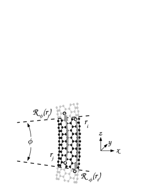
To model bent nanotubes quantum mechanically, we introduce novel “periodic wedge boundary conditions” where the CNT appears as a slice of a torus, as shown in Fig. 1. Some complications arise from fixed quantization axis and require mild approximations.wed Henceforth all directions refer to the fixed Cartesian coordinates shown in Fig. 1.

We stress that in our calculations the bending of CNTs is only due to boundary conditions. All atoms are free to move in the unit cell; no constraints are applied (those would cause severe artifacts for the vibration modes). Note that the length of the tube is automatically optimized since the atoms can freely move in the radial direction of the unit cell.
The single-walled CNTs we investigate are: semiconducting (13,0) tube with Å diameter and Å length, metallic (6,6) tube with Å diameter and Å length, and metallic (13,4) tube with Å diameter and Å length. To have a common measure for the degree of bending for tubes with different chiralities and diameters, we define a dimensionless variable
where is tube’s diameter and the radius of curvature measured from tube axis. Hence (100 %) corresponds to maximum bending (torus with a vanishing hole); buckling of a nanotube takes place above Guo et al. (2007); Maiti (2000) and the range for bendings in experiments is estimated Loos et al. (2005); Chang et al. (2007), which is the range under our focus.
Our main results are embedded in Fig. 2, showing Raman spectra of high-energy modes by systematically varying . Low-energy modes are not shown because they are insensitive to bending, with respect to both energy and intensity. For example, the radial breathing mode is left nearly intact because bending mostly affects bonds parallel to tube axis. On the contrary, within G-band -related high-energy modes bending induces systematic changes: (i) emergence of new peaks, (ii) intensity reductions of “original” (straight-tube) peaks, (iii) significant energy shifts and (iv) splitting of peaks into smaller ones. In (13,0) tube mode even deactivates for moderate bending. The rich spectra of chiral (13,4) tube is further enriched while bent, but still shows similar systematics to achiral tubes.
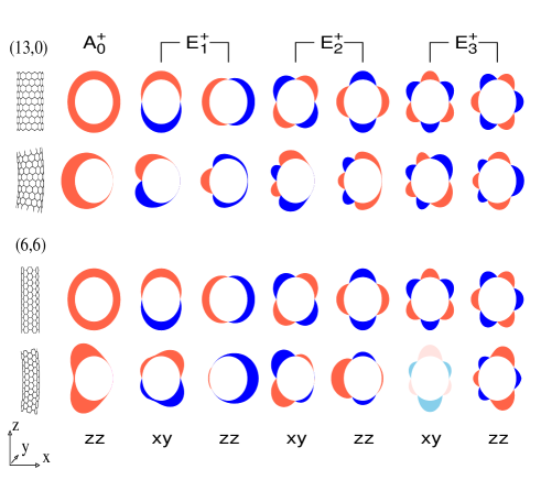
We begin analyzing these results by looking at what happens in the spatial structure of the vibration modes as tubes are bent. To visualize this, we show a qualitative view of the nodes and antinodes for selected modes in Fig. 3. Two-dimensional modes within the same polarization picture are similar and uniform in the direction of the tube, differing only in the number of nodes along tube circumference. In xy and zz polarizations the amplitudes are in (13,0) tube along tube axis and in (6,6) tube along tube circumference (for xz vice versa). As the tube is bent, the nodal structure starts migrating towards the outer or inner side of the torus. Amplitudes are also affected, but the modes remain uniform along tube axis and the transition is smooth. In other words, modes in slightly bent tubes can be always identified with the symmetric modes in straight tubes.
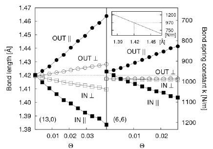
A qualitative change for bent tubes, as shown in Fig. 4 as a function of , is the change in bond lengths and bond stiffnessess. The bonds in inner parts shorten, bonds in outer parts lengthen, with up to % variation for %. Because carbon bonds in honeycomb structure are stiff, the result shows a surprisingly strong ( %) variation in the effective (nearest neighbor) spring constants between the inner and outer parts of the tube.
These observations help us to understand the energy shifts, remembering that . Let us take the -polarization spectrum of (6,6) tube in Fig. 2 as an example. The energies of original and symmetry modes increase; it is because the antinodes concentrate in the inner part of the torus where the spring constants are larger (see Fig. 3). The energies of vibrations originating from and symmetry modes decrease; it is because the antinodes concentrate in the outer part of the torus where the spring constants are smaller (see Fig. 3). Furthermore, looking at Fig. 3 one can realize that the energy of mode decreases more than because the antinodes of concentrate in outer part more strongly. This is part of a more general trend observable in Fig. 3: modes with many circumferential nodes are less affected because antinodes are more equally distributed as tubes are bent. The same observations apply to other spectra. Note that in Fig. 3 bending modifies two-dimensional modes pairwise the same way (antinodes migrate in same direction), and bending does not lift the degeneracy of the modes because energy is for both modes either increased or decreased. Hence the appearance of peak splittings in Fig. 2 is due to originally different modes, not due to lifted degeneracy.
Why does bending cause migration of nodes and antinodes along the circumference? Consider a simple model: calculate the eigenmodes of a simple, one-dimensional ring of atoms connected by harmonic springs, where spring constants are modulated such that on one side of the ring they are larger, on the other side smaller. For this modified system the symmetric eigenmodes change so that nodes and antinodes concentrate either on the region of strong bonds, or on the region of weak bonds, depending on the mode in question. In nanotubes the modes and amplitudes are three-dimensional, but the basic mechanism remains the same.
Finally, let us investigate the induced Raman activity of Fig. 2. Consider for example the mode of (6,6) tube in Fig. 3 that is originally Raman inactive with xy and zz polarizations. Bending breaks the symmetry in -direction and causes mode to resemble and modes—modes that are Raman active for straight tubes. Due to this resemblance and get nearly equal Raman intensitiesMalola et al. (2008). More generally, from -antisymmetric modes, that can be excited by -polarized light but that have broken -symmetry, some will “leak” the polarization into -direction, making the mode active with polarization (e.g. left-hand ’s for (6,6) tube in Fig. 3). Further, from -symmetric modes, that have broken -symmetry, some become active in polarization (e.g. right-hand ’s for (6,6) tube in Fig. 3). For (13,4) tube similar principles apply, but corresponding analysis is somewhat more complicated due to the chirality of the tube.
The arguments above are biased towards the non-resonant bond polarizability model, but we stress that most arguments are related to vibrational eigenmodes (peak positions, node migration), and are independent of the method to calculate the Raman intensities. Therefore most observations should be consistent with more complete theories.
In fact, even the most complete theory would have problems with experimental interpretation. Spectra are calculated only for a piece of potentially complex curved CNT system. We confirmed that the tiny -component, that tube axis has near boundaries, is not the origin for Raman activity “leakage” between polarization pictures. But if nanotube slice is a part of more complete torus, situation becomes more complicated and direct comparison less sensible, because tube axis mixes with other directions. Because the situation depends crucially on the experimental setups, we cannot make here general interpretations.
There have been few experiments aiming for direct observation of Raman spectra for bent nanotubesSong et al. (2008); Ko et al. (2004). In Ref. Ko et al., 2004 the band peak was observed to broaden and shift lower in energy, which was attributed to the increased bond lengths in bent tubes. Because for ideally bent tubes some modes should also decrease in energy, it is likely that in this experiment the tubes were not only bent but also stretched; shift is due to stretching and broadening due to bending. Our highest bending limit, %, was derived from microscopic imagesLoos et al. (2005), but high density of such bendings must involve defects. It is because a bent tube must be anchored via mechanical or chemical bonds; a rough estimate for the bending energy of a tube with any chirality is (eV/atom), which for % bending requires significant eV of anchoring energy per atoms in the tube. Therefore defect-free extreme bending should occur only in singular parts of compound structures, and the Raman intensity from these parts is expected to remain comparably small. On the other hand, Raman measurements for single CNTs could show these effects visibly, especially under experimentally feasible controlled bendingChang et al. (2007).
To conclude, this work provides understanding into effects that bending causes for vibrational spectra of CNTs. The effects are significant, but can be systematically explained with general principles, which should be valid for multi-walled nanotubes or even for non-carbon nanotubes.
This research is supported by the Academy of Finland through projects 121701 and 117997, the FINNANO consortium MEP (molecular electronics and nanoscale photonics), and by the Finnish Cultural Foundation (SM). We thank M. Pettersson and M. Manninen for fruitful discussions. The computations were done in the NanoScience Center (NSC), University of Jyväskylä.
References
- Baughman et al. (2002) R. H. Baughman, A. A. Zakhidov, and W. A. de Heer, Science 297, 787 (2002).
- Qian et al. (2002) D. Qian et al., Appl. Mech. Rev. 55, 495 (2002).
- Kuroda et al. (2005) M. A. Kuroda, A. Cangellaris, and J.-P. Leburton, Phys. Rev. Lett. 95, 266803 (2005).
- Kong et al. (2000) J. Kong et al., Science 287, 622 (2000).
- Jorio et al. (2005) A. Jorio et al., Phys. Rev. B 71, 075401 (2005).
- Dresselhaus et al. (2005) M. S. Dresselhaus et al., Physics Report 409, 47 (2005).
- Hartschuh et al. (2003) A. Hartschuh et al., Science 301, 1354 (2003).
- Chang et al. (2007) C. W. Chang et al., Phys. Rev. Lett. 99, 045901 (2007).
- Barisci et al. (2000) J. N. Barisci, G. G. Wallace, and R. H. Baughman, Journal of Electroanalytical Chemistry 488, 92 (2000).
- Ren et al. (1998) Z. F. Ren et al., Science 282, 1105 (1998).
- Song et al. (2008) L. Song et al., Appl. Phys. Lett. 92, 121905 (2008).
- Loos et al. (2005) J. Loos et al., Ultramicroscopy 104, 160 (2005).
- Wu et al. (2007) J. Wu, K. C. Hwang, and Y. Huang, Journal of Mechanics and Physics of Solids 56, 279 (2007).
- Guo et al. (2007) X. Guo et al., Composites: Part B 39, 202 (2007).
- Maiti (2000) A. Maiti, Chem. Phys. Lett. 331, 21 (2000).
- Frauenheim et al. (2002) T. Frauenheim et al., J. Phys.: Condens. Matter 14, 3015 (2002).
- Bitzek et al. (2006) E. Bitzek et al., Phys. Rev. Lett. 97, 170201 (2006).
- Jiang et al. (2005) J. Jiang et al., Phys. Rev. B 72, 235408 (2005).
- Jiang et al. (2007) J. Jiang et al., Phys. Rev. B 75, 035407 (2007).
- Guha et al. (1996) S. Guha et al., Phys. Rev. B 53, 13106 (1996).
- Saito et al. (1998) R. Saito et al., Phys. Rev. B 57, 4145 (1998).
- Saito et al. (2001) R. Saito et al., Phys. Rev. B 64, 085312 (2001).
- Marinopoulos et al. (2003) A. G. Marinopoulos et al., Phys. Rev. Lett. 91, 046402 (2003).
- Malola et al. (2008) S. Malola, H. Häkkinen, and P. Koskinen, Phys. Rev. B 77, 155412 (2008).
- (25) Fixed quantization axis complicates matrix element calculation for some orbital pairs that cross a boundary. This requires averaged matrix elements and forces between boundaries. By using long tubes, small ’s, and avoiding atoms too near wedge apex, these approximations are valid.
- Barros et al. (2006) E. B. Barros et al., Phys. Rep. 431, 261 (2006).
- Riter (1970) J. R. Riter, The Journal of Chemical Physics 52, 5008 (1970).
- Schelling and Keblinski (2003) P. K. Schelling and P. Keblinski, Phys. Rev. B 68, 035425 (2003).
- Ko et al. (2004) H. Ko et al., Appl. Phys. Lett. 85, 2598 (2004).