Also at ]Department of Radiophysics, Taras Shevchenko National University of Kiev, Kiev, Ukraine.
Parametrically-stimulated recovery of a microwave signal using standing spin-wave modes of a magnetic film
Abstract
The phenomenon of storage and parametrically-stimulated recovery of a microwave signal in a ferrite film has been studied both experimentally and theoretically. The microwave signal is stored in the form of standing spin-wave modes existing in the film due to its finite thickness. Signal recovery is performed by means of frequency-selective amplification of one of these standing modes by double-frequency parametric pumping process. The time of recovery, as well as the duration and magnitude of the recovered signal, depend on the timing and amplitudes of both the input and pumping pulses. A mean-field theory of the recovery process based on the competitive interaction of the signal-induced standing spin-wave mode and thermal magnons with the parametric pumping field is developed and compared to the experimental data.
pacs:
75.30.Ds, 76.50.+g, 85.70.GeI Introduction
The problem of microwave information storage and processing using elementary excitations of matter has been intensively studied both theoretically and experimentally. For a long time the search concentrated on different types of echo-based phenomena involving phase conjugation techniques Echo_Review ; WFR_1 .
Several years ago, a new method of signal restoration was proposed and tested in the experiments with dipolar spin waves scattered on random impurities and defects of a ferrimagnetic medium Reversal_of_Momentum_Relaxation . In the framework of this method, to achieve the signal restoration, a frequency-selective parametric amplification of a narrow band of scattered spin waves (having frequencies close to the frequency of the input signal) was used. As a result of this selective amplification, a uniform distribution of the secondary (scattered) spin waves in the phase space of the system was distorted, and a macroscopic noise-like signal was registered at the output Methods_of_relaxation_reversal . The noise-like character of the restored signal is caused by the fact that this signal is formed by many individual scattered spin waves, having close, but arbitrarily shifted phases.

Recently PRL_restoration , we have reported experimental results on storage and recovery of a microwave signal using a single standing spin-wave mode belonging to the discrete spin-wave spectrum, which is caused by the spatial confinement of the magnon gas in a thin yttrium-iron-garnet (YIG) ferrite film. The storage effect was realized through the conversion of the input microwave signal into a propagating magnetostatic wave (or dipolar spin wave), and, then, into an exchange-dominated standing spin-wave modes (or thickness modes) of the film. The recovery of the signal was performed by means of frequency-selective parametric amplification, but, in contrast with Reversal_of_Momentum_Relaxation , the restored signal was formed by a single standing spin-wave mode of the film, and had a practically noiseless character. The mechanism of such a restoration is highly non-trivial. Therefore, in our first report PRL_restoration we used an approximate empirical theoretical model to explain this rather complicated restoration process.
In our present paper we give a detailed theoretical explanation of the restoration effect. This explanation is based on the general theory of parametric interaction of spin waves (so-called “S-theory”) S-theory_Lvov_book and takes into account interactions between different groups of spin waves existing in a ferrite film. Using the developed theory we calculate parameters of the restored pulse (power, duration, and delay in respect to the input pulse) as functions of the power of the input and pumping pulses, and compared these calculated parameters with experimental data.
II Experiment
For the reason of completeness we report here again the experimental findings presented in PRL_restoration , amended by additional experimental investigations. The experimental setup is shown in Fig. 1. The input electromagnetic microwave pulse is converted by the input microstrip transducer into dipolar spin waves, that propagate in a long and narrow ( mm2), 5 m thick yttrium iron garnet (YIG) film waveguide (saturation magnetization G, exchange constant Oecm2). The other transducer, used to receive the output microwave signals, is placed at a distance of mm from the input one. A bias magnetic field of Oe is applied in the plane of the YIG film waveguide, along its width and perpendicular to the direction of the spin wave propagation.
The input rectangular electromagnetic pulses having a duration of 100 ns, carrier frequency of GHz, and varying power of 0.1 mW were supplied to the input transducer. These input pulses excite wave packets of magnetostatic surface waves (MSSW) (or Damon-Eshbach magnetostatic waves Magnetostatic_Modes_of_Ferromagnetic_Slab ), having a carrier wave number cm-1. The group velocity of the excited wave packet is about 2.3 cms. This group velocity determines the time delay of the propagating wave packet between the input and output transducers of about 350 ns. The spin-wave packet received by the output transducer is, again, converted into an electromagnetic pulse. After amplification and detection, the output signal is observed with an oscilloscope.
As it was pointed out in PRL_restoration , the propagating MSSW excited in the ferrite film standing (thickness) spin-wave modes that continued to exist in the film long after the propagating MSSW signal reach the output transducer. To recover the microwave signal stored in these standing spin-wave modes it is necessary to apply to the film an external pumping microwave field with the frequency that is approximately two times larger than the carrier frequency of the stored microwave signal. To supply this double-frequency pumping pulse an open dielectric resonator is placed in the middle of the YIG waveguide. The resonator is excited by an external microwave source and produces a pumping magnetic field that is parallel to the static bias magnetic field , see Fig. 1. The resonance frequency of the pumping dielectric resonator GHz was chosen to be close to twice the carrier frequency of the input microwave pulse. Thus, the conditions for the process of parallel parametric pumping Magnetization_Oscillations_and_Waves are fulfilled in our experiment. Under these conditions the energy of the pumping field is most effectively transferred to the magnetic oscillations and waves that have the frequency that is exactly half of frequency of the pumping signal.
The experiment starts at the initial moment of time when an external microwave pulse is supplied to the input transducer (see waveform “i” in Fig. 1). The MSSW packet, excited at the input transducer by this signal, propagates to the output transducer and creates there a delayed output microwave signal of similar duration (see waveform “iii” in Fig. 1). The delay time of this output pulse is determined by the MSSW group velocity and the distance between the transducers. Then, at the time , a relatively long (see waveform “ii” in Fig. 1) and powerful pumping pulse with a carrier frequency approximately twice as large as the carrier frequency of the input pulse is supplied to the pumping resonator. Then, during the action of the pumping pulse the restored signal appears after a certain delay at the output transducer (see waveform “iv” in Fig. 1).
It is necessary to stress here, that the parametrically recovered signal (waveform “iv” in Fig. 1) originates from the input microwave signal (waveform “i” in Fig. 1, and never appears without the previous application of the input signal. At the same time, the main characteristics of this restored pulse (such as peak power, duration, and delay time) are not directly related to similar parameters of the input pulse, and are mainly determined by the process of parametric interaction of the trail of the input signal (in the form of standing spin-wave modes) with the pulsed parametric pumping.
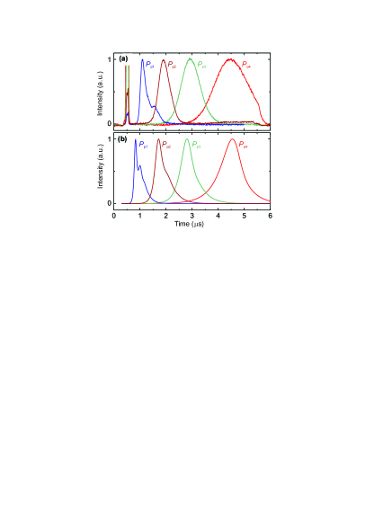
Typical experimental oscillograms demonstrating the normalized waveforms of the restored output pulse measured for different values of the pumping power are presented in Fig. 2(a). It is evident from Fig. 2(a) that the increase of the pumping power leads to a significant variation of the restored pulse parameters: decrease of the recovery time and decrease of the restored pulse duration . The experiment shows (although it is not seen in the normalized graphs of Fig. 2(a)) that the peak power of the restored pulse increases with the increase of the pumping power .
Figure 2(b) shows the profiles of the output restored pulse calculated using the theoretical model presented below. It is clear from the comparison of the experimental and theoretical waveforms presented in Fig. 2(a),(b) that this model gives a good quantitative description of the experimental data. In the following section we present a detailed description of this theoretical model.
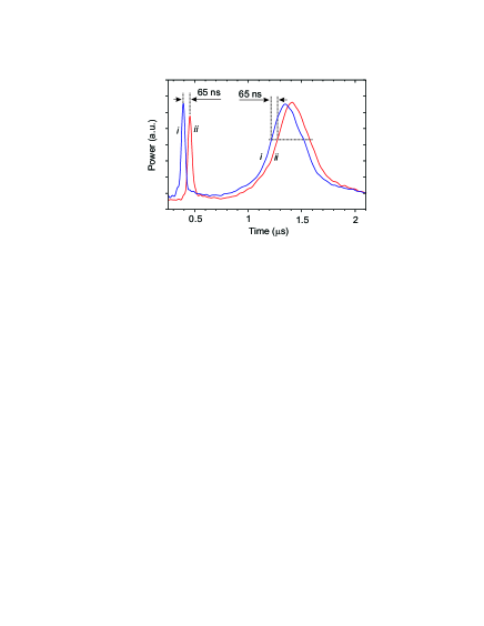
Looking at Fig. 2 one can notice that the recovery time of the restored pulse is much larger than the time of the spin wave propagation between the input and output transducers. This means that very slow spin-wave modes participate in the process of signal storage and restoration. In order to better understand the signal storage mechanism an additional experiment was performed. In this experiment an additional (second) receiving transducer was placed at a distance of 1.5 mm from the first (main) one. The time profiles of the spin-wave signal received at the main and additional transducers are presented in Fig. 3. These profiles consist of two peaks: the first narrow peak, corresponding to the propagating MSSW packet excited by the input microwave pulse, and the second broader peak, corresponding to the stored and, then, parametrically recovered spin-wave packet.
One can see that the time interval between the appearance of the fronts of these two peaks at a particular transducer is the same. This result means that the group velocities of the two delayed spin-wave packets, which are detected by the two output transducers are the same within the error margins. Thus, the excitation of the second (restored) peak at the output transducer is performed by the fast propagating MSSW mode, the same spin-wave mode that was excited initially by the input microwave pulse and which created the first narrow delayed peak at the output transducer.
The experimental result shown in Fig. 3, indicates that, apart from the propagating MSSW, a different spin-wave mode having a negligible group velocity (or, in other words, a standing spin-wave mode) must take part in the signal storage and recovery process. This standing spin-wave mode stores the information about the input microwave signal for a couple of microseconds and, then, is amplified by a parametric pumping pulse supplied to the open dielectric resonator. It is then converted into a propagating MSSW packet. Obviously, the parameter that is the most important one for this recovery process is the amplitude of the standing spin-wave mode in the immediate vicinity of the pumping resonator, as the pumping field of the resonator can only effectively interact with spin waves located near the resonator.
III Qualitative model
III.1 Dipole-exchange spin-wave spectrum of a ferrite film
To understand the mechanism governing the observed storage-and-recovery effect of a microwave signal in a ferrite film of a finite thickness let us consider the dipole-exchange spectrum of such a film in the case of the MSSW geometry, when the spin-wave carrier wave number is in the film plane and perpendicular to the bias magnetic field . A calculated spin-wave spectrum for this case is shown in Fig. 4(b). It consists of a dipole-dominated (Damon-Eshbach-like Magnetostatic_Modes_of_Ferromagnetic_Slab ) spin-wave mode, having the largest group velocity, and a series of exchange-dominated thickness spin-wave modes of the film having very low group velocities (see Kalinikos86 for details). These exchange-dominated modes are close to the standing thickness modes of a spin-wave resonance of the film, and in the simple case of unpinned surface spins these modes have discrete values of the perpendicular (to the film plane) wave vector defined as , where . Near the crossing points of the lowest () and higher-order spin-wave modes the dipolar hybridization of the spin-wave spectrum takes place, and the so-called “dipolar gaps” in the spin-wave spectrum of the film are formed Kalinikos86 .
The qualitative picture of the storage and recovery of the microwave signal in ferrite film looks as follows. A relatively short (duration 100 ns) input microwave pulse supplied to the input transducer excites a packet of propagating MSSW in the ferrite film waveguide. Under the conditions of our experiment the frequency separation between the discrete quasi-standing spin-wave modes of the film spectrum is around 10-20 MHz, depending on the mode number . At the same time, the width of the frequency spectrum of a relatively short (duration 100 ns) input microwave pulse, which excites a propagating MSSW packet in the film, is several times larger. Therefore, this packet can simultaneously excite several quasi-standing spin-wave modes in the film. Due to their extremely low group velocity these quasi-standing spin-wave modes do not propagate away from the point where they are excited. Instead, they form a “trail” along the path of the propagating MSSW packet, and this “trail” exists for over a microsecond after the MSSW packet itself is gone from the film.
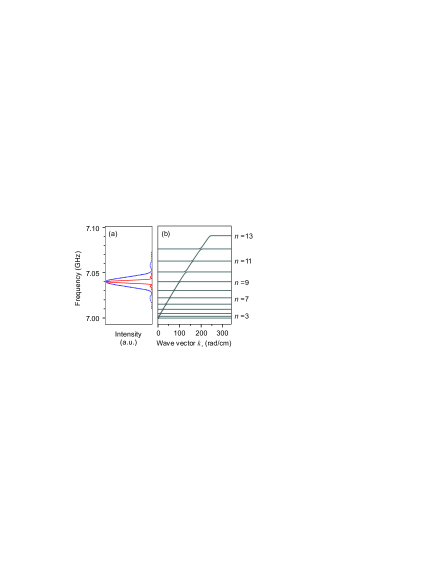
It is worth noting, that the “trail” of quasi-standing spin-wave modes is excited mainly in the spectral regions of frequency hybridization (“dipolar gaps”) in the dipole-exchange spectrum of the film (see Fig. 4) Kalinikos86 . The amplitude of this ”trail” decays exponentially with time due to the natural magnetic dissipation in the film.
To observe the restoration of the microwave signal from the “trail” it is necessary to supply the pumping pulse at the time, when the “trai” has not yet decreased to the thermal level. When the pumping is applied, the amplitudes of the quasi-standing spin-wave modes forming a “trail” start to increase due to the parametric amplification. If the pumping pulse is long enough, so that the pumping has a relatively narrow frequency spectrum and is, therefore, frequency-selective, only one quasi-standing spin-wave mode is amplified parametrically.
The increase of the amplitude of this quasi-standing mode is, eventually, limited by nonlinear spin-wave interaction processes that will be discussed in detail below. One of the most important nonlinear processes of this kind is the interaction of the parametrically amplified quasi-standing dipole-exchange spin-wave mode with the packet of exchange-dominated spin waves, that are excited by the parallel pumping from the thermal level JETP-99 .
At the same time, the back-conversion of the parametrically amplified quasi-standing spin-wave mode into a propagating MSSW packet takes place in the frequency interval near the ”dipole gap” that is resonant with the pumping carrier frequency. This process results in the formation of the restored microwave signal at the output transducer (see the waveform “iv” in Fig. 1).
We would like to emphasize one more time, that the restored delayed pulse (waveform “iv” in Fig. 1) is not a product of a direct parametric amplification of the propagating MSSW packet, since it can be observed even if the pumping pulse is supplied after the input MSSW has passed the pumping resonator. Moreover, at a given carrier frequency of the input microwave pulse, the recovered pulse is observed only if the half-frequency of the microwave pumping lies inside a narrow frequency interval close to the position of one of the the dipole gaps in the frequency spectrum of the magnetic film (see e.g. Chapter 7 in Magnetization_Oscillations_and_Waves and Kalinikos86 ). The observation of the restored spin-wave packets only in these narrow frequency intervals suggests that the process of storage and restoration of the initial microwave signal is caused by the excitation of the discrete thickness-related quasi-standing spin-wave modes of the magnetic film.
III.2 Storage and restoration of a signal as a multi-step process involving several groups of spin waves
In order to explain the above described signal restoration effect a model of interaction of two magnon groups with parametrical pumping was proposed in PRL_restoration . In this model we analyze the interaction between the electromagnetic parametric pumping with effective amplitude and frequency (where is a variable pumping magnetic field, is the parametrical coupling coefficient), standing spin-wave mode with effective amplitude characterized by the magnon number and frequency , and, the so-called, “dominating” spin-wave group with effective amplitude characterized by the magnon number and frequency . In this model the condition for the energy conservation S-theory_Lvov_book is always fulfilled automatically, because the frequency of all the waves taking part in the effective parametric interaction with pumping is twice smaller than the frequency of pumping. We call the group of spin waves that is excited by parametric pumping from the thermal level “dominating” because this group of waves has the smallest relaxation parameter. Therefore, if the pumping acts for a sufficiently long time, so that the system reaches a saturated stationary regime, this dominating group suppresses all the other spin waves taking part in the process of parametric interaction. The initial amplitude of the dominating group, characterized by the magnon number , is determined by the thermal noise level, while the initial amplitude of the standing spin-wave mode, characterized by the magnon number , is determined by the amplitude of the applied input signal, relaxation parameter of this mode, and the time delay between the signal and pumping pulses.
The process of signal restoration involves competition of two wave groups: the signal-induced standing wave group and the noise-induced dominating wave group, while both these groups are parametrically amplified by pumping. The relative efficiency of this parametric amplification is determined by the relaxation parameters of the wave groups, and, as it was mentioned above, the dominating spin-wave group has the smallest relaxation parameter . Thus, the amplification of this group is higher in comparison to the amplification of all the other spin-waves groups, including the standing wave group. The rapid increase of the amplitude of the dominating group of spin waves will lead to its interference with the standing spin-wave group, and, eventually, to the decrease of parametric amplification and saturation of dominating group amplitude in the stationary regime. Simultaneously, the amplitude of the standing spin-wave mode, which is competing with the dominating group for the energy from the pumping, will decrease, because in this nonlinear competition process the mode with larger amplitude (i.e. the dominating mode) will get a proportionally larger share of the pumping energy S-theory_Lvov_book .
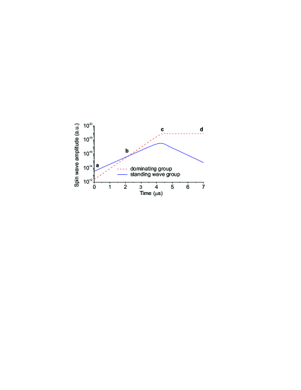
A qualitative sketch of the temporal evolution of the amplitudes of standing (solid line) and dominating (dashed line) wave groups interacting with constant-amplitude parametric pumping is presented in Fig. 5. At the initial time point, when the pumping is switched on, (point “a” in the figure) the signal-induced standing spin-wave mode (solid line) has the amplitude that is larger than the amplitude of the noise-induced dominating spin-wave group (dashed line). In the region between the points “a” and “c” the amplitudes of both wave groups exponentially increase due to the parametric amplification: the amplitude of the dominating group increases with time as , while the amplitude of the signal-induced standing wave group increases as (where are the relaxation parameters of the dominating and standing wave groups correspondingly and is the coefficient of parametric coupling between the wave group and the pumping field ).
It is clear that the amplification of the dominating group is larger, because of the smaller relaxation parameter for this wave group, and beyond the point “b” in Fig. 5 the amplitude of the dominating group overtakes the amplitude of the standing mode. Then, at the point c the amplitude of the dominating wave group reaches a certain critical value after which it starts to renormalize the effective pumping, which leads to saturation and stop of parametric amplification. The effective pumping amplitude at the saturation point “c” becomes equal to the relaxation parameter of the dominating waves with the smallest relaxation S-theory_Lvov_book .
For the conditions of our experiment this means that in the stationary regime (region between “c” and “d”). Since the amplitude of the signal-induced standing wave group start to decrease beyond the point c with the factor , as it is shown in the figure. Thus, the restored signal reaches its maximum amplitude at the time point “c”.
The mechanism of saturation of parametric amplification leading to the decrease of the restored signal amplitude can be explained in the framework of the general nonlinear theory of parametric wave interaction S-theory_Lvov_book ; Magnetization_Oscillations_and_Waves . According to this theory there are three main processes which can limit the parametric amplification: nonlinear frequency shift, nonlinear dissipation, and the so-called phase mechanism of amplification limitation. It was, however, established in S-theory_Lvov_book that it is the phase mechanism that, for the most part, limits the parametric amplification in the process of parallel pumping used in our current experiment. This phase mechanism is based on the idea that the nonlinear interaction between pairs of spin waves parametrically excited by pumping creates a nonlinear shift of their phase, which leads to the decrease of the efficiency of the pairs interaction with pumping S-theory_Lvov_book .
It is well-known, that in order to fulfill the conditions of parametric amplification of a spin wave (having wave vector and frequency ) by an external electromagnetic pumping it is necessary to fulfil the conservation laws for both energy and wave vector Parametrical_Ampl . If the pumping is quasi-uniform, i.e. the pumping wave vector is small , the interaction of the signal wave with pumping leads to the appearance of the “idle” wave which has the wave vector and forms a pair with the signal wave. The sum of phases in the pair is fully determined by the phase of the pumping according to the equation S-theory_Lvov_book :
| (1) |
where is the signal wave phase, is the idle wave phase and is the pumping phase (including the phase of the coupling coefficient between pumping and spin waves).
When the spin-wave amplitudes are small Eq. (1) can be easily satisfied as the “idle” wave with the proper phase can be chosen from the multitude of thermally excites spin waves. With the increase of the spin-wave amplitudes the pairs of the parametrically excited spin waves start to interact with each other through the four-wave process of pair interaction. As a result of this interaction process the sum of phases starts to change, the condition (1) breaks, and the efficiency of the pumping-induced parametric amplification of the signal waves is drastically reduced S-theory_Lvov_book .
In our first paper PRL_restoration describing the signal restoration process we obtained analytic expressions for the time of appearance and the amplitude of the parametrically restored pulse, but did not analyze the nonlinear processes leading to the limitation of parametric amplification and, therefore, to the finite duration of the restored pulse. Below, we present a detailed theoretical model of the signal restoration where all the relevant nonlinear processes of wave interaction are taken into account.
IV Theoretical model
In order to explain the above described effect of microwave signal restoration we use the general theory of parametric interaction of spin waves (so-called “S-theory”) S-theory_Lvov_book . The equation for the amplitude of a spin wave interacting with the parametric pumping can be written in the form (see also Magnetization_Oscillations_and_Waves ):
| (2) |
where and are the amplitudes of signal and idle waves of frequency and wave number , is the spin-wave relaxation parameter, and is the pumping frequency.
| (3) |
is a spin-wave frequency with account of nonlinear frequency shift, is the corresponding nonlinear parameter,
| (4) |
is the effective internal amplitude of parametric pumping, and is the nonlinear coefficient describing four-wave interaction of spin-wave pairs. The analogous equation for the amplitude of the idle wave is omitted for brevity.
The spin-wave formalism is substantially simplified if, instead of the individual complex amplitudes of the signal and idle waves, we introduce new variables characterizing combined amplitudes (or magnon densities per unit volume for a given wave number ) and phases of the spin-wave pairs, following S-theory_Lvov_book :
| (5) |
| (6) |
where MHz/Oe is the gyromagnetic ratio, is the Planck constant, and is the saturation magnetization.
In these “pair” variables the equations for the amplitudes of parametrically interacting spin waves can be written in a simple form S-theory_Lvov_book : equation (2) can be presented in a form:
| (7) |
In our model we analyze the existence of two magnon groups (or two effective magnon pairs): the dominating group with magnon density (note, that index is used to mark this dominating spin-wave group) and the signal-induced quasi-standing group of spin waves with magnon density PRL_restoration .
Below, we shall assume for simplicity that the coefficient of four-wave pair interaction for all the wave groups has approximately the same value , and that the effective pair phase is approximately equal for both spin-wave groups (dominating and standing) involved in the parametric interaction with pumping. Under these assumptions we can substantially simplify the expression (4) for the amplitude of the effective pumping:
| (8) |
Here and are the total number of magnons per unit of volume for the dominating and standing spin-wave groups, correspondingly, is the renormalized coefficient of pair interaction, and is the effective phase of the collective magnon pairs.
At a first glance our assumption that the effective phase of all spin-wave groups involved in the parametric interaction with pumping is approximately the same seems to be rather arbitrary. However, the theory of parametric interaction of waves S-theory_Lvov_book states, that all the excited wave groups are involved in the renormalization of the effective pumping according to Eqs. (4), (8), and that the combined effect of all these groups determines the acting amplitude of the effective pumping. Thus, as a first approximation, we can assume that the effective phases of different spin-wave groups do not differ too much.
Another significant simplification of our model is the assumption that all the wave groups participating in the parametric interaction with pumping are always in exact parametric resonance with it ( i.e. ) independently of the effective amplitude of a particular wave group. In other words, in our model we assume that the nonlinear frequency shift described by the four-wave nonlinear coefficients in Eq. 3 does not play a significant role in the parametric interaction since the wave vectors of the waves participating in this interaction are automatically adjusted to fulfil the condition of the exact parametric resonance when the effective amplitude of the wave group changes. We believe that this simplifying assumption is reasonable for the conditions of our experiment, because the frequency of pumping (or the bias magnetic field) in our experiment was always tuned in order to obtain the maximum amplitude of the restored pulse i.e. the pumping frequency or bias field were always adjusted to achieve the optimum conditions of parametric interaction.
Using all the above described simplifying assumptions, we can write the equations for the magnon densities of the two wave groups (where for the dominating spin-wave group and for the standing spin-wave group) and their common phase in the form
| (9) | |||
where MHz, MHz are the relaxation parameters for dominating and standing spin-wave groups, correspondingly. The physical meaning of the magnon densities and is simple – they characterize the effective amplitude of all the spin waves that belong to a corresponding wave group.
At first, the parametric interaction of both spin-wave groups with pumping leads only to the increase of the corresponding magnon densities and . Later, when the the increasing magnon densities become significant they start to renormalize pumping through the phase mechanism described in S-theory_Lvov_book , which leads to the limitation of the parametric amplification for the both spin-wave groups.
Let us now analyze some of the particular solutions of Eq. (IV). The simplest solution one can get is the solution for the initial quasi-linear regime, when the system is far from saturation and the influence of the excited spin wave on the pumping is negligible. It is known S-theory_Lvov_book that the phase in this case is equal . The magnon densities in this quasi-linear regime can be found as:
| (10) |
where are the initial magnon densities of the dominating and standing spin-wave groups. We note that the quasi-linear result (IV) agrees well with the previously described qualitative picture of the development of parametric interaction in our experimental system (see region between points “a” and “c” in Fig. 5).
Another particular solution of the system (IV) can be obtained in the stationary regime, when the pumping is renormalized by the excited spin waves and the system is saturated. It is clear, that in this stationary regime the magnon densities of both spin-wave groups and their common phase are constant: . If we assume that in this saturation regime and that the common spin-wave phase varies in the interval we obtain the following stationary solution of the system (IV)
| (11) | |||
The analytic result (IV) also agrees well with the above presented qualitative picture of parametric interaction with pumping and it describes the state reached by the system beyond point “d” in Fig. 5).
To get more detailed information about the temporal behavior of the magnon densities of two magnon groups we solved the systems of equation (IV) numerically, assuming that at the initial moment the phase is the same as in the quasi-linear case .
The initial value of the magnon density of the dominating spin-wave group is determined by the level of thermal noise existing at a given temperature in a ferrite film, and can be estimated using standard methods S-theory_Lvov_book . Our estimation performed assuming that the dominating spin-wave group consists of short-wavelength exchange-dominated spin waves propagating perpendicular to the direction of the bias magnetic field gave the following value for the total number of magnons per unit volume of ferrite film
This estimation does not take into account the fact that the initial microwave signal could heat-up the dominating spin-wave group even before the pumping is switched on. However, to account for this effect we need first to evaluate the number of magnons in the group of standing spin waves created by the input signal.
The estimation of the initial magnon density for the standing spin-wave group turns out to be a rather complicated task, because it involves the calculation of the transformation coefficient of the microwave signal into a propagating MSSW and, also, the coefficient of partial transformation of the MSSW into the standing (thickness) spin-wave modes of the film. It is clear, however, that the initial magnon density in the standing spin-wave group must be proportional to the power of the input microwave signal . It is also clear that as soon as the input signal pulse is gone from the film the magnon density of the standing wave group will decay exponentially with time with the exponent equal to the relaxation parameter of the standing spin waves. Thus, if the delay time between the input signal pulse and the pumping pulse is we can evaluate the magnon density in the standing spin-wave group at the initial moment of parametric amplification (i.e. at the moment when the pumping pule is switched on) as
where is the power of input signal, MHz is a relaxation parameter of the standing spin-wave group, ns is the delay time between the input sinal pulse and the pumping pulse, and is a phenomenological coefficient describing the multi-step transformation of the input microwave signal into the standing spin-wave mode. For the conditions of our experiment we evaluated the coefficient as , which means that for the input signal power =10 W the initial total magnon density in the standing spin-wave group is equal to
Thus, at the initial moment of parametric interaction with pumping the standing spin-wave group in our case is approximately 40 times stronger than the dominating spin-wave group, caused mostly by thermal magnons.
In order to make our model more realistic we need to take into account another effect that plays an important role in the process of microwave signal restoration by parametric pumping. This important effect is the effect of elastic two-magnon scattering which is always present in real magnetic systems. It leads to a partial transfer of energy from one spin-wave groups to another, while the spin-wave frequency is conserved.
Under the conditions of our experiment the effect of two-magnon scattering leads to partial transfer of energy from the standing spin-wave group (excited by the input signal) to the dominating spin-wave group. Thus, this effect amounts to an effective heating-up of the initial thermal spin wave level. This heating-up effect was investigated in a previous article Nonres_Restoration , where the nonresonant signal restoration (i.e. the process where the signal frequency was not equal to half of the pumping frequency) was investigated. Below, we shall use an approach similar to Nonres_Restoration , and we will introduce a phenomenological coefficient which accounts for this heating-up. In the framework of this phenomenological approach the initial amplitude of the dominating spin-wave group, after the application of the input signal pulse, could be evaluated as
where is a phenomenological parameter describing the efficiency of two-magnon scattering. Taking into account this two-magnon heating-up effect we were able to get a more realistic evaluation for the initial magnon density of the dominating spin-wave group in the case when the input pulse power was equal to =10 W
which means that the difference between the initial amplitudes of the standing and the dominating wave groups in our experiment was about 15 times.
Another important feature of our model is the account of nonlinear dissipation in the standing (signal-generated) spin-wave group. In contrast with the dominating spin-wave group, excited mostly by the thermal noise and having arbitrary phases of individual spin waves, the standing spin-wave group is coherent, and all the spin-wave phases in this wave group are determined by the phase of the input signal. Thus, the spin waves in the standing spin-wave group can effectively participate in four-wave (second-order) parametric interactions both within the group and with the spin waves belonging to other groups. This interaction leads to an effective transfer of energy from the standing spin-wave group, that can be phenomenologically described as nonlinear dissipation by the following form:
The coefficient of nonlinear damping for the conditions of our experiment was evaluated as .
As it was mentioned in the previous section, the nonlinear damping of spin waves is one of the possible mechanisms leading to the limitation of parametric amplification. However, we would like to stress one more time, that in our experiments the nonlinear damping of the standing wave group, described by the coefficient , played a relatively minor role, and the limitation of parametric amplification was mainly caused by the phase mechanism S-theory_Lvov_book described in our model (IV) by the nonlinear coefficient .
The coefficient of the nonlinear four-wave interaction between the pairs of excited spin waves was calculated using the expressions presented in Magnetization_Oscillations_and_Waves to give .
The pumping magnetic field was calculated from the experimental power of the pumping pulse as , where s W is the coefficient which describes the efficiency of the open dielectric resonator through which the pumping pulse was supplied to the ferrite film in our experiment.
The model (IV) with the initial conditions and parameters described above was solved numerically to describe the temporal evolution of the amplitudes of two wave groups participating in the parametric interaction with pumping.
V Results and discussion
The results of the numerical solution of the system of equations (IV) for the above specified parameters are presented in Fig. 2, Fig. 6, Fig. 7 and Fig. 8. We shall discuss below each of these figures.
V.1 Temporal dynamics of the parametric interaction process

The temporal dynamics of parametric interaction of the two excited spin-wave groups with constant-amplitude pumping that was switched on abruptly at time is illustrated by Fig. 6. The upper frame demonstrates the evolution of the collective spin-wave phase and the amplitude of the renormalized effective parametric pumping, while the lower frame of Fig. 6 illustrates the evolution of the magnon densities and of the dominating and standing spin-wave groups, respectively.
The numerical results presented in Fig. 6 clearly confirm the qualitative picture of the parametric interaction shown in Fig. 5.
In the initial time interval ( s) a quasi-linear parametric amplification of the both spin-wave groups takes place. In this quasi-linear regime the effective spin-wave phase , the effective pumping is not significantly renormalized and is practically equal to , while the magnon densities and are very well described by the analytical result (IV).
At the final stage of parametric interaction (s), when the system reaches stationary (or saturation) regime, we also recover the above derived analytic result (IV). In this stationary regime the effective pumping is strongly renormalized by the excited spin waves, and is stabilized at the value , at which it just compensates the losses of the dominating spin-wave group. Under these conditions the magnon density of the dominating spin-wave group becomes constant, while the magnon density of the standing spin-wave group vanishes.
In the transitional region ( s s) the amplitude of the standing spin-wave group first increases, and then begins to decrease, which results in the appearance of a finite-duration restored pulse at the output of the system. The theoretically calculated profiles of the restored output microwave pulse shown in Fig. 2(b) practically repeat the temporal profile of the magnon density of the standing spin-wave group shown in the lower frame of Fig. 6.
V.2 Restored signal parameters vs pumping power
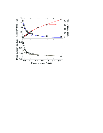
As it was mentioned above, the characteristics of the restored microwave pulse, such as the peak power, duration, and delay time, are mainly determined by the process of parametric interaction with pumping. This fact is illustrated by Fig. 2(a), where the experimental normalized profiles of the restored pulses are presented for different values of the pumping power. In Fig. 2(b) calculated normalized profiles of the restored pulse are presented for the same pumping powers. It is clear from this figure, that with increasing pumping power both the delay time and duration of the restored pulse decrease. This effect can be easily explained by the fact that in case of higher pumping power the system saturates (i.e. reaches a stationary regime) faster, and, as a result, the restored microwave pulse appears earlier.
The experimental (symbols) and theoretical (solid lines) dependencies of the peak power , recovery time , and duration of the restored pulse on the pumping power are shown in Fig. 7. It is evident that the increase of the pumping power leads to decrease of and , and, at the same time, to the increase of the peak power of the restored signal. The above shown behavior of the restored pulse peak power can be explained by that fact that with increasing pumping power the amplification rates and become closer and the difference in the peak amplitudes of the standing and dominating spin-wave groups becomes smaller. Thus, as a result, the amplitude of the restored pulse becomes larger.
It is clear from Fig. 7 that the theoretical results for the restoration time and power of the restored pulse are in good agreement with experiment. At the same time, the calculated dependence of the restored pulse duration on the pumping power agrees with the experiment only qualitatively. We believe that a significantly better description of the experimental results could be achieved if the theoretical model is modified to take into account such experimental parameters as the finite duration of the input signal, realistic widths of the dipole-exchange gaps in the ferrite film spectrum, and the frequency selective character of the parametric amplification process.
V.3 Restored signal parameters vs input signal power
Using our theoretical model we also calculated the influence of the input signal power on the parameters of the restored microwave pulse.
According to the simple analytical model presented in PRL_restoration where the increase of the input signal power the power of the restored pulse increases linearly, while the recovery time should remain constant.
At the same time, our experiments (see Fig. 8) clearly demonstrate that the increase of the input signal power leads to decrease of the recovery time and to increase of the restored pulse power , with the experimentally observed increase being not linear.

It is evident from Fig. 8 that our new theoretical model (IV) describes the experiment rather well and, therefore, significantly improves the simple analytical model presented in PRL_restoration . There are two reasons why our new model (IV) improves the accuracy of the theoretical description. First of all, in the analytical model PRL_restoration only the dominating spin-wave group participates in the process of saturation of the parametric amplification, while in reality both spin-wave groups significantly influence the saturation process. Another reason, which also plays an important role in the parametric interaction process, is the heating of the thermal magnons by the input signal (see Nonres_Restoration for details). This effect was taken into account in the model by the introduction of the phenomenological coefficient .
VI Summary and conclusion
In conclusion, we investigated the effect of storage and recovery of a microwave signal in a ferrite film having discrete dipole-exchange spin-wave spectrum. The signal is stored in the form of standing spin waves (thickness modes) excited by the input microwave pulse in the frequency intervals near the dipole-exchange gaps in the spin-wave spectrum of a ferrite film. The signal is recovered in the process of parametric interaction of these standing spin-wave modes forming a trail of the input pulse with a long and powerful pumping pulse having the carrier frequency that is close to the double frequency of one of the dipole-exchange gaps in the ferrite film spectrum. An approximate (mean field) theoretical model, taking into account the competition of two spin-wave groups interacting with parametric pumping, and involving a nonlinear phase mechanism of limitation of parametrical amplification was used to describe the experimental results. The developed model provides a good quantitative description of the experimentally observed effect of storage and recovery of microwave pulses in ferrite films.
This work was supported by the Deutsche Forschungsgemeinschaft (SFB/TRR 49), by the Ukrainian Fund for Fundamental Research (25.2/009), by the MURI grant W911NF-04-1-0247 from the U.S. Army Research Office, and by the Oakland University Foundation.
References
- (1) A. Korpel and M. Chatterjee, Proc. IEEE 69, 1539 (1981).
- (2) G.A. Melkov, A.A. Serga, V.S. Tiberkevich, A.N. Oliynyk, and A.N. Slavin, Phys. Rev. Lett. 84, 3438 (2000).
- (3) G.A. Melkov, Yu.V. Kobljanskyj, A.A. Serga, V.S. Tiberkevich, and A.N. Slavin, Phys. Rev. Lett. 86, 4918 (2001).
- (4) Yu.V. Kobljanskyj, V.S. Tiberkevich, A.V. Chumak, V.I. Vasyuchka, G.A. Melkov, and A.N. Slavin, J. Magn. Magn. Mater. 272, 991 (2004).
- (5) A.A. Serga, A.V. Chumak, A. Andre, G.A. Melkov, A.N. Slavin, S.O. Demokritov and B. Hillebrands Phys. Rev. Lett. 99, 227202 (2007).
- (6) V.S. L’vov, Wave Turbulence under Parametric Excitations. Applications to Magnetics. (Springer-Verlag, 1994)
- (7) R.W. Damon and J.R. Eshbach, J. Phys. Chem. Solids 19, 308 (1961).
- (8) A.G. Gurevich and G.A. Melkov, Magnetization oscillations and waves (CRC Press, New York, 1996).
- (9) B.A. Kalinikos and A.N. Slavin, J. Phys. C 19, 7013 (1986).
- (10) G.A. Melkov, A.A. Serga, V.S. Tiberkevich, A.N. Oliynyk, A.V. Bagada, and A.N. Slavin, J. Exp. Theor. Phys. (JETP) 89, 1189 (1999).
- (11) A.A. Serga, B. Hillebrands, S.O. Demokritov, A.N. Slavin, P. Wierzbicki, V. Vasyuchka, O. Dzyapko, and A. Chumak, Phys. Rev. Lett. 94, 167202 (2005).
- (12) S. Schäfer, A.V. Chumak, A.A. Serga, G.A. Melkov, and B. Hillebrands, Appl. Phys. Lett. 92, 162514 (2008).