The Casimir effect in the nanoworld
Abstract
The Casimir effect is a force arising in the macroscopic world as a result of radiation pressure of vacuum fluctuations. It thus plays a key role in the emerging domain of nano-electro-mechanical systems (NEMS). This role is reviewed in the present paper, with discussions of the influence of the material properties of the mirrors, as well as the geometry dependence of the Casimir effect between corrugated mirrors. In particular, the lateral component of the Casimir force and restoring torque between metal plates with misaligned corrugations are evaluated.
I Introduction
The Casimir force was predicted in by H.B.G. Casimir as an attractive force between two perfectly reflecting, plane and parallel mirrors in vacuum Casimir48 . The force has been measured in different experiments with an increasing control of the experimental conditions Sparnaay89 ; Lamoreaux97 ; Mohideen98 ; Harris00 ; Ederth00 ; Bressi02 ; Decca03prl ; ChenPRA04 ; DeccaAP05 ; Decca07 . This has been considered as an important aim which should allow an accurate comparison between theoretical predictions and experimental observations Milonni94 ; LamoreauxResource99 ; Reynaud01 ; GenetIAP02 ; LambrechtPoincare . These advances have been reviewed in a number of papers, for example LambrechtPoincare ; Bordag01 ; Milton05 and in a special issue of the New Journal of Physics NJP06 .
Meanwhile, it has been realized that the Casimir force was a dominant force at micron or sub-micron distances, and then clearly an important aspect in the domain of micro- and nano-oscillators (MEMS, NEMS) BuksPRB2001 ; ChanScience2001 ; ChanPRL2001 now emerging from modern nanofabrication techniques EkinciRSI2005 . If the Casimir force has been primarly considered as a source of stiction between mobile parts, it is now recognized as an essential source of actuation to be used in the design of MEMS and NEMS.
In both fundamental and technological contexts, it is extremely important to take into account the real experimental situations which largely differ from the ideal conditions considered by Casimir. We review below some theoretical tools which have shown their efficiency for a general formulation of the Casimir effect, accounting for the material properties of the interacting plates as well as for the effect of non planar boundary geometries.
II Idealized Casimir force
The Casimir force and energy between two perfectly reflecting, plane and parallel mirrors immersed in quantum vacuum have the following forms
| (1) |
These expressions correspond to an attractive force and a binding energy . Remarquably, they depend only on geometrical quantities, the area of the mirrors and their distance (), and fundamental constants, the Planck constant and the speed of light .
III Imperfect reflection
Experiments are performed with real metallic mirrors which good reflectors only at frequencies below their plasma frequency which depends on the properties of the conduction electrons in the metal. The effect of imperfect reflection on the Casimir force and energy has been recognized long time ago Lifshitz56 ; Schwinger78 though it has been described with good accuracy only recently Lamoreaux99 ; Lambrecht00 ; KlimPRA00 . We recall below the scattering theory of the Casimir force which has been developed and used to this aim Jaekel91 ; GenetPRA03 ; LambrechtNJP06 .
We begin with perfectly plane and parallel mirrors, separated by a distance . The two mirrors form a Fabry-Perot cavity and the fluctuations of the intracavity fields propagating back and forth along the cavity axis can be calculated in terms of the fluctuations of the incoming free-space fields. The field modes are characterized by their frequency , transverse wavevector with components in the plane of the mirrors, and by their polarization . Time invariance of the problem, as well as transverse spatial translation invariance (along and ) ensure that the frequency, the transverse wavevector and the polarization are conserved quantities throughout the scattering process on the cavity. The scattering couples only the free vacuum modes with opposite signs for the component of the wavevector along the longitudinal axis of the cavity. We write the reflection amplitude of the mirror as seen from the inner side of the cavity. These amplitudes obey general physical properties of causality, unitarity and high frequency transparency.
The spectral density of the vacuum intracavity fields is changed with respect to that of free-fields outside the cavity. The ratio of energy inside the cavity to energy outside the cavity is fixed, for a given mode, by the following function
| (2) |
This statement constitues a theorem which has been demonstrated for lossless as well as lossy mirrors GenetPRA03 ; Barnett96 . It does not depend on the state of the fields and is therefore valid for vacuum fluctuations as well as for thermal fluctuations, assuming thermal equilibrium. We do not discuss here the issue of thermal dependence of the Casimir effect (see for example the recent review Brevik06 ) and restrict our attention to the zero temperature limit.
The force is the difference in radiation pressure between inner and outer faces of the mirrors, integrated over all the modes. Using analyticity properties, the force and energy may be written as integrals over imaginary frequencies
| (3) |
is the longitudinal component of the wavevector evaluated for imaginary frequencies.
The expressions (3) are regular for any physical model of the reflection amplitudes. High frequency transparency of any real mirror ensures that the integrals are convergent, and free from the divergences usually associated with the infinitness of vacuum energy. They reproduce the Lifshitz expression for the Casimir force Lifshitz56 ; Schwinger78 when assuming that the metal plates have large optical thickness with reflection amplitudes given by the Fresnel laws on the vacuum-bulk interface
| (4) |
Here is the dielectric function describing a optical response of the material inside the mirrors. Taken together, relations (3) and (4) reproduce the Lifshitz expression Lifshitz56 . They are known to tend to the original Casimir expression in the limit which produces perfectly reflecting mirrors Schwinger78 .
We may emphasize at this point that relations (3) are more general than Lifshitz expression which, incidentally, were not written originally in terms of reflection amplitudes Katz77 . They are valid for example for non-local optical responses of the mirrors provided the reflection amplitudes are substituted by their possibly more complicated expressions. The only limitation, discussed below, is associated with the assumption of specular scattering.
IV Finite conductivity corrections
We now review the corrections to the Casimir expression coming from the finite conductivity of the bulk material. Here, these corrections are deduced from relations (3), assuming Fresnel laws (4) for a local optical response of the bulk material. This function may be given by a simple description of the conduction electrons in terms of a plasma model
| (5) |
characterized by a plasma frequency and wavelength . It may be given by a more realistic representation based upon tabulated optical data and which includes the contribution of interband electrons Lambrecht00 .
The corrections to the Casimir effect are conveniently represented in terms of factors measuring the reduction of the force and energy with respect to the ideal limit of perfect mirrors
| (6) |
The results of the calculations are plotted on Fig.(1) for Au-covered mirrors. They are shown as varying versus the ratio of the cavity length to the plasma wavelength .

For metals used in recent experiments, the plasma wavelength lies around m (nm for Au and Cu). At large distances , the ideal Casimir formula is recovered (), as expected. At short distances, a significant reduction of the force is obtained, with a change in the power law for the variation of the force with distance. This change can be understood as the result of the Coulomb interaction of surface plasmons at the two vacuum interfaces GenetAFLdB04 ; Henkel04 . This interpretation may be actually generalized to arbitrary distances at the price of a full electromagnetic treatment of the plasmonic as well as ordinary photonic modes Intravaia05 ; Intravaia07 . The plasma model is sufficient for a first description of the variation of the force with distance but it is not sufficient for a precise comparison.
First, the relaxation of the conduction electrons has to be accounted for. Then, interband transitions are reached for metals like Au, Cu or Al for photon energies of a few eV and their effect on the optical response has to be taken into account for evaluating the Casimir force at short (sub-micron) distances. This can be done by using tabulated optical data which are integrated using causality relations Lambrecht00 . The result of the corresponding evaluation is shown on Fig.(1). It is worth stressing that calculations are sensitive to the existing differences in optical data between different tabulated sets Pirozhenko06 . This means that an imperfect knowledge of the optical properties of the mirrors used in the experiment is a source of uncertainty in the experiment-theory comparison. Ideally, if the aim is to have a reliable theoretical evaluation of the Casimir force to be compared with experiments, it is necessary to measure the reflection amplitudes in situ.
V Silicon slab mirrors
As stressed in the introduction, the relevance of the Casimir effect on nanosystems calls for a precise understanding not only of the influence of material optical properties on the Casimir force, but also of the influence of geometrical parameters, such as the thickness of the coatings IannuzziPNAS2004 ; LisantiPNAS2005 or the thickness of the mirrors themselves. In this context, structures made of silicon, the reference material used in nano-fabrication processes, are particularly interesting to study LambrechtEPL2007 ; Chen07 .
The reflection amplitude corresponding to a slab of finite thickness is different from the bulk expression and is given through a Fabry-Perot formula
| (7) |
is the bulk reflection amplitude given by (4). Using these reflection amplitudes for calculating the Casimir force between two Si slabs, interesting behaviours have been noted LambrechtEPL2007 which differ from the situation of metallic mirrors. In particular, it was shown that the material thickness has a stronger influence on the Casimir force for Si slabs than for Au slabs. For Si, the force decreases as soon as the slab separation is larger than the slab thickness , as seen on Fig.(2).
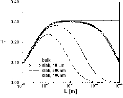
In contrast to metals which become perfect reflectors in the limit of zero frequency, Si is a semiconductor with a finite transverse plasma frequency corresponding to a cut-off wavelength nm. For cavity length smaller than this cut-off wavelength, Si tends to become transparent. The associated optical thickness given in Eq.(7) is large, so that the Si slab behaves like a bulk Si mirror with low reflectivity at high frequency. The Casimir force is then much smaller than the perfect reflection limit of Eq.(1). On the other hand, at low frequencies , one will have together with , low frequencies being predominant at large distances. In this latter case, the slab is transparent again, and the Casimir force between two Si slabs is decreased when . This result can have interesting consequences for nanostructures as it opens a way to control the magnitude of the Casimir force and possibly eliminate an unwanted Casimir source of stiction. From a fundamental point of view, it also offers a new solution to study the comparison between experiment and theory of the Casimir force Chen07
VI Geometry and the Casimir effect
Geometry effects are expected to lead to a rich variety of behaviours in the Casimir physics Balian7778 ; Plunien86 ; Balian0304 . Recent advances make it possible to explore this interplay, both from experimental and theoretical point of views. This also offers new possibilities for tailoring the Casimir force through specific designs EmigEPL03 .
Force and energy evaluations between non planar mirrors are commonly obtained using the so-called proximity-force approximation (PFA) Derjaguin68 ; Langbein71 . This approximation amounts to an averaging of plane-plane contributions over the distribution of local interplate separations defined by the chosen geometry. For the energy, the PFA leads to
| (8) |
with and the surface profiles of each mirrors. Such profiles can be described by their spectra evaluated over the surface of the mirrors
| (9) |
with the Fourier transform of , and by the associated correlation lengths . When they are smaller than the other length scales, the amplitudes of deformations can be considered as perturbations. A second order expansion in the profiles can thus be performed leading to
| (10) |
The trivial first-order term has been discarded, assuming that the deformations have zero spatial averages .
The evaluation of the effect of geometry through the PFA, based on a summation procedure over local contributions assumes some additivity property of the Casimir effect, whereas the Casimir force is known not to be additive. The PFA can only be accurate for surfaces which can be considered as nearly plane with respect to other scales such as the separation distance GenetEPL03 . For example, it allows one to calculate the Casimir force in the plane-sphere (PS) configuration as
| (11) |
where is the Casimir energy in the plane-plane (PP) geometry. Most recent experiments are performed in the plane-sphere geometry which is much simpler to control than the plane-plane configuration. The PFA is here expected to be valid provided the radius of the sphere is much larger than the distance of closest approach.
But the PFA certainly fails for describing more general surface profiles. As far as plate deformations are concerned, it can only be valid in the limit which corresponds to a trivial specular description of the reflection process on the surfaces MaiaNetoPRA05 . For the general case, a description of non specular scattering process on mirrors is available for analyzing the connection between geometry and the Casimir effect MaiaNetoPRA05 . An expression for the Casimir energy between parallel mirrors with arbitrary surface profiles has been derived in LambrechtNJP06 ; RodriguesPRA2007
| (12) |
This expression is based on non-specular reflection matrices and associated to each mirror. While the operator corresponds to propagation of the field between the two mirrors, and is diagonal in the plane-wave basis with elements given by , the two matrices and are non-diagonal on plane-waves. This corresponds to a mixing of polarizations and wavevectors, due to non-specularity diffraction on the gratings formed by the profiles on the surfaces of the mirrors.
As it is reviewed below, this formula (12) has been used to evaluate the effect of surface roughness MaiaNetoPRA05 or corrugations on the Casimir force RodriguesEPL2006 ; RodriguesPRL2006 . Analytical expressions have been derived through a perturbative treatment, with the roughness or the corrugation amplitudes taken as the smallest length scales involved in the problem. The effect of the optical response of the metal has been included in these calculations. It is worth stressing that this formula has a wider range of validity. It can in principle describe structured plates with large corrugation amplitudes, as well as material properties not limited to a simple plasma model. The only task for a quantitative evaluation of the Casimir force or energy is to obtain the actual form of the reflection operators and to be inserted into Eq.(12).
VII Roughness correction
A correction to the Casimir force that must be accounted for is the effect of surface roughness, intrinsic to any real mirror. This effect is analyzed in recent experiments through procedures based on the PFA BordagPLA95 ; KlimPRA99 . The general formula (12) has been used to go beyond this approximation MaiaNetoPRA05 . As already stressed, the roughness amplitude must be the smallest length scale for perturbation theory to hold. Meanwhile, the plasma wavelength, the mirror separation and the roughness correlation length may have arbitrary relative values with respect to each other.
We remind that the roughness profiles are defined with respect to reference mirror planes separated by the mean distance . We assume that profiles have zero averages and show no cross-correlations. We also suppose that the area of each plate is large enough to include many correlation areas (), so that surface averages are identical to statistical averages. Up to second order in the profiles, the correction to the Casimir energy may thus be written as follows
| (13) |
Here corresponding to the roughness spectrum added over the two plates. is a spectral sensitivity to roughness of the Casimir energy. Due to cylindrical symmetry with respect to rotations in the transverse plane, it only depends on . This dependence reveals that the roughness correction does not only depend on the root-mean-square (rms) roughness, but also on the spectral distribution of the roughness. Fig.(3) displays normalized by as it has been calculated for Au-covered mirrors and for various interplate distances.
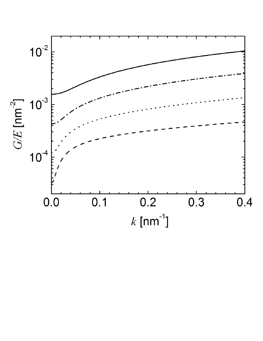
The rich behaviours of as a function of the length scales is discussed in MaiaNetoEPL05 .
What we want to stress here is that this function describes deviations from the PFA. The width of the roughness spectrum is indeed fixed by the inverse of the correlation length . When this spectrum is contained in the region where remains close to its secular limit , we can approximate Eq.(13) as proportional to the rms roughness
| (14) |
This corresponds effectively to the PFA expression, as the consequence of a theorem which was proved in MaiaNetoPRA05
| (15) |
Equation (15) is nothing but a properly stated “Proximity Force Theorem”. It can however not be confused with the “Proximity Force Approximation” (14) which is a good approximation only for smooth enough mirrors, that is also for large enough roughness correlation lengths .
In the general case, the PFA result (14) underestimates the effect of roughness. When performing the theory-comparison, one has therefore to carefully assess the roughness correction by measuring the roughness spectra in situ and using the roughness sensitivity function as given in MaiaNetoPRA05 ; MaiaNetoEPL05 . The PFA can only be used if has been proven to be large enough or, in a looser way, when the roughness correction has been estimated to have a negligible value.
VIII Lateral force between corrugated plates
As the roughness effect remains a small correction to the Casimir force, it seems difficult to measure the deviation from PFA regime and check its agreement with theory. Fortunately, there exists an experimental configuration showing more promising perspectives as a potential probe of the non-trivial interplay between the Casimir effect and geometry.
This configuration corresponds to periodically corrugated metallic plates placed face to face in vacuum, so that a lateral component of the Casimir force arises due to the breaking of the transverse translational invariance Golestanian . A recent experiment has demonstrated the feasibility of a lateral force measurement at separation distances of the order of nm ChenPRL02 . Since it would disappear in the absence of corrugation, the lateral force should not be considered as a small correction to the otherwise dominant normal Casimir force, as it was the case for the study of roughness. As we will see below, the deviation from PFA indeed appears as a factor in front of the lateral force, so that a precise measurement of this force would test in a crucial manner the interplay between Casimir effect and geometry RodriguesPRL2006 . As the experiments are performed at short distances, it cannot be described with the assumption of perfect reflection, where analytical results are available EmigPRA03 ; EmigPRL05 . Again, the general scattering formula (12) shows the ability to give an estimation for the lateral force for arbitrary relative values of the length scales , and , provided the corrugation amplitudes remain the smallest length scales of the problem.
We consider two metallic mirrors, both sinusoidally corrugated along one dimension, with the same corrugation wavelength , separated by a distance and facing each other with a relative spatial mismatch between the corrugation crests -see Fig.(4).
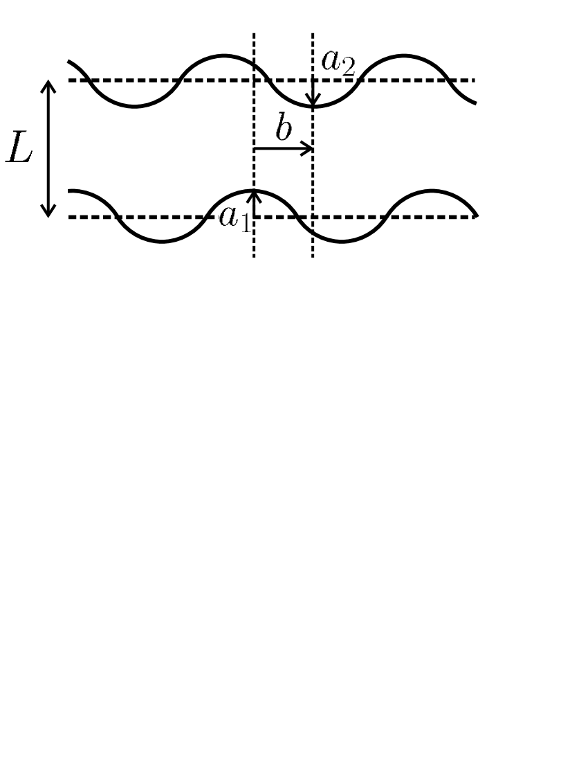
The profiles , , of the two uniaxial (along ) corrugated mirrors are defined by the two functions and with the wavevector associated to the corrugation wavelength . We take both profiles with zero spatial averages. At the second order in the corrugations, cross-terms of the form appear which contribute to the lateral force because the energy depends on the transverse mismatch .
This fact, a consequence of the correlation between the two corrugation profiles, induces a contrast with the case of roughness where the effect was associated with quadratic terms . It implies that the evaluation of the lateral force only involves first-order non-specular amplitudes calculated on each mirror separately. The full calculation gives the second-order correction to the Casimir energy induced by the corrugations
| (16) |
The function is given in RodriguesPRL2006 and does only depend on the modulus of . Here again, the PFA regime is recovered in the limit, as a consequence
| (17) |
This theorem is ensured, for any specific model of the material medium, by the fact that is given for by the specular limit of non-specular reflection amplitudes MaiaNetoPRA05 .
In order to compare with experiments, we consider the expression of the lateral force in the plane-sphere configuration. It is derived from the plane-plane configuration using the PFA, reliable as long as . In fact, there is no interplay between curvature and corrugation provided , a condition met in the experiment reported in ChenPRL02 .
From Eq.(11), the lateral force in the plane-sphere geometry is eventually given as RodriguesPRL2006
| (18) |
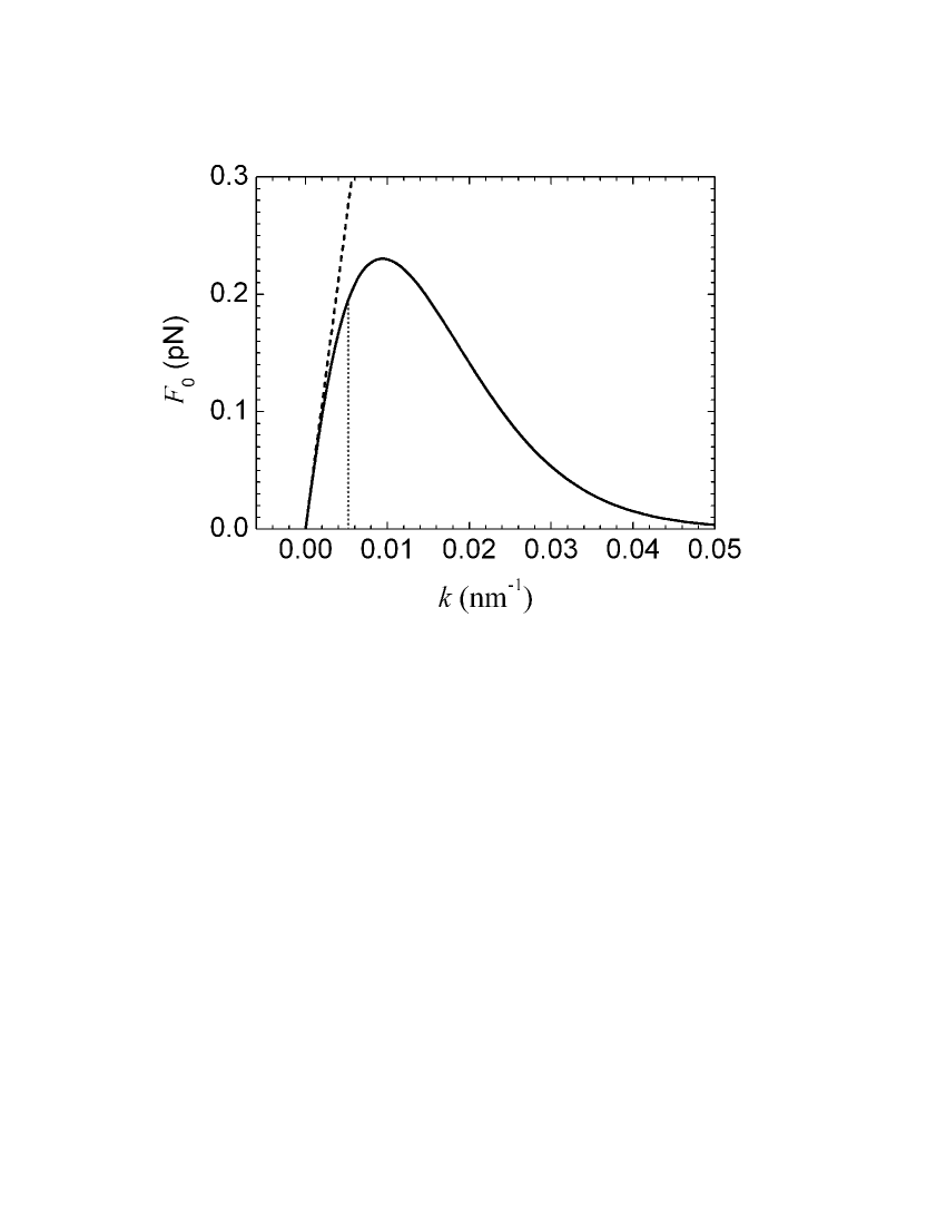
The force is plotted in Fig.(5) as a function of , with length scales , and fitting the experimental values ChenPRL02 . As the corrugation amplitudes are not small enough in the experiment to meet the perturbation condition, the theory and experiment can unfortunately not be compared directly. The plot on Fig.(5) nevertheless shows the interesting fact that the length scales taken from the experiment, with indicated by the vertical dashed line, clearly fall outside the PFA sector in the perturbative calculation. For related implications, we refer the reader to the discussions in RodriguesPRA2007 .
It appears clearly on the figure that the PFA overestimates the magnitude of the lateral force for arbitrary . We also note that the PFA prediction for the force scales as when increases from zero. At larger values of in contrast, the lateral force decreases. This is due to the one-way propagation factor separating the two first-order non-specular reflections at each plate, given as a decresing exponential in the high limit RodriguesPRL2006 . It follows that there is a maximal force when is varied. It corresponds to nm-1 with the other length scales corresponding to the experiment. The ratio is thus falling outside the PFA sector which confirms that a lateral force measurement is an excellent candidate for probing deviations from the PFA.
IX Torque
Another interesting observable for exploring the non-trivial geometry dependence of the Casimir energy is the torque arising when the corrugations of the two plates are misaligned. With this angular mismatch between the corrugations, rotational symmetry is broken and induces a restoring torque between the plates.
The calculations are quite similar to those which were done for aligned corrugated surfaces, in particular because the same non-specular reflection coefficients are used to describe each plate. The second-order correction is still given by the sensitivity function which does only depend on the modulus of the corrugation wavevector . The difference with the lateral force case lies only in the fact that the corrugation profiles corresponds to different corrugation wavevectors having however the same modulus . The angular mismatch between and is given by the angle . The parameters represent lateral displacements with respect to the configuration with a line of maximum height at the origin. We assume that the corrugation is restricted to a rectangular section of area centered at and much larger than so that diffraction at the borders can be neglected. With these assumptions, and in the limit of long corrugation lines with smaller or of the order of , the energy correction per unit area is given in RodriguesEPL2006 as
| (19) |
The spatial coefficient is the relative lateral displacement along the direction . As expected by symmetry, this correction is invariant under the transformation and due to the fact that the corrugation lines have no orientation. The case corresponds to the result of pure lateral displacement discussed in the preceding section.
The scale of the energy variation with and is set by the parameter . In fact, if plate is released after a rotation of , its subsequent motion is a combination of rotation and lateral displacements. Rotation is favored over lateral displacements for (see Fig.(1) in RodriguesEPL2006 ). The torque is evaluated in RodriguesEPL2006 for corrugated Au mirrors, with corrugation amplitudes nm, corrugation length m and separated by a distance of m. It is maximum at and is plotted in Fig.(6) as a function of . It starts increasing linearly with in the PFA sector and for the same reason as the lateral force, it decreases exponentially in the high- limit.
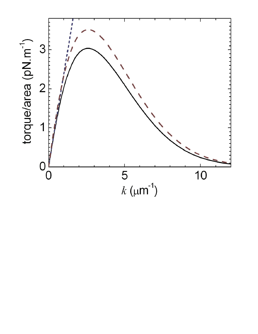
As is clear on Fig.(6), the PFA overestimates the magnitude of the torque by a factor of the order of at the peak value of the torque. The discrepancy even increases with , since smaller values of correspond to smoother surfaces. The conditions are gathered up towards a direct experimental evidence of a non-trivial effect of geometry.
Fig.(6) also displays the torque when evaluated between perfect metallic corrugated mirrors EmigPRA03 . The corresponding deviation with respect to the calculation given by Eq.(19) stresses that at a separation distance of m, the optical response of the metal must be accounted for in an accurate evaluation of the torque. The perfect conductor limit is reached only if the plasma wavelength is the smallest length scales (apart from the corrugation amplitudes) of the problem.
X Conclusion
New perspectives for studying the interplay between Casimir effect and geometry are today clearly visible. The theoretical formalism is better and better mastered, so that a rich variety of configurations can be studied. Meanwhile, novel experimental capabilities are available, allowing one to address challenging questions. Proposals have been recently made for measuring the torque between birefringent dielectric disks MundayPRA2005 . A measurement between metallic corrugated mirrors seems to be more easily accessible, with the torque turning out to be up to three orders of magnitude higher than the torque between dielectric plates, for comparable separation distance. At the same time, alternative routes are explored in order to probe quantum vacuum geometrical effects RodriguezPRL2007 . Cold atoms techniques also look like particularly promising, as they should allow one to see deviations from the PFA on the lateral component of the Casimir-Polder force, with a Bose-Einstein condensate used as a local probe trapped close to a corrugated surface DalvitPRL08 . These trends suggest that demonstrations of non-trivial effects of geometry should be within reach.
References
- (1) H.B.G. Casimir, Proc. K. Ned. Akad. Wet. 51, 793 (1948)
- (2) M.J. Sparnaay, in Physics in the Making eds. A. Sarlemijn and M.J. Sparnaay (North-Holland, 1989) p. 235 and references therein
- (3) S.K.L. Lamoreaux, Phys. Rev. Lett. 78, 5 (1997)
- (4) U. Mohideen and A. Roy, Phys. Rev. Lett. 81, 4549 (1998)
- (5) B.W. Harris, F. Chen, and U. Mohideen, Phys. Rev. A62, 052109 (2000)
- (6) Th. Ederth, Phys. Rev. A62, 062104 (2000)
- (7) G. Bressi, G. Carugno, R. Onofrio, and G. Ruoso, Phys. Rev. Lett. 88, 041804 (2002)
- (8) R.S. Decca, D. López, E. Fischbach, and D.E. Krause, Phys. Rev. Lett. 91, 050402 (2003) and references therein
- (9) F. Chen, G.L. Klimchitskaya, U. Mohideen, and V.M. Mostepanenko, Phys. Rev. A69, 022117 (2004)
- (10) R.S. Decca, D. López, E. Fischbach, G.L. Klimchitskaya, D.E. Krause, and V.M. Mostepanenko, Annals Phys. 318, 37 (2005)
- (11) R.S. Decca, D. López, E. Fischbach, G.L. Klimchitskaya, D.E. Krause, and V.M. Mostepanenko, Phys. Rev. D75, 077101 (2007)
- (12) P.W. Milonni, The quantum vacuum (Academic, 1994)
- (13) S.K. Lamoreaux, Resource Letter in Am. J. Phys. 67, 850 (1999)
- (14) S. Reynaud, A. Lambrecht, C. Genet and M.T. Jaekel, C. R. Acad. Sci. Paris IV-2, 1287 (2001) [arXiv:quant-ph/0105053]
- (15) C. Genet, A. Lambrecht and S. Reynaud, in On the Nature of Dark Energy eds. U. Brax, J. Martin, J.P. Uzan, 121 (Frontier Group, 2002) [arXiv:quant-ph/0210173]
- (16) A. Lambrecht and S. Reynaud, Poincaré Seminar on Vacuum Energy and Renormalization 1, 107 (2002) [arXiv:quant-ph/0302073]
- (17) M. Bordag, U. Mohideen, and V.M. Mostepanenko, Phys. Reports 353, 1 (2001) and references therein
- (18) K.A. Milton, J. Phys. A20, 4628 (2005)
- (19) Focus on Casimir Forces, eds. R. Barrera and S. Reynaud, New J. Phys. 8 (2006) http://www.iop.org/EJ/abstract/1367-2630/8/10/E05.
- (20) E. Buks and M.L. Roukes, Phys. Rev. B63, (2001) 033402
- (21) H.B. Chan, V.A. Aksyuk, R.N. Kleinman, D.J. Bishop, and F. Capasso, Science 291, 1941 (2001)
- (22) H.B. Chan, V.A. Aksyuk, R.N. Kleinman, D.J. Bishop, and F. Capasso, Phys. Rev. Lett. 87, 211801 (2001)
- (23) K.L. Ekinci and M.L. Roukes, Rev. Sci. Instrum. 76, 061101 (2005)
- (24) E.M Lifshitz, Sov. Phys. JETP 2, 73 (1956)
- (25) J. Schwinger, L.L. de Raad, and K.A. Milton, Ann. Phys. 115, 1 (1978)
- (26) S.K. Lamoreaux, Phys. Rev. A59, R3149 (1999)
- (27) A. Lambrecht and S. Reynaud, Euro. Phys. J. D8, 309 (2000)
- (28) G.L. Klimchitskaya, U. Mohideen, and V.M. Mostepanenko, Phys. Rev. A61, 062107 (2000)
- (29) M.T. Jaekel and S. Reynaud, J. Physique I-1, 1395 (1991) [arXiv:quant-ph/0101067]
- (30) C. Genet, A. Lambrecht, and S. Reynaud, Phys. Rev. A67, 043811 (2003)
- (31) A. Lambrecht, P.A. Maia Neto and S. Reynaud, New J. Phys. 8, 243 (2006)
- (32) S.M. Barnett, C.R. Gilson, B. Huttner, and N. Imoto, Phys. Rev. Lett. 77, 1739 (1996)
- (33) I. Brevik, S.A. Ellingsen, and K. Milton, New J. Phys. 8, 236 (2006)
- (34) E.I. Kats, Sov. Phys. JETP 46, 109 (1977)
- (35) C. Genet, F. Intravaia, A. Lambrecht, and S. Reynaud, Ann. Found. L. de Broglie 29, 311 (2004) [arXiv:quant-ph/0302072]
- (36) C. Henkel, K. Joulain, J.Ph. Mulet, and J.J. Greffet, Phys. Rev. A69, 023808 (2004)
- (37) F. Intravaia and A. Lambrecht, Phys. Rev. Lett. 94, 110404 (2005)
- (38) F. Intravaia, C. Henkel, and A. Lambrecht, Phys. Rev. A76, 033820 (2007)
- (39) I. Pirozhenko, A. Lambrecht, and V.B. Svetovoy, New J. Phys. 8, 238 (2006)
- (40) D. Iannuzzi, M. Lisanti, and F. Capasso, Proc. Nat. Ac. Sci. USA 101, 4019 (2004)
- (41) M. Lisanti, D. Iannuzzi, and F. Capasso, Proc. Nat. Ac. Sci. USA 102, 11989 (2005)
- (42) A. Lambrecht, I. Pirozhenko, L. Duraffourg, and P. Andreucci, Europhys. Lett. 77, 44006 (2007)
- (43) F. Chen, G.L. Klimchitskaya, V.M. Mostepanenko and U. Mohideen, Phys. Rev. B76, 035338 (2007)
- (44) R. Balian and B. Duplantier, Ann. Phys. NY 104, 300 (1977); 112, 165 (1978)
- (45) G. Plunien, B. Muller and W. Greiner, Phys. Reports 134, 87 (1986)
- (46) R. Balian, in Poincaré Seminar 2002 ‘Vacuum Energy’, eds. B. Duplantier and V. Rivasseau (Birkh user, 2003), p. 71; R. Balian and B. Duplantier, in 15th SIGRAV Conference on General Relativity and Gravitation, [arXiv:quant-ph/0408124]
- (47) T. Emig, Europhys.Lett. 62, 466 (2003)
- (48) B.V. Deriagin, I.I. Abrikosova, and E.M. Lifshitz, Quart. Rev. 10, 295 (1968)
- (49) D. Langbein, J. Phys. Chem. Solids 32, 1657 (1971)
- (50) C. Genet, A. Lambrecht, P.A. Maia Neto, and S. Reynaud, Europhys. Lett. 62, 484 (2003)
- (51) P.A. Maia Neto, A. Lambrecht, and S. Reynaud, Phys. Rev. A72, 012115 (2005)
- (52) R.B. Rodrigues, P.A. Maia Neto, A. Lambrecht, and S. Reynaud, Phys. Rev. A75, 062108 (2007)
- (53) R.B. Rodrigues, P.A. Maia Neto, A. Lambrecht, and S. Reynaud, Europhys. Lett. 76, 822 (2006)
- (54) R.B. Rodrigues, P.A. Maia Neto, A. Lambrecht, and S. Reynaud, Phys. Rev. Lett. 96, 100402 (2006)
- (55) M. Bordag, G.L. Klimchitskaya, and V.M. Mostepanenko, Phys. Lett. A200, 95 (1995)
- (56) G.M. Klimchitskaya, A. Roy, U. Mohideen, and V.M. Mostepanenko, Phys. Rev. A60, 3487 (1999)
- (57) P.A. Maia Neto, A. Lambrecht, and S. Reynaud, Europhys. Lett. 69, 924 (2005)
- (58) R. Golestanian and M. Kardar, Phys. Rev. Lett. 78, 3421 (1997); Phys. Rev. A58, 1713 (1998)
- (59) F. Chen, and U. Mohideen, Phys. Rev. Lett. 88, 101801 (2002)
- (60) T. Emig, A. Hanke, R. Golestanian, and M. Kardar, Phys. Rev. A67, 022114 (2003)
- (61) R. Büscher and T. Emig, Phys. Rev. Lett. 94, 133901 (2005)
- (62) J.N. Munday, D. Iannuzzi, and F. Capasso, Phys. Rev. A71, 042102 (2005)
- (63) A. Rodriguez, M. Ibanescu, D. Iannuzzi, F. Capasso, J.D. Joannopoulos, and S.G. Johnson, Phys. Rev. Lett. 99, 080401 (2007)
- (64) D.A.R. Dalvit, P.A. Maia Neto, A. Lambrecht, and S. Reynaud, Phys. Rev. Lett. 100, 040405 (2008)