present address: ]Dipartimento di Fisica and LENS, Universita di Firenze - INFN Sezione di Firenze, via Sansone 1, 50019 Sesto Fiorentino, Italy
present address: Lab ]Université de Lyon, Université Lyon 1, CNRS, LASIM UMR 5579, bât. A. Kastler, 10 rue A. M. Ampère, 69622 Villeurbanne, France
Dispersion compensation in atom interferometry by a Sagnac phase
Abstract
We reanalyzed our atom interferometer measurement of the electric polarizability of lithium now accounting for the Sagnac effect due to Earth rotation. The resulting correction to the polarizability is very small but the visibility as a function of the applied phase shift is now better explained. The fact that the Sagnac and polarizability phase shifts are both proportional to , where is the atom velocity, suggests that a phase shift of the Sagnac type could be used as a counterphase to compensate the electric polarizability phase shift. This exact compensation opens the way to higher accuracy measurements of atomic polarizabilities and we discuss how this can be practically done and the final limitations of the proposed technique.
I Introduction
We have measured the electric polarizability of lithium atoms miffre06a ; miffre06b by atom interferometry, with an experiment very similar to the one of C. R. Ekstrom et al. on sodium ekstrom95 . The measured phase shift as a function of the applied voltage was well fitted by a theoretical analysis in which the Sagnac phase shift due to the Earth rotation was neglected. As these two phase shifts are both dependent on the atom velocity, this omission has an effect on the predicted fringe visibility. In the present paper, we reanalyze our data with the Sagnac phase taken into account. The correction to the polarizability value is very small but the new fit corrects substantially the best fit width of the velocity distribution of the atomic beam.
This result would have only a minor interest if it does not suggest a way of improving polarizability measurements by atom interferometry. As discussed by T. D. Roberts et al. roberts04 , the main factor limiting the accuracy of this measurement comes from the dependence of the polarizability phase shift with the atom velocity () and this paper developed an experiment in which the polarizability phase shift was compensated by a velocity dependent counterphase. In this way, it was possible to increase the maximum observable phase shift, with the goal of improving the measurement accuracy. The counterphase used in reference roberts04 was not exactly proportional to and this defect has probably limited the performance of this technique. We nevertheless think that the idea of a velocity dependent counterphase is excellent and we propose to use the Sagnac phase shift overhauser74 ; collela75 ; anandan77 ; werner79 ; riehle91 as a counterphase. As this phase shift is exactly proportional to , it should provide an ideal compensation. To produce a Sagnac phase shift, it is possible to rotate the whole atom interferometer, as done by Lenef et al. lenef97 , but more convenient techniques can be used. For example, when the atom wave is diffracted by lasers, moving only two small mirrors in opposite directions would have the same effect. In the case of Raman diffraction, a phase shift proportional to can be created by varying the Raman frequency shift and such a phase shift has already been used in gyrometers based on atom interferometry gustavson97 ; gustavson00 ; canuel06 . We thus think that we can develop a very accurate counterphase which will be useful for high-accuracy measurements of atom electric polarizability.
II Electric polarizability measurement by atom interferometry
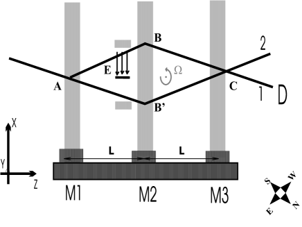
The principle of an electric polarizability measurement by atom interferometry ekstrom95 is to use a Mach-Zehnder atom interferometer in which the atomic beams can be separated by a septum and to apply an electric field on only one of the two atomic beams (see figure 1). For a given voltage applied on the capacitor creating the field, the polarizability phase shift of the atomic wave is given by:
| (1) |
Here is the atom velocity (for more details, see references miffre06a ; miffre06b ). An important point here is that the polarizability phase shift is proportional to and we will write
| (2) |
where is the phase shift for the atomic beam mean velocity defined below. We may note that the proportionality is the result of a first order perturbation calculation, valid if the ratio of the polarizability energy term to the atom kinetic energy (i.e. the ratio ) is considerably smaller than unity. In the experiments with thermal atoms ekstrom95 ; miffre06a ; miffre06b , this ratio is typically of the order of and this approximation is excellent.
Finally, the velocity dependence of the phase shift coupled to the velocity dispersion of the atomic beam induces a rapid reduction of the fringe visibility when the applied phase shift increases: as discussed in roberts04 , this effect limits the maximum measurable phase shift and ultimately the precision of the polarizability measurement.
III Sagnac effect
Atom interferometers are extremely sensitive to inertial effects and in particular to rotation of the setup, through Sagnac effect overhauser74 ; collela75 ; anandan77 ; werner79 ; riehle91 . Several gyrometers based on atom interferometry have been developed riehle91 ; lenef97 ; gustavson97 ; gustavson00 ; canuel06 and an extremely high sensitivity has been achieved gustavson00 . The Sagnac phase shift due to a rotation of the setup is given by:
| (3) |
Here, is the grating wave vector ( in the case of laser diffraction by a laser with a wave vector ); is the -component of the angular velocity of the laboratory frame with respect to a Galilean frame (the -axis being perpendicular to the plane of the atom trajectory, see figure 1); finally is the distance between consecutive gratings. In our experiment, the mean value of is due to the Earth rotation, while the seismic and laboratory vibrations induce rapid fluctuations of . The main effect of these fluctuations is to induce a phase noise which reduces the fringe visibility miffre06 ; jacquey 06 . With a period equal to the sidereal day, rad/s at the laboratory latitude , m-1 and m, the calculated Sagnac phase shift is given by:
IV Reanalysis of our experimental signals
As the phase shifts and are velocity dependent, both in , we must describe the velocity distribution of the atomic beam. As in references miffre06a ; miffre06b , we will use:
| (5) |
This equation is a simplified form of the velocity distribution of supersonic beams beijerinck83 ; haberland85 , with , the parallel speed ratio, defined such that where is the RMS about the mean velocity. In fact, is not the velocity distribution of the incident beam but the velocity distribution of the atoms contributing to the fringe signal i.e. it is the product of the velocity distribution of the incident beam by the transmission of the interferometer. This transmission is a function of the atom velocity, in particular because of the use of Bragg diffraction. Noting , the interferometer signal is given by:
| (6) | |||||
is a phase shift function of the standing wave positions, which serves to observe interference fringes and which is independent of the atom velocity. Equation (6) defines the observed visibility and the observed phase shift . These two averages are non linear, so that:
| (7) |
As a consequence, after taking the average, the polarizability and Sagnac phase shifts are not exactly additive. To measure the effect of an applied voltage , we make two measurements of the fringe phase, one with and one with and the difference provides our measurement of the polarizability phase shift given by:
| (8) |
As the electric field was applied on the ABC beam of the interferometer (see figure 1), one can verify that the polarizability and Sagnac phase shifts have opposite signs. We use equations (5,6,8) to fit our data with only two adjustable parameters, the parallel speed ratio and the ratio . The phase shift and visibility data are treated in a single fit and we get:
| (9) | |||||
| (10) |
In our initial fit neglecting the Sagnac effect miffre06a ; miffre06b , the parallel speed ratio was found equal to and this overestimation can be explained: the Sagnac and polarizability phase shifts being of opposite signs, the visibility decay is delayed by the existence of the Sagnac phase shift. This delay induced the initial fit toward a velocity dispersion smaller than its actual value.
The value is only slightly modified with respect to its previous value equal to . This is not surprising because the effect is very indirect, through the non-linear character of the average defined by equation (6). Our new value of the polarizability of 7Li is:
| (11) |
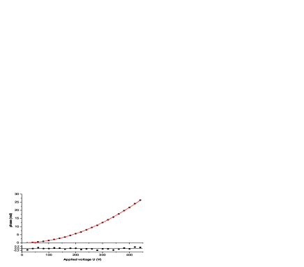
The % correction is considerably smaller than the % final error bar dominated by the uncertainty on the mean velocity . Figures 2 and 3 show the agreement between the data points and their fits. On the visibility data, the improvement is noticeable, especially when the measured phase shifts are smaller than rad.

V The use of a Sagnac counterphase for dispersion compensation
The fact that the polarizability phase shift is proportional to limits the accuracy of the measurement for three main reasons:
-
•
the visibility decreases rapidly when the mean phase shift increases and for sufficiently large phase shifts, the phase sensitivity is too small to be useful. T. D. Roberts et al. roberts04 have made a quantitative analysis of this effect, with an evaluation of the optimum phase shift in the case of a dependence of the phase shift with the velocity .
- •
-
•
finally, the mean velocity is difficult to determine with great accuracy, especially because the incident beam mean velocity is slightly modified by the velocity dependent transmission of the interferometer.
T. D. Roberts et al. proposed to compensate the polarizability phase shift by an engineered counterphase. To produce this counterphase, two time dependent phase shifts were applied at two points separated by a distance along the atom path in the interferometer. The counterphase is thus given by:
| (12) |
We will not reproduce the discussion of T. D. Roberts et al. to which we refer the reader. However, we point out, that in addition to the velocity dependence due to the term, there is a direct velocity dependence in of and due to the fact that these phase shifts are produced by applying an electric field gradient on the atomic beams inside the interferometer. This supplementary velocity dependence, which was not discussed in reference roberts04 , complicates the use of this counterphase, and we note that a high accuracy use of this technique remains to be demonstrated
VI The use of Sagnac phase shift for dispersion compensation
The observation presented in this paper suggests that one may use the Sagnac phase shift as a counterphase to compensate the polarisability phase shift. As both phase shifts are proportional to , the compensation should be exact and the only problem is to find a practical way of creating a large Sagnac phase shift.
If we move the mirrors of the first and/or third standing waves in opposite directions, these motions will exactly mimick a rotation of the interferometer. If the velocity of the mirrors and are respectively and , the induced phase shift is given by schmiedmayer97 :
| (13) |
This idea seems nice, especially as piezo-actuators with capacitive displacement sensors are available, with an uncertainty on the displacement smaller than nanometer. For a phase shift radians, the needed velocities are quite large m/s, which can be sustained only during about s if the displacement is limited to micrometers. The mirrors should be moved forward and backward with a few millisecond period. This rapid motion will perturb the interferometer and we think that this technique is not practically feasible.
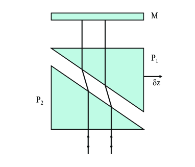
However, what we need is to change the positions of the nodes and anti-nodes of the laser standing waves and a two-prism arrangement as schematically represented in figure 4 can do the same effect. A displacement of the prism is equivalent to a change of the mirror position given by:
| (14) |
where and are the incidence and refraction angles of the laser beam on the prism hypotenuse. The final form assumes Brewster incidence as drawn on figure 4 (i.e. where is the index of refraction of the prism). With fused silica (), the ratio is close to and such an arrangement can replace a mirror displacement of several millimeters. It thus seems feasible to produce a Sagnac type phase shift of the order of radians during a time period of the order of second. Commercially available translation stages with interferometric control of the position can provide a very stable prism velocity which is needed because any velocity fluctuation will induce a phase noise.
The prism motion will induce a large Sagnac counterphase and the measurement will give . We must tune the Sagnac phase till is very small and then its value is, with a good approximation, the value for the mean velocity :
| (15) |
If the phase is very small, a low accuracy on is sufficient for an accurate measurement of the polarizability . This measurement will require an accurate measurement of the quantity . The laser wave vector is easily measured with a very high accuracy and it is possible to measure the velocity and/or with a high accuracy by optical interferometry (the laser standing waves used for diffraction can be used in Michelson interferometers for this measurement). The distance between laser standing waves may be difficult to measure with an accuracy better than about , because, as shown by C.J. Bordé borde04 and Ch. Antoine antoine04 ; antoine06 , the exact value of the distance is not exactly equal to the physical distance between the laser standing waves but its value depends on the diffraction regime and laser beam parameters.
Another technique to create a Sagnac type counter phase is to use laser Raman diffraction. This diffraction process, which is most commonly used in cold atom interferometers, has also been used by T. L. Gustavson et al. in their thermal atom gyrometer gustavson97 ; gustavson00 . With Raman diffraction, the phase of the interferometer signal can be modified by changing the frequency difference of the Raman laser beams. A Sagnac phase can be mimicked by applying opposite frequency offsets to the Raman beams used for the first and third diffraction events. T. L. Gustavson et al. gustavson00 have shown that this phase shift is proportional to and they used it to compensate the Sagnac phase shift. Such an electronic compensation can be used to compensate a very large polarizability phase shift.
VII Conclusion
In this paper, we have reanalyzed our measurement of the electric polarizability of lithium atom by atom interferometry and this reanalysis has taken into account the Sagnac phase shift due to Earth rotation, an effect which was ignored in our first analysis. The new value of the lithium electric polarizability differs only slightly (by %) from our previous value, well within our % error bar. However, the fit to the visibility data is improved and the deduced value of the parallel speed ratio is noticeably different.
The polarizability phase shift and the Sagnac phase shift have the same dependence with the atom velocity and this remark suggests that the Sagnac phase shift can be used to compensate the polarizability phase shift. The idea of compensating the polarizability phase shift by a counterphase was initially developed and demonstrated by T. D. Roberts et al. roberts04 and this technique should give access to high accuracy measurements of electric polarizability. In the experiment of T. D. Roberts et al., the counterphase had not exactly the same velocity dependence and this effect limits the possible accuracy. With a Sagnac phase shift as a counterphase, the compensation should be exact and the polarizability measurement will be replaced by a measurement of mirror velocity. Furthermore, if the interferometer uses Raman diffraction, the Sagnac phase can be mimicked by laser frequency offsets, which are even simpler to measure. In both cases, the size of the interferometer plays a role and its exact value will depend on the diffraction regime. The test of these compensation schemes require substantial modifications of our atom interferometer so that they cannot be done immediately but we expect to do so in a near future.
VIII Acknowledgements
The Toulouse group thanks CNRS department MPPU for its support, Région Midi-Pyrénées for a 2005-2006 PACA-MIP network and ANR for Grant ANR-05-BLAN-0094. AC thanks NSF for Grant No. PHY-0653623.
References
- (1) A. Miffre, M. Jacquey, M. Büchner, G. Trénec and J. Vigué, Phys. Rev. A 73, 011603(R) (2006)
- (2) A. Miffre, M. Jacquey, M. Büchner, G. Trénec and J. Vigué, Eur. Phys. J. D. 38, 353 (2006)
- (3) C. R. Ekstrom, J. Schmiedmayer, M. S. Chapman, T. D. Hammond and D. E. Pritchard, Phys. Rev. A 51, 3883 (1995)
- (4) T. D. Roberts, A. D. Cronin, M. V. Tiberg and D. E. Pritchard, Phys. Rev. Lett. 92, 060405 (2004)
- (5) A. W. Overhauser and R. Collela, Phys. Rev. Lett. 33, 1237 (1974)
- (6) R. Collela, A. W. Overhauser and S. A. Werner, Phys. Rev. Lett. 34, 1472 (1975)
- (7) J. Anandan, Phys. Rev. D 15, 1448 (1977)
- (8) S. A. Werner, J.-L. Stauidenmann and R. Collela, Phys. Rev. Lett. 42, 1103 (1979)
- (9) F. Riehle, Th. Kisters, A. Witte, J. Helmcke and Ch. J. Bord , Phys. Rev. Lett. 67, 177 (1991)
- (10) A. Lenef, T. D. Hammond, E. T. Smith, M. S. Chapman, R. A. Rubenstein and D. E. Pritchard, Phys. Rev. Lett. 78, 760 (1997)
- (11) T. L. Gustavson, P. Bouyer and M. A. Kasevich, Phys. Rev. Lett. 78, 2046 (1997)
- (12) T. L. Gustavson, A. Landragin and M. A. Kasevich, Class. Quantum Grav. 17, 2385 (2000)
- (13) B. Canuel, F. Leduc, D. Holleville, A. Gauguet, J. Fils, A. Virdis, A. Clairon, N. Dimarcq, Ch. J. Bordé, A. Landragin and P. Bouyer, Phys. Rev. Lett. 97, 010402 (2006)
- (14) A. Miffre, M. Jacquey, M. Büchner, G. Trénec and J. Vigué, Appl Phys. B 84, 617 (2006)
- (15) M. Jacquey, A. Miffre, M. Büchner, G. Trénec and J. Vigué, Europhysics Letters 75, 688-694 (2006)
- (16) H. C. W. Beijerinck, G. H. Kaashoek, J. P. M. Beijers and M. J. Verheijen, Physica 121 C, 425 (1983)
- (17) H. Haberland, U. Buck and M. Tolle, Rev. Sci. Instrum. 56, 1712 (1985)
- (18) J. Schmiedmayer, M. S. Chapman, C. R. Ekstrom, T. D. Hammond, D. A. Kokorowski, A. Lenef, R. A Rubenstein, E. T. Smith and D. E. Pritchard in Atom interferometry edited by P. R. Berman (Academic Press, 1997), p. 1
- (19) Ch. J. Bordé, General Relativity and Gravitation, 36, 475 (2004)
- (20) C. Antoine, PhD thesis, Université Paris 6, http://tel.archives-ouvertes.fr/docs/00/04/75/84/PDF /tel-00007967.pdf
- (21) C. Antoine, Appl. Phys. B 84, 585 (2006)