Degrees of Freedom of the User MIMO Interference Channel
Abstract
We provide innerbound and outerbound for the total number of degrees of freedom of the user multiple input multiple output (MIMO) Gaussian interference channel with antennas at each transmitter and antennas at each receiver if the channel coefficients are time-varying and drawn from a continuous distribution. The bounds are tight when the ratio is equal to an integer. For this case, we show that the total number of degrees of freedom is equal to if and if . Achievability is based on interference alignment. We also provide examples where using interference alignment combined with zero forcing can achieve more degrees of freedom than merely zero forcing for some MIMO interference channels with constant channel coefficients.
I introduction
Interference management is an important problem in wireless system design. Researchers have been exploring the capacity characterization of the Gaussian interference channel from a information theoretic perspective for more than thirty years. Several innerbounds and outerbounds of the capacity region for the two user Gaussian interference channel with single antenna nodes are determined [1, 2, 3, 4, 5, 6, 7, 8, 9, 10]. However, the capacity region of the Gaussian interference channel remains an open problem in general. Interference channels with multiple-antenna nodes are studied in [11, 12, 13].
I-A Motivating Example
In [13], the authors study the achievable rate region of the multiple input single output (MISO) interference channel obtained by treating interference as noise. They parameterize the Pareto boundary of the MISO Gaussian interference channel for arbitrary number of users and antennas at the transmitter as long as the number of antennas is larger than the number of users. For 2 user case, they show that the optimal beamforming directions are a linear combination of maximum ratio transmission vectors and the zero forcing vectors. However, for the case when the number of antennas is less than that of users, the optimal beamforming direction is not known. Intuitively, this is because when the number of antennas is less than that of users, it is not possible for each user to choose beamforming vectors to ensure no interference is created at all other users. The same problem is evident when we study this channel from a degrees of freedom 111If the sum capacity can be expressed as then we say that the channel has degrees of freedom. perspective. For the 2 user MISO interference channel with 2 transmit antennas and a single receive antenna, it is easy to see 2 degrees of freedom can be achieved if each user chooses zero forcing beamforming vector so that no interference is created at the other user. This is also the maximum number of degrees of freedom of this channel. However, for 3 user MISO interference channel with two antennas at each transmitter, it is not possible for each user to choose beamforming vectors so that no interference is created at all other users. As a result, only 2 degrees of freedom can be achieved by zero forcing. Can we do better than merely zero forcing? What is the total number of degrees of freedom of the 3 user MISO interference channel with 2 antennas at each transmitter? In general, what is the total number of degrees of freedom of the user MIMO interference channel? These are the questions that we explore in this paper.
Before we answer the above questions, let us first review the results on the degrees of freedom for the user single input single output (SISO) Gaussian interference channel. If , it is well known the degrees of freedom for this point to point channel is 1. If , it is shown that this channel has only 1 degrees of freedom [14]. In other words, each user can achieve degrees of freedom simultaneously. For , it is surprising that every user is still able to achieve degrees of freedom no matter how large is, if the channel coefficients are time-varying or frequency selective and drawn from a continuous distribution [16]. The achievable scheme is based on interference alignment combined with zero forcing.
For the MISO interference channel we find a similar characterization of the degrees of freedom. For example, the degrees of freedom for the 3 user MISO interference channel with 2 antennas at each transmitter is only 2 which is the same as that for the 2 user case. In other words, every user can achieve degrees of freedom simultaneously. For , every user is still able to achieve degrees of freedom regardless of if the channel coefficients are time-varying or frequency selective and drawn from a continuous distribution. The achievable scheme is based on interference alignment on the single input multiple output (SIMO) interference channel for simplicity. If interference alignment is achieved on the SIMO channel it can also be achieved on the MISO channel, due to a reciprocity of alignment [19]. Interestingly, the interference alignment scheme is different from all prior schemes. All prior interference alignment schemes [16] (including the ones for the channel [17, 18]) explicitly achieve one-to-one alignment of signal vectors, i.e., to minimize the dimension of the space spanned by interference signal vectors, one signal vector from an interferer and one signal vector from another interferer are aligned along the same dimension at the desired receivers. For example, consider 3 user SISO interference channel with 2 symbol extension or 3 user MIMO interference channel where each node has 2 antennas. We need to choose beamforming vectors and at Transmitter 2 and 3, respectively so that they cast overlapping shadow at Receiver 1, i.e.,
where and are channel matrices from Transmitter 2 and 3 to Receiver 1, respectively. However, such an alignment is not feasible on the SIMO channel. Notice that the solution to the condition mentioned above exists only when the range of the two channel matrices has intersection. The channel matrix for 2 symbol extension SIMO channel with 2 antennas at each receiver is . The range of two such channel matrices has null intersection with probability one if the channel coefficients are drawn from a continuous distribution. Thus, one-to-one interference alignment does not directly work for SIMO channel. Instead, interference from one interferer can only be aligned within the union of the spaces spanned by the interference vectors from other interferers where is the number of antennas at each receiver.
I-B Overview of Results
In this paper we study the degrees of freedom of the user MIMO Gaussian interference channel with antennas at each transmitter and antennas at each receiver. We provide both the innerbound (achievability) and outerbound (converse) of the total number of degrees of freedom for this channel. We show that degrees of freedom can be achieved if and degrees of freedom can be achieved if where . The total number of degrees of freedom is bounded above by if and if . The bounds are tight when the ratio is equal to an integer which includes MISO and SIMO interference channel as special cases. The result indicates when every user can achieve degrees of freedom which is the same as what one can achieve without interference. When every user can achieve a fraction of the degrees of freedom that one can achieve in the absence of all interference. In other words, if , then there is no loss of degrees of freedom for each user with interference. If , every user only loses a fraction of the degrees of freedom that can be achieved without interference. In the second part of this paper we study the achievable degrees of freedom based on interference alignment scheme for the user MIMO interference channel with antennas at each transmitter and , antennas at each receiver and constant channel coefficients, i.e. in the absence of time variation. We show that for this channel degrees of freedom can be achieved without symbol extension. When and hence , degrees of freedom per orthogonal dimension can be achieved with finite symbol extension. Since only degrees of freedom can be achieved using zero forcing, these results provide interesting examples where using interference alignment scheme can achieve more degrees of freedom than merely zero forcing.
II system model
The user MIMO interference channel is comprised of transmitters and receivers. Each transmitter has antennas and each receiver has antennas. The channel output at the receiver over the time slot is characterized by the following input-output relationship:
where, is the user index, is the time slot index, is the output signal vector of the receiver, is the input signal vector of the transmitter, is the channel matrix from transmitter to receiver over the time slot and is additive white Gaussian noise (AWGN) vector at the receiver. We assume all noise terms are i.i.d zero mean complex Gaussian with unit variance. We assume that all channel coefficient values are drawn i.i.d. from a continuous distribution and the absolute value of all the channel coefficients is bounded between a non-zero minimum value and a finite maximum value. The channel coefficient values vary at every channel use. Perfect knowledge of all channel coefficients is available to all transmitters and receivers.
Transmitters have independent messages intended for receivers , respectively. The total power across all transmitters is assumed to be equal to . We indicate the size of the message set by . For codewords spanning channel uses, the rates are achievable if the probability of error for all messages can be simultaneously made arbitrarily small by choosing an appropriately large . The capacity region of the user MIMO interference channel is the set of all achievable rate tuples .
We define the spatial degrees of freedom as:
| (1) |
where is the sum capacity at SNR .
III Outerbound on the degrees of freedom for the user MIMO interference channel
We provide an outerbound on the degrees of freedom for the user MIMO Gaussian interference channel in this section. Note that the converse holds for both time-varying and constant (non-zero) channel coefficients, i.e., time variations are not required. We present the result in the following theorem:
Theorem 1
For the user MIMO Gaussian interference channel with antennas at each transmitter and antennas at each receiver, the total number of degrees of freedom is bounded above by if and if where , i.e.
where 1(.) is the indicator function and represents the individual degrees of freedom achieved by user .
Proof:
1) : It is well known that the degrees of freedom of a
single user MIMO Gaussian channel with transmit antennas and
receive anteanns is equal to . Thus, for the user
MIMO Gaussian interference channel with the same antenna deployment,
the degrees of freedom cannot be more than , i.e .
2) : Consider the user MIMO interference channel with
antennas at the transmitter and receiver respectively. If we
allow full cooperation among transmitters and full cooperation
among their corresponding receivers, then it is equivalent to the
two user MIMO interference channel with , (respectively)
antennas at transmitters and , antennas at their
corresponding receivers. In [15], it is shown that
the degrees of freedom for a two user MIMO Gaussian interference
channel with , antennas at transmitter , and
, antennas at their corresponding receivers is
min{, , max(,), max(,)}.
From this result, the degrees of freedom for the two user MIMO
interference channel with , antennas at the transmitters and
, at their corresponding receivers is . Since
allowing transmitters and receivers to cooperate does not hurt the
capacity, the degrees of freedom of the original user
interference channel is no more than . For user
case, picking any users among users gives an outerbound:
| (2) |
Adding up all such inequalities, we get the outerbound of the user MIMO interference channel:
| (3) |
∎
IV Innerbound on the degrees of freedom for the user MIMO interference channel
To derive the innerbound on the degrees of freedom for the user MIMO Gaussian interference channel, we first obtain the achievable degrees of freedom for the user SIMO interference channel with antennas at each receiver. The innerbound on the degrees of freedom of the user MIMO interference channel follows directly from the results of the SIMO interference channel. The corresponding input-output relationship of the user SIMO interference channel is:
where , , , represent the channel output at receiver , the channel input from transmitter , the channel vector from transmitter to receiver and the AWGN vector at receiver over the time slot respectively.
We start with the problem mentioned in the introduction. For the 3 user SIMO Gaussian interference channel with 2 receive antennas, 2 degrees of freedom can be achieved using zero forcing. From the converse result in the last section, we cannot achieve more than 2 degrees of freedom on this channel. Therefore, the maximum number of degrees of freedom for this channel is 2. For the 4 user case, the converse result indicates that this channel cannot achieve more than degrees of freedom. Can we achieve this outerbound? Interestingly, using interference alignment scheme based on beamforming over multiple symbol extensions of the original channel, we are able to approach arbitrarily close to the outerbound. Consider the symbol extension of the channel for any arbitrary . Then, we effectively have a channel with a block diagonal structure. In order for each user to get exactly degrees of freedom per channel use and hence degrees of freedom on the symbol extension channel, each receiver with a total of dimensional signal space should partition its signal space into two disjoint subspaces, one of which has dimension for the desired signals and the other has dimension for the interference signals. While such an alignment would exactly achieve the outerbound, it appears to be infeasible in general. But if we allow user 4 to achieve only degrees of freedom over the extension channel where , then it is possible for user 1, 2, 3 to achieve exactly degrees of freedom simultaneously for a total of degrees of freedom over the symbol extension channel. Hence, degrees of freedom per channel use can be achieved. As , . Therefore, we can achieve arbitrarily close to the outerbound . Next we present a detailed description of the interference-alignment scheme for the 4 user SIMO channel with 2 antennas at each receiver.
In the extended channel, Transmitter sends message to Receiver in the form of independently encoded steams along the same set of beamforming vectors , each of dimension , so that we have
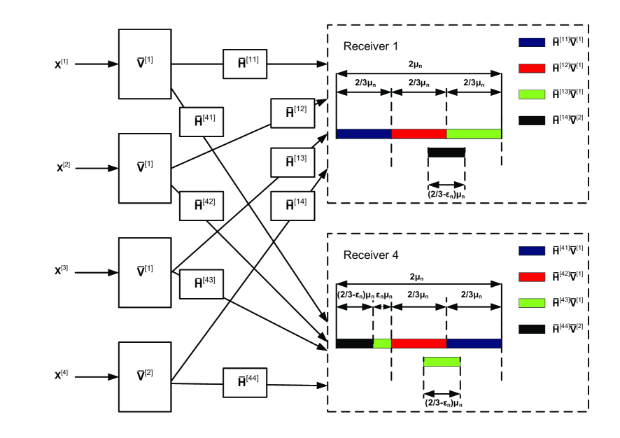
where is a matrix and is a column vector. Transmitter 4 sends message to Receiver 4 in the form of independently encoded streams along the beamforming vectors so that
where is a matrix and is a column vector. Therefore, the received signal at Receiver is
where is the matrix representing the extension of the original channel matrix, i.e.
where is a vector with zero entries. Similarly, and represent the symbol extension of the and respectively. The interference alignment scheme is shown in Fig. 1. At Receiver 1, the interference from Transmitter 2 and Transmitter 3 cannot be aligned with each other because the subspaces spanned by the columns of and have null intersection with probability one. Thus, the interference vectors from Transmitter 2, i.e. columns of and interference vectors from Transmitter 3, i.e. columns of together span a dimensional subspace in the dimensional signal space at Receiver 1. In order for Receiver 1 to get a dimensional interference-free signal space, we need to align the space spanned by the interference vectors from Transmitter 4, i.e. the range of within the space spanned by the interference vectors from Transmitter 2 and 3. Note that we cannot align the interference from Transmitter 4 within the space spanned by the interference vectors from Transmitter 2 only or Transmitter 3 only. Because the subspaces spanned by the columns of and or the subspaces spanned by the columns of and have null intersection with probability one. Mathematically, we have
| (5) |
where means the space spanned by the columns of matrix . This condition can be expressed equivalently as
where denotes a matrix with zero entries. Note that is a matrix with full rank almost surely. Therefore, the last equation is equivalent to
| (8) |
where is a matrix which can be written in a block matrix form:
where and are matrices. Therefore, (8) can be expressed alternatively as
| (13) |
This condition can be satisfied if
| (16) |
where means that the set of column vectors of matrix is a subset of the set of column vectors of matrix .
Similarly, at Receiver 2, the interference vectors from Transmitter 4 are aligned within the space spanned by the interference vectors from Transmitter 1 and 3, i.e.,
| (17) |
This condition can be satisfied if
| (20) |
where
At Receiver 3, the interference vectors from Transmitter 4 are aligned within the space spanned by the interference vectors from Transmitter 1 and 2, i.e.
| (21) |
This condition can be satisfied if
| (24) |
where
Now, let us consider Receiver 4. As shown in Fig. 1, to get a interference free dimensional signal space, the dimension of the space spanned by the interference vectors has to be less than or equal to . To achieve this, we align the space spanned by vectors of the interference vectors from Transmitter 3 within the space spanned by the interference from Transmitter 1 and 2. Since is a matrix, we can write it as where and are and matrices, respectively. We assume the space spanned by the columns of is aligned within the space spanned by the interference from Transmitter 1 and 2, i.e.,
| (25) |
From equation (16), we have
This implies that columns of are equal to the columns of . Without loss of generality, we assume that . Thus, (25) can be written as
Note that is a matrix and can be written in a block matrix form:
where each block is a matrix. Then, the above equation can be expressed as
The above condition can be satisfied if
| (30) |
Therefore, we need to design and to satisfy conditions (16), (20), (24), (30). Let be a column vector . We need to choose column vectors for and column vectors for . The sets of column vectors of and are chosen to be equal to the sets and where
For example, when , the set consists of two
elements, i.e.,
. The set
consists of column vectors in the form
where takes values ; takes
values . Note that the above construction requires the
commutative property of multiplication of matrices
. Therefore, it requires to
be diagonal matrices. We provide the proof to show this is true in
Appendix A. In order for each user to decode its
desired message by zero forcing the interference, it is required
that the desired signal vectors are linearly independent of the
interference vectors. We also show this is true in Appendix
A.
Remark: Note that for the user Gaussian interference channel with single antenna nodes[16] and user channel [18], we need to construct two precoding matrices and to satisfy several such conditions . Here, we use the same precoding matrix for Transmitter 1, 2, 3 so that we need to design two precoding matrices and to satisfy similar conditions . Therefore, we use the same method in [16] and [18] to design and here.
We present the general result for the achievable degrees of freedom of the SIMO Gaussian interference channel in the following theorem.
Theorem 2
For the user SIMO Gaussian interference channel with a single antenna at each transmitter and antennas at each receiver, a total of degrees of freedom per orthogonal time dimension can be achieved.
Proof:
We provide the proof in Appendix A. ∎
Next, we present the innerbound on the degrees of freedom for the user MIMO Gaussian interference channel in the following theorem:
Theorem 3
For the time-varying user MIMO Gaussian interference channel with channel coefficients drawn from a continuous distribution and antennas at each transmitter and antennas at each receiver, degrees of freedom can be achieved if and degrees of freedom can be achieved if where , i.e.
where 1(.) is the indicator function and represents the individual degrees of freedom achieved by user .
Proof:
When , the achievable scheme is based on beamforming and
zero forcing. There is a reciprocity of such scheme discussed in
[18]. It is shown that the degrees of freedom is
unaffected if all transmitters and receivers are switched. For
example, the degrees of freedom of the user MISO interference
channel with 2 transmit antennas and a single receive antenna is the
same as that of the 2 user SIMO interference channel with a single
transmit antenna and 2 receive antennas. When , the achievable
scheme is based on interference alignment. There is a reciprocity of
alignment which shows that if interference alignment is feasible on
the original channel then it is also feasible on the reciprocal
channel [19]. Therefore, without loss
of generality, we assume that the number of transmit antennas is
less than or equal to that of receive antennas, i.e. . As
a result, we need to show that degrees of freedom can be
achieved if and degrees of freedom can
be achieved if where
. The case when is solved in [16]. Therefore, we only consider the cases when here.
1) : Each transmitter sends independent data streams
along beamforming vectors. Each receiver gets interference free
streams by zero forcing the interference from unintended
transmitters. As a result, each user can achieve degrees of
freedom for a total of degrees of freedom.
2) : When , by discarding one user, we have a user
interference channel. degrees of freedom can be achieved on
this channel using the achievable scheme described above. When
, first we get antennas receive nodes by discarding
antennas at each receiver. Then, suppose we view each user
with antennas at the transmitter and antennas at the
receiver as different users each of which has a single transmit
antenna and receive antennas. Then, instead of a user MIMO
interference channel we obtain a user SIMO interference channel
with antennas at each receiver. By the result of Theorem
2, degrees of freedom can be achieved
on this interference channel. Thus, we can also achieve
degrees of freedom on the user MIMO
interference channel with time-varying channel coefficients.
∎
Finally, we show that the innerbound and outerbound are tight when the ratio is equal to an integer. We present the result in the following corollary.
Corollary 1
For the time-varying user MIMO Gaussian interference channel with transmit antennas and receive antennas, the total number of degrees of freedom is equal to if and if when is equal to an integer, i.e.
Proof:
The proof is obtained by directly verifying that the innerbound and outerbound match when the ratio is equal to an integer. When , the innerbound and outerbound always match which is . When , the innerbound and outerbound match when which implies that . In other words, when either the number of transmit antennas is an integer multiple of that of receive antennas or vice versa, the total number of degrees of freedom is equal to . ∎
Remark: For the user MIMO Gaussian interference channel with antennas at the transmitter and the receiver respectively, if where then the total number of degrees of freedom is . This result can be extended to the same channel with constant channel coefficients.
Remark: If , then Corollary 1 shows that the total number of degrees of freedom of the user SIMO Gaussian interference channel with receive antennas or the user MISO Gaussian interference channel with transmit antennas is equal to .
V Achievable Degrees of Freedom for the MIMO interference channel with constant channel coefficients
Note that the converse results and the results of the achievable degrees of freedom based on merely zero forcing in previous sections are also applicable to the same channel with constant channel coefficients. The results of the achievable degrees of freedom based on interference alignment are obtained under the assumption that the channel coefficients are time-varying. It is not known if the results can be extended to the same channel with constant channel coefficients. Because the construction of precoding matrices and requires commutative property of multiplication of diagonal matrices . But for the MIMO scenarios, those matrices are not diagoal and commutative property cannot be exploited. In fact, the degrees of freedom for the interference channel with constant channel coefficients remains an open problem for more than 2 users. One known scenario is the 3 user MIMO Gaussian interference channel with antennas at each node. In [16], it is shown that the total number of degrees of freedom is . The achievable scheme is based on interference alignment on signal vectors. In [20], the first known example of a user Gaussian interference channel with single antenna nodes and constant channel coefficients are provided to achieve the outerbound on the degrees of freedom. The achievable scheme is based on interference alignment on signal levels rather than signal vectors. In this section, we will provide examples where interference alignment combined with zero forcing can achieve more degrees of freedom than merely zero-forcing for some MIMO Gaussian interference channels with constant channel coefficients. More general results are provided in Appendix B.
Example 1: Consider the 4 user MIMO Gaussian interference channel with 4 antennas at each transmitter and 8 antennas at each receiver. Note that for the 3 user MIMO interference channel with the same antenna deployment, the total number of degrees of freedom is 8. Also, for the 4 user case, only 8 degrees of freedom can be achieved by merely zero forcing. However, we will show that using interference alignment combined with zero forcing, 9 degrees of freedom can be achieved on this interference channel without channel extension. In other words, the 4 user MIMO interference channel with 4, 8 antennas at each transmitter and receiver respectively can achieve more degrees of freedom than the 3 user interference channel with the same antenna deployment. Besides, more degrees of freedom can be achieved on this 4 user interference channel by using interference alignment combined with zero forcing than merely zero forcing. Next, we show that user can achieve degrees of freedom and user 4 can achieve degrees of freedom resulting in a total of 9 degrees of freedom achieved on this channel. Transmitter sends message to Receiver using independently encoded streams along vectors , i.e.,
where and . The signal at Receiver can be written as
In order for each receiver to decode its message by zero forcing the interference signals, the dimension of the space spanned by the interference signal vectors has to be less than or equal to . Since there are interference vectors at receiver , we need to align interference signal vector at each receiver. This can be achieved by if one interference vector lies in the space spanned by other interference vectors at each receiver. Mathematically, we choose the following alignments
| (33) | |||||
| (38) |
| (41) | |||||
| (46) |
| (49) | |||||
| (54) | |||||
| (57) | |||||
| (62) |
where is an matrix which can be written in a block matrix form:
| (63) |
where and are matrices. To satisfy the conditions (38), (46), (54), (62), we let
Notice once is chosen, all other vectors can be solved from the above equations. To solve , we have
where is an eigenvector of matrix . Note that the above construction only specifies and . The remaining can be picked randomly according to a continuous distribution so that all columns of are linearly independent.
Through interference alignment, we ensure that the interference vectors span a small enough signal space. We need to verify that the desired signal vectors, i.e., are linearly independent of interference vectors so that each receiver can decode its message using zero forcing. Notice that the direct channel matrices do not appear in the interference alignment equations, undergoes an independent linear transformation by multiplying . Therefore, at each receiver the desired signal vectors are linearly independent of the interference signal vectors with probability one. As a result, user can achieve degrees of freedom and a total of 9 degrees of freedom can be achieved.
Example 2: Consider the 4 user MIMO Gaussian interference channel with 2 antennas at each transmitter and 4 antennas at each receiver. We show that 9 degrees of freedom can be achieved on the 2-symbol extension of the original channel and hence 4 degrees of freedom per channel use can be achieved. Since only 4 degrees of freedom can be achieved using merely zero forcing, more degrees of freedom is achieved using interference alignment scheme. Note that although we have equivalently a 4 user interference channel with channel on the 2-symbol extension channel, we cannot use the same achievable scheme used in Example 1 due to the block diagonal structure of the extension channel matrix. Consider 2-symbol extension of the channel. The channel input-output relationship is
where the overbar notation represents the 2-symbol extensions so that
where and are and vectors respectively, and
where is the channel matrix. We assign and degrees of freedom to message respectively for a total 9 degrees of freedom over the 2-symbol extension channel. Transmitter sends message in the form of independently encoded streams along the direction vectors , each of dimension , so that we have:
where and are and matrices respectively. In order to get interference free dimension at Receiver , we need to align 1 interference vector at each receiver. This can be achieved if one interference vector lies in the space spanned by other interference vectors at each receiver. Mathematically, we choose the following alignments:
| (66) | |||
| (69) | |||
| (72) | |||
| (75) |
where is the matrix which can be written in a block matrix form:
| (76) |
The above equations can be satisfied if
| (85) |
Notice that once we pick , all other vectors can be solved from above equations. can be chosen randomly according to a continuous distribution so that all vectors are linearly independent with probability one. Also, since all the vectors are chosen independently of the direct channel matrices and all entries of are not equal to zero almost surely, the desired signal vectors are linearly independent of the interference vectors at each receiver. As a result, Receiver can decode its message by zero forcing the interference to achieve degrees of freedom for a total of 9 degrees of freedom over the 2-symbol extension channel. Therefore, degrees of freedom per channel use can be achieved on the original channel.
VI conclusion
We investigate the degrees of freedom for the user MIMO Gaussian interference channel with antennas at each transmitter and receiver, respectively. The motivation of this work is the potential benefits of interference alignment scheme shown recently to achieve the capacity of certain wireless networks within . In this work, interference alignment scheme is also found to be optimal in achieving the degrees of freedom of the user MIMO Gaussian interference channel if the ratio is equal to an integer with time-varying channel coefficients drawn from a continuous distribution. We also explore the achievable degrees of freedom for the MIMO interference channel with constant channel coefficients using interference alignment combined with zero forcing. We provide some examples where using interference alignment can achieve more degrees of freedom than merely zero forcing.
Appendix A Proof of Theorem 2
Proof:
Let . We will develop a coding scheme based on interference alignment to achieve a total of degrees of freedom over a symbol extension of the original channel. Hence, a total of degrees of freedom per orthogonal dimension can be achieved for any arbitrary . Taking supremum over all proves the total number of degrees of freedom is equal to as desired. Specifically, over the extended channel, user achieves degrees of freedom and other user achieves degrees of freedom. As a result, user achieves degrees of freedom and user achieves degrees of freedom per channel use, i.e.
| (86) |
This implies that
| (87) |
In the extended channel, the signal vector at the user’s receiver can be expressed as
where is a column vector representing the symbol extension of the transmitted symbol , i.e.
Similarly, and represent symbol extensions of the and respectively. is a matrix representing the symbol extension of the channel, i.e.
| (92) |
where is the channel vector. Message () is encoded at Transmitter into independent streams , along the same set of vectors so that is
where is a column vector and is a dimensional matrix. Similarly, () is encoded at Transmitter into independent streams , along the same set of vectors so that
The received signal at the receiver can then be written as
We wish to design the direction vectors and so that signal spaces are aligned at receivers where they constitute interference while they are separable at receivers where they are desired. As a result, each receiver can decode its desired signal by zero forcing the interference signals.
First consider Receiver , . Every receiver needs a interference free dimension out of the dimensional signal space. Thus, the dimension of the signal space spanned by the interference signal vectors cannot be more than . Notice that all the interference vectors from Transmitter span a dimensional subspace in the dimensional signal space. Hence, we can align the interference signal vectors from Transmitter , within this dimensional subspace. Mathematically, we have
where represents the space spanned by the columns of matrix . The above equation can be expressed equivalently as
Notice that is a square matrix with full rank almost surely. Thus, the above equation can be expressed equivalently as
| (100) |
Note that is a matrix and can be written in a block matrix form:
| (101) |
where each block is a matrix. Then, (A) can be expressed equivalently as
The above condition can be satisfied if
| (102) |
where means that the set of column vectors of matrix is a subset of the set of column vectors of matrix .
Then consider Receiver , . To get a interference free dimension signal space, the dimension of the signal space spanned by the interference vectors cannot be more than at each receiver. This can be achieved if all interference vectors from Transmitter , and interference vectors from Transmitter are aligned within the signal space spanned by interference vectors from transmitter . We first consider aligning the interference from Transmitter . Mathematically, we choose the following alignments:
Notice that is a square matrix with full rank almost surely. Thus, the above equation can be expressed equivalently as
| (108) |
Note that is a matrix and can be written in a block matrix form:
where each block is a matrix. Then, (108) can be expressed as
The above condition can be satisfied if
| (109) |
Now consider aligning interference vectors from Transmitter at Receiver , . This can be achieved if the space spanned by columns of is aligned within the range of . Since is a matrix, we can write it as where and are and matrices, respectively. We assume the space spanned by the columns of is aligned within the space spanned by the interference from Transmitter 1, 2, …, . From equation (102), we have
This implies that columns of are equal to the columns of . Without loss of generality, we assume that . Thus, to satisfy the interference alignment requirement, we choose the following alignments:
Note that is a matrix and can be written in a block matrix form:
where each block is a matrix. Then, the above equation can be expressed as
The above condition can be satisfied if
| (112) |
Thus, interference alignment is ensured by choosing and to satisfy (102), (109), (112). Note that these conditions can be expressed as
| (113) |
where . Therefore, there are such equations. We need to choose column vectors for and column vectors for . Let be a column vector . The sets of column vectors of and are chosen to be equal to the sets and respectively where
| (114) |
| (115) |
Note that the above construction requires the commutative property of multiplication of matrices . Therefore, it requires to be diagonal matrices. Next, we will show this is true. We illustrate this for the case when and . Similar arguments can be applied to other cases. Notice that is a square matrix:
Then,
where is a row vector and
| (123) |
Recall
Thus,
| (125) |
Hence, are diagonal matrices with diagonal entries , .
Through interference alignment, we ensure that the dimension of the interference is small enough. Now we need to verify that the desired signal vectors are linearly independent of the interference vectors so that each receiver can separate the signal and interference signals. Consider Receiver 1. Since all interference vectors are aligned in the signal space spanned by interference from transmitter , it suffices to verify that columns of are linearly independent of columns of almost surely. Notice that the direct channel matrix does not appear in the interference alignment equations and is chosen independently of . Then, the desired signal undergoes an independent linear transformation by multiplying . Thus, columns of are linearly independent of columns of almost surely as long as all entries of are not equal to zero with probability one. If there are some entries of are equal to zero, then due to the block diagonal structure of the desired signal vectors are linearly dependent of the interference vectors. For example, consider three diagonal matrix , , whose entries are drawn according to a continuous distribution. is a vector whose entries depend on entries of , and are non-zero with probability one. Vectors and span a plane in the three dimensional space. Now vector undergoes a random linear transformation by multiplying . The probability that vector lies in that plan is zero. If has one zero entry, for example , then and are two dimensional vectors in the three dimensional vector space. Hence they are linearly dependent. Next we will verify all entries of and are nonzero with probability one through their construction from and . From (114), (115) and (125), it can be seen that each entry of and is a product of the power of some . To verify each entry of and is not equal to zero with probability one, we only need to verify is not equal to zero with probability one. Since each entry of is drawn from a continuous distribution, if and only if all entries of are equal to zero. However, is a row of the inverse of the square matrix. Thus, not all entries of are equal to zero with probability one. As a result, all entries of and are not equal to zero with probability one. To this end, we conclude that at Receiver 1 the desired signal vectors are linearly independent with the interference signal vectors.
Similar arguments can be applied at Receiver to show that the desired signal vectors are linearly independent of the interference vectors. Thus, each receiver can decode its desired streams using zero forcing. As a result, each user can achieve degrees of freedom per channel use for a total of degrees of freedom with probability one. ∎
Appendix B The achievable degrees of freedom of the MIMO Gaussian Interference channel with constant channel coefficients
In this appendix, we consider the achievable degrees of freedom for some MIMO Gaussian interference channels with constant channel coefficients. Specifically, we consider the user MIMO Gaussian interference channel where each transmitter has antennas and receiver has , antennas. The main results of this section are presented in the following theorems:
Theorem 4
For the user MIMO Gaussian interference channel where each transmitter has antennas and each receiver has , , antennas with constant channel coefficients, degrees of freedom can be achieved without channel extension.
Proof:
The achievable scheme is provided in the following part. ∎
Theorem 4 is interesting because it shows that when and hence , using interference alignment scheme combined with zero forcing can achieve more degrees of freedom than merely zero forcing. It also shows that the user MIMO interference channel with antennas at each transmitter and antennas at each receiver can achieve more degrees of freedom than user with the same antenna deployment when . For example, if , Theorem 4 shows that for the 4 user interference channel with and antennas at each transmitter and receiver respectively, degrees of freedom can be achieved using interference alignment. However, only degrees of freedom can be achieved using zero forcing. Thus, when , using interference alignment combined with zero forcing can achieve more degrees of freedom than merely zero forcing. Similarly, only degrees of freedom can be achieved on the 3 user interference channel with the same antenna deployment. Hence, when more degrees of freedom can be achieved on the 4 user interference channel. While Theorem 4 indicates that when using interference alignment combined with zero forcing may not achieve more degrees of freedom than zero forcing without channel extension, using interference alignment can achieve more degrees of freedom if we allow channel extension. We present the result in the following theorem:
Theorem 5
For the user MIMO interference channel where each transmitter has antennas and each receiver has , , antennas with constant channel coefficients, degrees of freedom per orthogonal dimension can be achieved with channel extension.
Proof:
The achievable scheme is provided in the following part. ∎
Theorem 5 shows that if we allow channel extension, more degrees of freedom can be achieved using interference alignment combined with zero forcing than merely zero forcing. For example, when , more degrees of freedom can be achieved using interference alignment.
B-A Proof of Theorem 4
When and hence , degrees of freedom can be achieved by zero forcing at each receiver. When , we provide an achievable scheme based on interference alignment to show that the user can achieve degrees of freedom where and .
Transmitter sends message to Receiver using independently encoded streams along vectors , i.e,
Then, the received signal is
In order for each receiver to decode its desired signal streams by zero forcing the interference, the dimension of the interference has to be less than or equal to . However, there are interference vectors at Receiver . Therefore, we need to align interference signal vectors at each receiver. This can be achieved if interference vectors are aligned within the space spanned by all other interference vectors. First, we write in the block matrix form:
where are dimensional matrices and is an dimensional matrix. At Receiver 1, we align the range of within the space spanned by other interference vectors:
| (130) |
Note that is a matrix and can be written in a block matrix form:
Then, condition (130) can be expressed equivalently as
This condition can be satisfied if
| (131) |
At Receiver 2, we align the range of within the space spanned by other interference vectors:
By similar arguments used at Receiver 1, this condition can be satisfied if
| (132) |
where
At Receiver , , we align the range of within the space spanned by other interference vectors:
By similar arguments used at Receiver 1, this condition can be satisfied if
where
At Receiver , we align the range of within the space spanned by other interference vectors:
This condition can be satisfied if
where
Notice once is chosen, all other vectors can be solved from the above equations. To solve , from (131), (132), we have
Hence, columns of can be chosen as
| (135) |
where are the eigenvectors of . Note that the above construction only specifies . The remaining vectors of can be chosen randomly according to a continuous distribution.
Through interference alignment, we ensure that the interference vectors span a small enough signal space. We need to verify that the desired signal vectors, i.e., are linearly independent of interference vectors so that each receiver can decode its message using zero forcing. Notice that the direct channel matrices do not appear in the interference alignment equations, undergoes an independent linear transformation by multiplying . Therefore, the desired signal vectors are linearly independent of the interference signals with probability one. As a result, user can achieve degrees of freedom for a total of degrees of freedom.
B-B Proof of Theorem 5
We will provide an achievable scheme based on interference alignment to show in the symbol extension channel, user can achieve degrees of freedom and user 2 can achieve degrees of freedom for a total of degrees of freedom. Hence, degrees of freedom can be achieved on the original channel. Over the extension channel, the channel input-output relationship is
where the overbar notation represents the -symbol extensions so that
where and are and vectors respectively, and
where is the channel matrix.
In the extension channel, Transmitter sends message to Receiver using independently encoded streams along vectors , i.e,
where and are and matrices
respectively. In order for each receiver to decode its desired
signal streams by zero forcing the interference, the dimension of
the space spanned by the interference vectors has to be less than or
equal to . However, there are
interference vectors at Receiver
. Therefore, we need to align 1 interference signal vector at
each receiver. This can be achieved if one interference vector is
aligned within the space spanned by all other interference vectors.
Mathematically, we choose the
following interference alignment equations:
At Receiver 1:
This can be achieved if
| (141) |
At Receiver , :
This condition can be satisfied if
| (151) |
where
At Receiver :
This can be achieved if
| (158) |
Note that once we pick , all other vectors can be solved from (141), (151), (158). can be chosen randomly according to a continuous distribution as long as no entry of is equal to zero. Note that the above construction only specifies , and . The remaining , and can be chosen randomly from a continuous distribution. Since all the vectors are chosen independently of the direct channel matrices and all entries of are not equal to zero almost surely, the desired signal vectors are linearly independent of the interference vectors at each receiver. As a result, each receiver can decode its message by zero forcing the interference to achieve degrees of freedom for a total of degrees of freedom on the -symbol extension channel. Therefore, degrees of freedom per channel use can be achieved on the original channel.
References
- [1] A.B. Carleial, “A case where interference does not reduce capacity,” IEEE Trans. Inform. Theory, vol. 21, pp. 569–570, Sep. 1975.
- [2] H. Sato, “The capacity of the Gaussian interference channel under strong interference,” IEEE Trans. Inform. Theory, vol. 27, pp. 786–788, Nov. 1981.
- [3] T.S. Han and K. Kobayashi, “A new achievable rate region for the interference channel,” IEEE Trans. Inform. Theory, vol. 27, pp. 49–60, Jan. 1981.
- [4] M.H.M. Costa, “On the Gaussian interference channel,” IEEE Trans. Inform. Theory, vol. 31, pp. 607–615, Sept. 1985.
- [5] H. Sato, “Two-user communication channels,” IEEE Trans. Inform. Theory, vol. 23, pp. 295–304, May 1977.
- [6] A.B. Carleial, “Outer bounds on the capacity of interference channels,” IEEE Trans. Inform. Theory, vol. 29, pp. 602–606, July 1983.
- [7] G. Kramer, “Outer bounds on the capacity of Gaussian interference channels,” IEEE Trans. on Inform. Theory, vol. 50, pp. 581–586, Mar. 2004.
- [8] R. H. Etkin, D. N. C. Tse, and H. Wang, “Gaussian interference channel capacity to within one bit,” submitted to the IEEE Trans. Inform. Theory, 2007.
- [9] E. Telatar and D. Tse, “Bounds on the capacity region of a class of interference channels,” in Proc. IEEE International Symposium on Information Theory 2007, Nice, France, Jun. 2007.
- [10] X. Shang, G. Kramer, and B. Chen, “New Outer Bounds on the Capacity Region of Gaussian Interference Channels,” Proc. IEEE International Symposium on Information Theory 2008,Toronto, ON, Canada, July, 2008
- [11] S. Vishwanath and S. Jafar, ” On the Capacity of Vector Gaussian Interference Channels,” IEEE ITW,2004.
- [12] X. Shang, B. Chen, G. Kramer, and H. V. Poor, “On the Capacity of MIMO Interference Channels,” http://arxiv.org/abs/0807.1543, 2008.
- [13] E. A. Jorswieck, E. G. Larsson and D. Danev, “Complete Characterization of the Pareto Boundary for the MISO Interference Channel,” in Proc. IEEE Trans. on Signal Processing, Aug. 2008.
- [14] A. Host-Madsen and A. Nosratinia, “The multiplexing gain of wireless networks,” in Proc. of ISIT, 2005.
- [15] S. Jafar and M. Fakhereddin, “Degrees of freedom for the MIMO interference channel,” in Proc. of ISIT, 2006.
- [16] V. R. Cadambe and S. A. Jafar, ”Interference Alignment and Degrees of Freedom of the -User Interference Channel,” IEEE Trans. on Inform. Theory, vol. 54, No.8, August 2008.
- [17] S. Jafar and S. Shamai, “Degrees of freedom region for the mimo X channel,” IEEE Trans. on Information Theory, vol. 54, pp. 151–170, Jan. 2008.
- [18] V. R. Cadambe and S. A. Jafar, “Degrees of freedom of wireless X networks,” arxiv.org, 2007. arxiv eprint = cs/0711.2824.
- [19] K. Gomadam, V. Cadambe and S. Jafar, “Approaching the Capacity of Wireless Networks through Distributed Interference Alignment,” Preprint available through http://newport.eecs.uci.edu/syed, March 2008.
- [20] V. Cadambe, S. Jafar, and S. Shamai, “Interference alignment on the deterministic channel and application to gaussian networks,” arxiv:0711.2547.