Origin of the reduced exchange bias in epitaxial FeNi(111)/CoO(111) bilayer
Abstract
We have employed Soft and Hard X-ray Resonant Magnetic Scattering and Polarised Neutron Diffraction to study the magnetic interface and the bulk antiferromagnetic domain state of the archetypal epitaxial Ni81Fe19(111)/CoO(111) exchange biased bilayer. The combination of these scattering tools provides unprecedented detailed insights into the still incomplete understanding of some key manifestations of the exchange bias effect. We show that the several orders of magnitude difference between the expected and measured value of exchange bias field is caused by an almost anisotropic in-plane orientation of antiferromagnetic domains. Irreversible changes of their configuration lead to a training effect. This is directly seen as a change in the magnetic half order Bragg peaks after magnetization reversal. A 30 nm size of antiferromagnetic domains is extracted from the width the (1/2 1/2 1/2) antiferromagnetic magnetic peak measured both by neutron and x-ray scattering. A reduced blocking temperature as compared to the measured antiferromagnetic ordering temperature clearly corresponds to the blocking of antiferromagnetic domains. Moreover, an excellent correlation between the size of the antiferromagnetic domains, exchange bias field and frozen-in spin ratio is found, providing a comprehensive understanding of the origin of exchange bias in epitaxial systems.
pacs:
75.60.Jk, 75.70.Cn, 61.12.HaI Introduction
Although the first exchange biased system was engineered by nature a few billion years ago McEnroe et al. (2007), its observation has been possible only 60 years ago by Meiklejohn and Bean Meiklejohn and Bean (1956), when studying Co particles embedded in their natural oxide (CoO) matrix. After the discovery of the Giant Magnetoresistance (GMR) effect Baibich et al. (1988); Binasch et al. (1989) the exchange bias (EB) effect has become an integral part of modern magnetism with implications for basic research and for numerous device applications like magneto-electronic switching devices (spin-valves) and for random access magnetic storage units. For these applications a predictable, robust, and tunable exchange bias effect is required.
The EB effect manifests itself in a shift of the hysteresis loop in the negative or the positive direction with respect to the applied field. Its origin is related to the magnetic coupling across the common interface shared by a ferromagnetic (FM) and an antiferromagnetic (AF) layer. Extensive research is being carried out to unveil the microscopic origin of this effect Berkowitz and Takano (1999); Nogues and Schuller (1999); Stamps (2000); Kiwi (2001); Radu and Zabel (2008); Iglesias et al. (2008). The details of the EB effect depend crucially on the AF and on the interface separating it from the FM layer. However, some characteristic features are still under debate: (1) The size of the exchange field is up to several orders of magnitude lower than expected for many epitaxial systems with an uncompensated AF surface; (2) exchange bias field () and coercive field () increase as the system is cooled in an applied magnetic field below the blocking temperature () of the AF layer with , where is the Néel temperature of the AF layer; (3) the magnetization reversal can be different for the ascending and descending part of the hysteresis loop Nikitenko et al. (2000); Fitzsimmons et al. (2000); Radu et al. (2002); Lee et al. (2002); Gierlings et al. (2002); Brems et al. (2005); (4) and can vary when hysteresis loops are measured consecutively, a phenomenon called training effect Paccard et al. (1966). Furthermore, a positive has been observed after cooling an AF/FM system in very high magnetic fields at low temperatures Nogues et al. (1996); Hong (1998) and close to the blocking temperature Radu et al. (2003); Gredig et al. (2002); Ali et al. (2007). More than 27 theoretical models have been developed for describing possible mechanisms of the EB effect. The main motivation for most of them is to describe the discrepancy between the measured versus predicted value for the and .
We address this discrepancy by studying an epitaxial Ni81Fe19(111)/CoO(111) exchange biased bilayer by polarized neutron and x-ray scattering and reflectivity. We show that the exchange bias for an epitaxial Ni81Fe19/CoO is several orders of magnitude less that expected due to the particular domain state of the AF layer. The available coupling energy is transformed in coercivity, mediated by the magnetically disordered interface. The blocking temperature of the exchange bias appears as the blocking of the AF domains, as revealed by neutron scattering. The temperature behavior of the frozen-in and rotatable AF spins are compared to the EB field and average domain sizes.
The paper is organized as follows: in Sec. II we describe the sample growth and show the structural characterization by x-ray diffraction utilizing synchrotron radiation. In Sec. III we show the formation of AF domains by analyzing the (111) and (1/2 1/2 1/2) charge and magnetic peaks, respectively. For these measurements we have used Resonant X-ray Diffraction at the Co K-edge. In Sec. IV. we study the magnetization reversal of the ferromagnetic layer by Polarised Neutron Reflectivity. Using the same geometry, we further characterize the average orientation of the antiferromagnetic domains by Polarised Neutron Diffraction. Moreover the temperature dependence of the averaged AF domain size is extracted from the transverse (1/2 1/2 1/2) magnetic Bragg peak. In Sec. V. we show the temperature dependence of the uncompensated spins measured by Soft X-ray magnetic Scattering at the Co L3 edge. In the same section we discuss the correlation between the AF domain sizes, uncompensated spins and exchange bias as a function of temperature. In Sec. VI we provide the conclusions of our study.
II Sample growth and characterization
The samples have been grown by dc-magnetron sputtering (at BESSY) in an Argon atmosphere of mbar with a base pressure of mbar. Unlike the previously grown CoO layers, where rf-sputtering was preferred due to the insulating nature of the CoO target, dc-magnetron sputtering offers the advantage of higher ´deposition rates and, therefore a thicker CoO layer can be grown in stable conditions. Five substrate crystals have been used to test the quality of the CoO films: MgO(100), MgO(110), MgO(111), Al2O3(0001), and Al2O3(110). Although the last three substrates provide the (111) uncompensated surface for CoO, the highest structural quality was achieved by using an Al2O3(110) crystal. The substrate was rinsed in ethanol and cleaned in an ultrasonic bath for 30 minutes. After annealing to 700 ∘C for 15 minutes, the temperature was decreased to 500 ∘C where a 2000 Å thick CoO layer was grown. Afterwards, the temperature was further decreased to room temperature for the deposition of a 120 Å Ni81Fe19 (PermalloyPy ) film. To prevent oxidation, a 50 Å Au capping layer was grown on top of the bilayer. The reduced deposition temperature for the Py and Au layers was chosen in order to reduce temperature induced interdiffusion at the interface.

The structural quality of the samples was studied by using x-ray scattering at the MAGS Dudzik et al. (2006) and KMC2 Erko et al. (2000) x-ray beamlines at BESSY (Fig.1a) and Fig.1b), respectively) using = 1.5405 Å. Preliminary diffraction measurements were done in the BESSY Crystallography Laboratory at the two-crystal x-ray diffractometer TRS-1. A longitudinal Bragg scan is shown in Fig. 1a. The CoO peak at Q=2.549 Å-1 occurs at the tabulated value suggesting a stoichiometric growth Nowak et al. (2007). The Py peak at Q=3.07 Å-1 exhibits Laue oscillations which are indicative of an excellent smoothness of the Py/CoO interface. Even the Au capping layer peak at Q=2.67 Å-1 exhibits two Laue oscillations, one at Q=2.77 Å-1 and another one at Q=2.57 Å-1, below the CoO peak. In order to probe the epitaxy relations between the layers we have measured azimuthal scans around the [100] crystallographic orientation, which makes an angle of 35.26∘ with respect to the sample surface. Six fold symmetry indicates that the CoO layers consist of at least two crystallographic domains Gökemeijer et al. (2001) rotated 60∘ with respect to each other. The epitaxial relation extracted from these data can be expressed as : CoO[10]Py[10]Au[10] and corresponds to the Nishiyama-Wassermann epitaxial growth Nishiyama (1934); Nowak et al. (2007).
III Observation of antiferromagnetic domains by Resonant X-ray Magnetic Scattering
The domain formation in the AF CoO layer was studied using x-ray magnetic scattering at the Co K-edge. Measurements were done at the 7 T multipole wiggler beamline MAGS, operated by the Helmholtz-Zentrum Berlin at the synchrotron source BESSY II Dudzik et al. (2006). The sample was cooled from 300 to 10 K in a 800 Oe magnetic field applied parallel to the sample surface. The peak shape of the structural (111) and the AF () Bragg peaks was measured both in the (/) and the transverse ( rocking scan) geometries. Linear polarisation analysis with Au(111) crystal was used to separate structural and magnetic contributions.
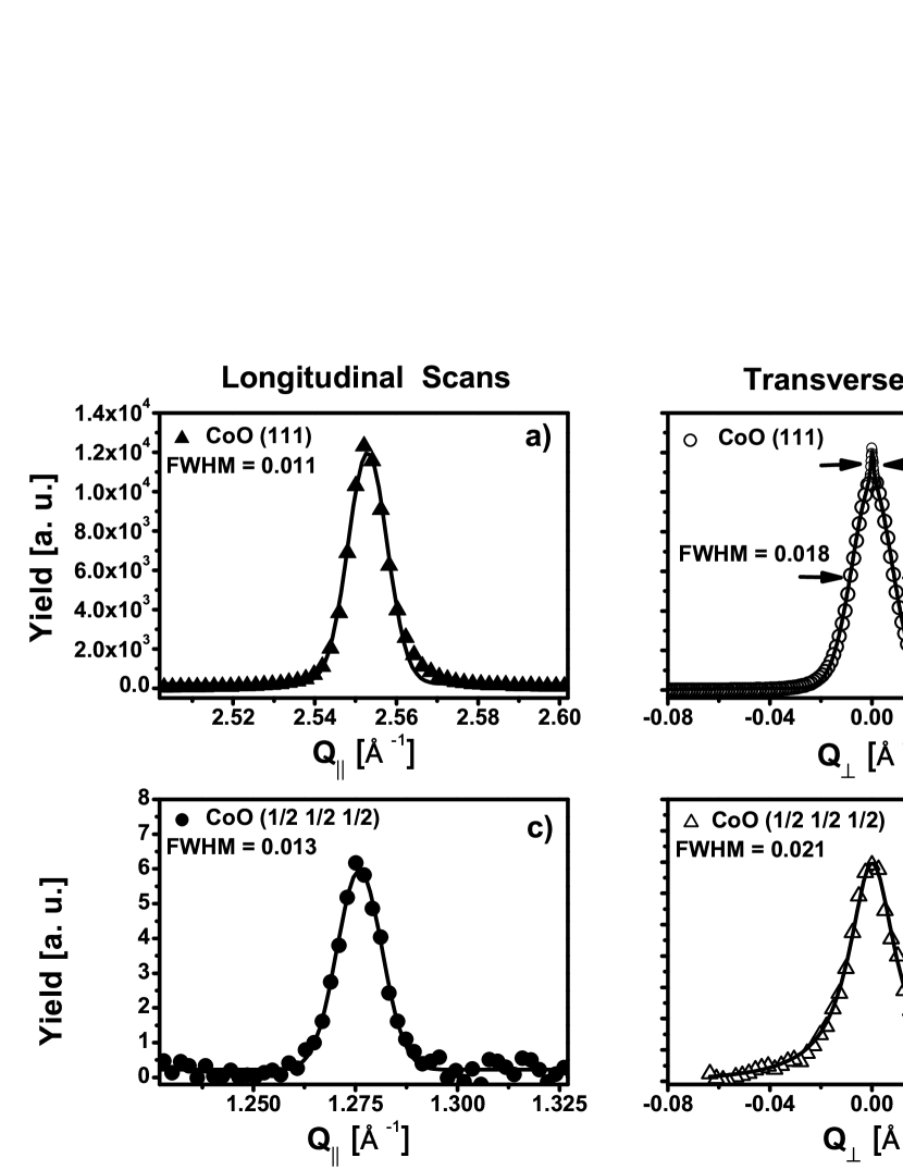
Comparing the structural to the magnetic longitudinal peaks (Fig. 2a versus Fig. 2c) we observe an increase of the full width at half maximum (FWHM) from 0.011 Å-1 to 0.013 Å-1, respectively. The width of the magnetic peak () becomes wider as compared to the structural one (111), suggesting formation of AF domains. Scattering at the magnetic inhomogeneities provided by the domain walls will diminish the average coherence length, providing an increased width of the longitudinal () magnetic peak with respect to its (111) charge scattering counterpart.
The transverse scan shown in Fig. 2d probes the in-plane average size of AF domains, often identified as the magnetic coherence length () Borchers et al. (1995); Béa et al. (2008). An almost Lorentzian shaped transverse scan (Fig. 2d) is indicative for a broad distribution of domain sizes with a mean value of L 30 nm. The widths are free of instrumental resolution. Its shape is also quite different from the structural (111) transverse scan (Fig. 2b). A sharp coherent contribution is clearly visible on top of a much broader diffuse peak. The presence of the sharp peak confirms a high film quality, but random vacancies and stacking faults contribute to the broad diffuse charge scattering which becomes more prominent as the film grows thicker Csizar (2005). Notice that the correlation lengths for both structural and magnetic peaks are very close in magnitude, suggesting that the AF domain size is only slightly smaller as compared to the grain size.
IV Magnetization reversal and the antiferromagnetic domain state by Polarised Neutron Reflectivity and Polarised Neutron Diffraction
Having established the existence of AF domains in the AF layer, we study now their average in-plane orientation using neutrons. Polarised neutron reflectivity(not shown) (sensitive to ferromagnetism) and diffraction (sensitive to the antiferromagnetism) have been performed at the ADAM diffractometer at the Institut Laue Langevin, Grenoble Wolff et al. (2007). Taking advantage of the large scattering angles available (2: 0-125∘), we have accessed the half-order Bragg peak ( ) and measured spin analyzed reflection under the same conditions as low angle neutron reflectivity. The (111) Bragg peak was not accessible due to the large neutron wavelength (=4.41 Å) available for this experiment.
IV.1 Polarised Neutron Reflectivity study of the ferromagnetic layer
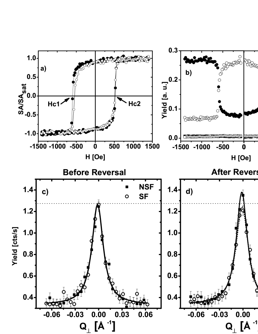
In Fig. 3 the magnetization reversal and the hysteresis loops are shown. The sample has been cooled from above the Néel temperature of CoO (TN=291 K) to 10 K in an external magnetic field of 2 KOe to establish a unidirectional anisotropy. After field cooling in saturation, polarized neutron reflectivity curves were measured at 10 K to find the geometrical conditions (incident and outgoing angles) for maximum magnetic contrast Radu et al. (2003) for the ferromagnetic layer. At this fixed geometry, spin-flip (SF) (I+-,I-+) and non spin-flip (NSF) (I++,I–) reflected intensities were measured by sweeping the magnetic field. The SF intensities sense the magnetization component perpendicular to the applied field and scattering plane, whereas the NSF reflectivities is sensitive to the magnetization components parallel to the applied field. The field where the NSF reflected intensities are equal defines the coercive fields Hc1 and Hc2, whereas the SF provides information on the magnetization reversal. We observe that on both sides of the hysteresis loop the remagnetization process of the ferromagnetic layer proceeds by domain wall movements. This is seen as vanishing SF intensities at the coercive fields. A rotation of the magnetization would lead to a strong increase of the SF reflectivity which is absent at both legs of the hysteresis loop. This contrasts with earlier observations, where an asymmetric reversal has been observed, albeit for a much thinner AF layer Radu et al. (2003); Brems et al. (2005). Defining the spin asymmetry as: , the normalized spin asymmetry () allows us to measure a hysteresis loop. By measuring a second consecutive hysteresis loop, we observe that the system exhibits a small but clear training effect. The characteristics of the hysteresis loops are: a) the magnetization reversal proceeds via domain nucleation and propagation for the first and all consecutive loops; b) the exchange bias field is several orders of magnitude lower than predicted (H 20 Oe) and the coercive field is high H 650 Oe. The exchange bias field is predicted to be H 2000 Oe, whereas the coercive field should not differ from the intrinsic value for the Py layer which is about 5 Oe Meiklejohn and Bean (1956); Radu and Zabel (2008); c) a small training effect is clearly seen by comparing two consecutive hysteresis loops shown in Fig. 3a. Further hysteresis loops exhibits weaker relative changes (not shown).
IV.2 Polarised Neutron Diffraction study of the antiferromagnetic layer
Fig. 3c and Fig. 3d show polarised neutron measurements which are sensitive only to the antiferromagnetic layer, taken after field cooling the sample from above TN to 10 K, before and after reversing the magnetization. Spin analyzed transverse scans were measured at the magnetic ( ) reciprocal point (Fig. 3c). We mention that a 2 contamination of the neutron beam can be excluded due to the vanishing intensity of the half order peak above TN (see Fig. 5a). The transverse scans carry information about the average antiferromagnetic domain size and average orientation. The first observation is that after field cooling the NSF and SF cross-sections are practically equal (see Fig. 3c). This translates into almost equally populated {111} domains with a virtually anisotropic in-plane distribution of the AF spins. On average, an equal number of AF spins are oriented parallel and perpendicular to the ferromagnetic spins, respectively. We have calculated a lateral coherence length of 30 nm, in agrement with the Resonant X-ray Magnetic Scattering results above (compare to Fig. 2d). As a result, the cooling state of the Py/CoO system acquires a noncollinear magnetic state with a virtually anisotropic in-plane distribution of the AF domains, while the FM spins are aligned with the external field.

After reversing the magnetization at Hc1, the magnetic state of the AF layer may change as suggested indirectly by the magnetic interfacial roughness measured before Radu et al. (2002), leading to a training effect. By measuring the magnetic Bragg peak of the AF we access now directly the stability of the AF domain structure upon reversal. The spin-analyzed transverse scans shown in Fig. 3d were measured after a complete hysteresis loop. The external conditions for the scans before and after reversal are identical, therefore, we may directly compare the virgin state of the AF layer after field cooling to the trained one. Surprisingly, after reversal the AF domain state does undergo irreversible changes. Under the influence of a strong direct interfacial coupling some domains appear to rearrange towards their stable configuration. The NSF intensity becomes stronger at the expense of SF scattering. This directly demonstrates that one origin of the training effect can be attributed to AF domain reorientation upon magnetization reversal.
Now we describe an experiment (shown in Fig. 4) which can distinguish between an anisotropic in-plane AF spins orientations and a random AF spin orientational distribution. By an anisotropic in-plane orientations we understand that the AF spins may be directed preferentially parallel to the anisotropy axes provided by the crystallographic axes, whereas a random orientational distribution of the AF spins would exhibit no preferential in-plane orientation. To this end we performed an azimuthal scan by measuring SF and NSF neutron integrated intensities at the ( ) Bragg position while rotating the sample around its normal. Knowing that the scattering is a coherent process and that the SF probability is sensitive to the projection of the spin direction onto the SF axis but not to the absolute orientational angle, one would expect the normalised SF and NSF integrated intensities to be equal to:
| (1) | |||
where the integer is the symmetry number, is the symmetry angle of the anisotropy axes, and is the azimuthal angle with defining the direction of an AF anisotropy axis. To obtain the equations above we also used a conservation law constraining the sum of the NSF and SF intensities to be constant as a function of the azimuthal angle. Assuming the AF spins to be oriented along the crystallographic (anisotropy) directions and making use of the structural data shown in Fig. 1b, we extracted and . For this case, a SF and NSF integrated intensities modulation reflecting the six fold structural symmetry should be observed. For the other case, of randomly in-plane oriented AF spins, the normalised SF and NSF yields should show a straight line as a function of the azimuthal angle. In Fig. 4 the experimental normalized SF and NSF integrated intensities are plotted as a function of the azimuthal angle (). The sample has been cooled down to 10 K in an external field of 2 KOe applied almost parallel to one of the AF anisotropy axis. The field was reversed as to induce the training effect. Then, the external field was reduced to about 50 Oe. We observe clear oscillations with a periodicity of 60 degrees for both NSF and SF signals. The excellent agreement between the expected values (calculated by Eqs. 1 with n=3 and ) based on the crystallographic data and the experimental observations in Fig. 4 leads us to the conclusion that the AF spins follow closely the anisotropy axes. They are not randomly oriented in-plane.
These anisotropic orientations of the AF domains provide on average a virtually compensated interface and, therefore, the exchange bias is several orders of magnitude lower than expected. An AF domain state is at the core of the Domain State model Miltényi et al. (2000); Nowak et al. (2001, 2002a, 2002b); Beckmann et al. (2003); Misra et al. (2004); Scholten et al. (2005); Beckmann et al. (2006). Their orientation is parallel to the anisotropy axis of the AF layer which has an unique direction. Here we observe experimentally a more complex configurations of AF domains, with orientations distributed in-plane and parallel to the three anisotropy axes. The Spin Glass (SG) model Radu and Zabel (2008); Radu et al. (2006a) predicts a reduced AF anisotropy at the interface. This assumption may help to understand this particular domain state. Upon field cooling, the AF acquires its intrinsic domain state inside the film and by further cooling this configuration propagates towards the surface, minimizing the role of interfacial coupling.
To further confirm the influence of the AF domains on the exchange bias we have measured temperature dependent AF Bragg peaks (not shown). They provide information on the antiferromagnetic order in a rather straightforward manner: above the Néel temperature the intensity of the half order peak peak vanishes (see Fig. 5a), whereas at temperatures for which the long range AF order is established it acquires non vanishing values. The integrated peak intensity as a function of temperature provides the order parameter and the Néel temperature, which is 291 K for this sample, in agreement with earlier bulk measurements Roth (1958). Moreover, the width of the AF peak shown in Fig. 5b containes additional information on the temperature dependence of the average AF domain size and the onset of their stability. The FWHM increases linearly as the temperature decreases, which translates into a smaller average domain size at low temperatures. The domain size evolution as function of temperature may be correlated with an increase of the wall width (grain boundary). This may be understood as an interplay between AF anisotropy and stiffness strengths. For instance, assuming random fields, Malozemoff model Malozemoff (1987, 1988a, 1988b) provides an analytical dependence for the characteristic length of the AF domains, namely , where is the exchange stiffness and is the anisotropy of the antiferromagnet. Assuming that the anisotropy grows faster as compared to the exchange stiffness , one would expect a shrinking domain size when decreasing the temperature. The other situation, when grows faster as compared to , would lead to an increased AF domain size. Our experiments show a shrinking average domain size at low temperatures. This allows us to suggest that an anisotropy increase towards lower temperatures predominantly governs the average AF domain size. Another striking behavior is the observation of a characteristic temperature where the AF domains reach stability against the exchange interaction with the FM layer. This blocking temperature is TB=280 K and is lower then the Néel temperature. This correlates remarkably well with the blocking temperature for the exchange bias, to be discussed further below. By contrast, the Néel temperature is the critical temperature which defines the onset of long range spin order (against thermal fluctuations).
V Temperature dependence, frozen-in uncompensated spins, blocking temperature
Soft x-ray magnetic scattering measurements were performed at the UE46 HZB End Station (Fig. 5c) and Alice diffractometer Grabis et al. (2003) (Fig. 5d and Fig. 5e) operated at BESSY. By tuning the energy close to the Co L3 absorption edge, we have measured reflectivity curves which allow us to select the scattering conditions for maximum magnetic contrast Radu et al. (2006b). In this way we measured element specific hysteresis loops as a function of temperature which yield the Hc and HEB shown in Fig. 5d and Fig. 5e, respectively. Flipping the circular helicity of X-rays as well as the magnetic field allows us to separate rotatable and frozen-in AF spins Radu and Zabel (2008) which are depth and laterally uncompensated (Fig. 5c). By contrast an ideal uncompensated monolayer assumed by the Meiklejohn and Bean (M&B) model Meiklejohn and Bean (1957) is essentially depth and laterally compensated (see previous section) for our large AF layer, therefore it will not contribute to a shift of the macroscopic hysteresis loop. Sensitivity to monoatomic uncompensated M&B spins appears to be provided by a more localized probe like x-ray magnetic circular dichroism as debated in Refs. Ohldag et al. (2001); Tsunoda et al. (2006).
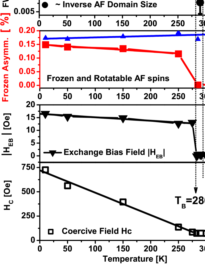
Measuring the reflected intensity for circularly right () and left () polarized x-rays while sweeping the external field, one obtains a hysteresis loop provided by the asymmetry ratio as a function of an external field: . This asymmetry ratio resolves vertical shifts of the hysteresis loops, with respect to the magnetization axis. Now, the frozen-in and rotatable AF uncompensated components are extracted from the positive () and negative () magnetic saturation values of asymmetry as: and , respectively. These two experimental observables are plotted in Fig. 5c as a function of temperature. The sum of rotatable and frozen-in spins is seemingly constant (not shown) and extends through the Néel temperature Radu et al. (2006b); Roy et al. (2007); Abrudan et al. (2008). Note that the rotatable asymmetry component is much larger than the frozen asymmetry. At the blocking temperature, however, 3% of these rotatable AF spins become frozen with a sharp characteristic onset. Note that the absolute asymmetry values for the frozen-in spins (Fig. 5c)) is below 0.0015, which reflects an exceptionally high precision (not achieved before) for these measurements. At lower temperatures a linear increase of the frozen-in asymmetry is clearly observed and correlates with the in-plane AF coherence length. The direct relation between the size of AF domains and the uncompensated spins is intrinsic to the Malozemoff model Malozemoff (1987, 1988a, 1988b). Calculating the HEB for this system within the Malozemoff model Radu and Zabel (2008) one would expect it to be about 600 Oe. The measured HEB value of about 20 Oe is still 30 times lower.
Hc increases linearly as a function of temperature, confirming a strong interfacial coupling. The exchange bias shows, however, a very different behavior. After a sharp onset at the blocking temperature (TB=280 K), it increases linearly towards low temperatures. The blocking temperature can be correlated to the temperature where the AF domains achieve stability against the exchange interaction with the FM layer as observed by neutron scattering (Fig. 5b). This origin of the blocking temperature can be inferred from the M&B model. There, the blocking temperature is always lower than the Néel temperature, and is essentially governed by the magnitude of the AF anisotropy energy and interfacial exchange energy. The temperature where the AF (effective) anisotropy become strong enough to resist the rotation (remagnetization) of the ferromagnetic spins, is defined as blocking temperature Meiklejohn and Bean (1957); Radu and Zabel (2008).
The astounding correlations between the temperature evolution of the AF domain size, frozen-in spins, and value of exchange bias are shown in Fig. 5. The temperature dependence of the HEB and of frozen-in spins is correlated with the average AF domain size and orientation. Characteristic features of three different models can be inferred from these data: the origin of the blocking temperature can be described by the M&B model, the formation of AF domains are intrinsic to the DS and Malozemoff models, and the linear dependence between the AF frozen spins and the AF domain sizes are characteristic to the Malozemoff model, demonstrating their limitations. These features, including the noncollinearity between the AF and FM spins, can all be accounted for by the Spin Glass (SG) model Radu et al. (2006a); Radu and Zabel (2008).
VI Conclusions
In conclusion, we have investigated an archetypal exchange bias bilayer by using complementary neutron and x-ray diffraction techniques. An almost anisotropic orientation of AF domains is observed, thus, clarifying the origin of the reduction of the exchange bias field in epitaxially grown CoO/FM bilayers by several orders of magnitude. The blocking temperature for the exchange bias is the temperature where the antiferromagnetic domains achieve stability against the exchange interaction with the FM layer. By contrast, at the Néel temperature the AF system develops a long range order against thermal fluctuations. At low temperatures, the antiferromagnetic domains are not stable upon magnetization reversal, which is directly identified as one contribution to the training effect. Uncompensated frozen-in spins are found to be remarkably well correlated with the antiferromagnetic domains and the exchange bias field. This strongly supports a mechanism for exchange bias caused by interfacial uncompensated spins.
References
- McEnroe et al. (2007) S. A. McEnroe, B. Carter-Stiglitz, R. J. Harrison, P. Robinson, K. Fabian, and C. McCammon, Nature Nanotechnology 2, 631 (2007).
- Meiklejohn and Bean (1956) W. H. Meiklejohn and C. P. Bean, Phys. Rev. 102, 1413 (1956).
- Baibich et al. (1988) M. N. Baibich, J. M. Broto, A. Fert, F. N. Van Dau, F. Petroff, P. Eitenne, G. Creuzet, A. Friederich, and J. Chazelas, Phys. Rev. Lett. 61, 2472 (1988).
- Binasch et al. (1989) G. Binasch, P. Grünberg, F. Saurenbach, and W. Zinn, Phys. Rev. B. 39, 4828 (1989).
- Berkowitz and Takano (1999) A. E. Berkowitz and K. Takano, J. Magn. Magn. Mater. 200, 552 (1999).
- Nogues and Schuller (1999) J. Nogues and I. K. Schuller, J. Magn. Magn. Mater. 192, 203 (1999).
- Stamps (2000) R. L. Stamps, J. Phys. D:Appl. Phys. 33, R247 (2000).
- Kiwi (2001) M. Kiwi, J. Magn. Magn. Mater. 234, 584 (2001).
- Radu and Zabel (2008) F. Radu and H. Zabel, Springer Tracts in Modern Physics 227, 97 (2008).
- Iglesias et al. (2008) O. Iglesias, A. Labarta, and X. Batlle, Journal of Nanoscience and Nanotechnology 8, 2761 (2008).
- Nikitenko et al. (2000) V. I. Nikitenko, V. S. Gornakov, A. J. Shapiro, R. D. Shull, K. Liu, S. M. Zhou, , and C. L. Chien, Phys. Rev. Lett. 84, 765 (2000).
- Fitzsimmons et al. (2000) M. R. Fitzsimmons, P. Yashar, C. Leighton, I. K. Schuller, J. Nogues, C. F. Majkrzak, and J. A. Dura, Phys. Rev. Lett. 84, 3986 (2000).
- Radu et al. (2002) F. Radu, M. Etzkorn, T. Schmitte, R. Siebrecht, A. Schreyer, K. Westerholt, and H. Zabel, J. Magn. Magn. Mater. 240, 251 (2002).
- Lee et al. (2002) W.-T. Lee, S. G. E. te Velthuis, G. P. Felcher, F. Klose, T. Gredig, and E. D. Dahlberg, Phys. Rev. B. 65, 224417 (2002).
- Gierlings et al. (2002) M. Gierlings, M. Prandolini, H. Fritzsche, M. Gruyters, and D. Riegel, Phys. Rev. B. 74, 092407 (2002).
- Brems et al. (2005) S. Brems, D. Buntinx, K. Temst, C. V. Haesendonck, F. Radu, and H. Zabel, Phys. Rev. Lett. 95, 157202 (2005).
- Paccard et al. (1966) D. Paccard, C. Schlenker, O. Massenet, R. Montmory, and A. Yelon, Phys. Status Solidi 16, 301 (1966).
- Nogues et al. (1996) J. Nogues, D. Lederman, T. J. Moran, and I. K. Schuller, Phys. Rev. Lett. 76, 4624 (1996).
- Hong (1998) T. M. Hong, Phys. Rev. B. 58, 97 (1998).
- Radu et al. (2003) F. Radu, M. Etzkorn, R. Siebrecht, T. Schmitte, K. Westerholt, and H. Zabel, Phys. Rev. B. 67, 134409 (2003).
- Gredig et al. (2002) T. Gredig, I. N. Krivorotov, P. Eames, and D. Dahlberg, Appl. Phys. Lett. 81, 1270 (2002).
- Ali et al. (2007) M. Ali, P. Adie, C. H. Marrows, D. Greig, B. J. Hickey, and R. L. Stamps, Nature Materials 6, 70 (2007).
- Dudzik et al. (2006) E. Dudzik, R. Feyerherm, R. Signorato, and C. Zilkens, J. Synchrotron Rad. 13, 421 (2006).
- Erko et al. (2000) A. Erko, I. Packe, C. Hellwig, M. Fieber-Erdmann, O. Pawlitzki, M. Veldkamp, and W. Gudat, Proceedings of the 11th US National Conference on Synchrotron Radiation Instrumentation, SRI99, AIP Conference Proc. 521, 415 (2000).
- Nowak et al. (2007) G. Nowak, A. Remhof, F. Radu, A. Nefedov, H.-W. Becker, and H. Zabel, Phys. Rev. B. 75, 174405 (pages 8) (2007).
- Gökemeijer et al. (2001) N. J. Gökemeijer, R. L. Penn, D. R. Veblen, and C. L. Chien, Phys. Rev. B. 63, 174422 (2001).
- Nishiyama (1934) Z. Nishiyama, Sci. Rep. Tohoku Univ. 23, 638 (1934).
- Borchers et al. (1995) J. A. Borchers, R. W. Erwin, S. D. Berry, D. M. Lind, J. F. Ankner, E. Lochner, K. A. Shaw, and D. Hilton, Phys. Rev. B. 51, 8276 (1995).
- Béa et al. (2008) H. Béa, M. Bibes, F. Ott, B. Dupe, X.-H. Zhu, S. Petit, S. Fusil, C. Deranlot, K. Bouzehouane, and A. Barthelemy, Phys. Rev. Lett. 100, 017204 (pages 4) (2008).
- Csizar (2005) S. I. Csizar, PhD Thesis, Groningen (2005).
- Wolff et al. (2007) M. Wolff, K. Zhernenkov, and H. Zabel, Thin Solid Films 515, 5712 (2007).
- Miltényi et al. (2000) P. Miltényi, M. Gierlings, J. Keller, B. Beschoten, G. Güntherodt, U. Nowak, and K. D. Usadel, Phys. Rev. Lett. 84, 4224 (2000).
- Nowak et al. (2001) U. Nowak, A. Misra, and K. D. Usadel, J. Appl. Phys. 89, 7269 (2001).
- Nowak et al. (2002a) U. Nowak, A. Misra, and K. D. Usadel, J. Magn. Magn. Mater. 240, 243 (2002a).
- Nowak et al. (2002b) U. Nowak, K. D. Usadel, J. Keller, P. Miltényi, B. Beschoten, and G. Güntherodt, Phys. Rev. B. 66, 014430 (2002b).
- Beckmann et al. (2003) B. Beckmann, U. Nowak, and K. D. Usadel, Phys. Rev. Lett. 91, 187201 (2003).
- Misra et al. (2004) A. Misra, U. Nowak, and K. D. Usadel, J. Appl. Phys. 95, 1357 (2004).
- Scholten et al. (2005) G. Scholten, K. D. Usadel, and U. Nowak, Phys. Rev. B. 71, 064413 (pages 7) (2005).
- Beckmann et al. (2006) B. Beckmann, K. D. Usadel, and U. Nowak, Phys. Rev. B. 74, 054431 (pages 5) (2006).
- Radu et al. (2006a) F. Radu, A. Westphalen, K. Theis-Bröhl, and H. Zabel, J. Phys.: Condens. Matter 18, L29 (2006a).
- Roth (1958) W. L. Roth, Phys. Rev. 110, 1333 (1958).
- Grabis et al. (2003) J. Grabis, A. Nefedov, and H. Zabel, Rev. Sci. Instrum. 74, 4048 (2003).
- Radu et al. (2006b) F. Radu, A. Nefedov, J. Grabis, G. Nowak, A. Bergmann, and H. Zabel, J. Magn. Magn. Mater. 200, 206 (2006b).
- Meiklejohn and Bean (1957) W. H. Meiklejohn and C. P. Bean, Phys. Rev. 105, 904 (1957).
- Ohldag et al. (2001) H. Ohldag, T. J. Regan, J. Stöhr, A. Scholl, F. Nolting, J. Lüning, C. Stamm, S. Anders, and R. L. White, Phys. Rev. Lett. 87, 247201 (2001).
- Tsunoda et al. (2006) M. Tsunoda, T. Nakamura, M. Naka, S. Yoshitaki, C. Mitsumata, and M. Takahashi, Appl. Phys. Lett. 89, 172501 (pages 3) (2006).
- Roy et al. (2007) S. Roy, C. Sanchez-Hanke, S. Park, M. R. Fitzsimmons, Y. J. Tang, J. I. Hong, D. J. Smith, B. J. Taylor, X. Liu, M. B. Maple, et al., Phys. Rev. B. 75, 014442 (pages 6) (2007).
- Abrudan et al. (2008) R. Abrudan, J. Miguel, M. Bernien, C. Tieg, M. Piantek, J. Kirschner, and W. Kuch, Phys. Rev. B. 77, 014411 (2008).
- Malozemoff (1987) A. P. Malozemoff, Phys. Rev. B. 35, 3679 (1987).
- Malozemoff (1988a) A. P. Malozemoff, J. Appl. Phys. 63, 3874 (1988a).
- Malozemoff (1988b) A. P. Malozemoff, Phys. Rev. B. 37, 7673 (1988b).