Interactions with surfaces Drops and bubbles Wetting
Impalement transitions in droplets impacting microstructured superhydrophobic surfaces
Abstract
Liquid droplets impacting a superhydrophobic surface decorated with micro-scale posts often bounce off the surface. However, by decreasing the impact velocity droplets may land on the surface in a fakir state, and by increasing it posts may impale droplets that are then stuck on the surface. We use a two-phase lattice-Boltzmann model to simulate droplet impact on superhydrophobic surfaces, and show that it may result in a fakir state also for reasonable high impact velocities. This happens more easily if the surface is made more hydrophobic or the post height is increased, thereby making the impaled state energetically less favourable.
pacs:
47.55.drpacs:
47.55.D-pacs:
68.08.Bc1 Introduction
Recently, there has been rapidly growing interest in designing artificial surfaces with extreme hydrophobic properties. These efforts have been inspired in particular by biological superhydrophobic surfaces such as plant leaves or insect wings [1, 2]. These surfaces have a hydrophobic coating and they typically have micron-scale roughness which has been found to further enhance the hydrophobicity of the surface. Similar designs have been utilized in order to manufacture artificial, strongly water-repellent surfaces (see, e.g., refs. [3, 4]).
The fact that roughness has a major effect on the hydrophobicity of a surface has long been recognized. As a droplet is deposited on a rough hydrophobic surface, it can be found in two different states. In the first one, known as the impaled or Wenzel state [5], the droplet follows the surface topography and no air is trapped beneath it. The second state is known as the fakir or Cassie-Baxter state [6]. In this state the droplet sits on top of the roughnesses, and some air remains trapped in the hollows and grooves under the droplet. For the fakir droplets, a high contact angle is found. Also the contact angle of a droplet in the Wenzel state is higher than that observed for one on a smooth surface, although not as high as in the fakir state [7]. Usually, a high contact angle is related to a low contact angle hysteresis, which is the most important property of a superhydrophobic surface, even though this relation is not generally true [3, 8, 9]. Therefore, in order to obtain strongly water-repellent behaviour, surface designs leading to fakir droplets are preferred.
The fakir state is often metastable and therefore an impalement transition to the Wenzel state may occur as a result of some external disturbance [10, 11, 12]. As the fakir state is typically the preferred one, it would be important to understand the robustness of this state, and the mechanisms leading to collapse to the Wenzel state, which may dramatically change the hydrophobicity. This issue has recently attracted a lot of interest, and both experimental [11, 13, 14] and numerical [14, 15, 16] techniques have been utilized to elucidate the transition between different superhydrophobic states. These studies have been conducted on microstructured surfaces decorated with regular patterns of posts. The impalement transition can be triggered by several mechanisms, including, among others, external pressure [10], defects on the surface [11], or hydrophilic contaminants deposited on the surface from the air or from the droplet itself [12].
One possibility to study impalement transitions is to consider droplets impacting microstructured hydrophobic surfaces [17, 18]. In this case the dynamic ‘pressure’ due to the impact velocity of the droplet is the mechanism triggering the impalement transition. Recently, Bartolo and co-workers [17] reported of three distinct regimes, in which the qualitative behaviour of an impacting droplet is different depending on the impact velocity. First, if the impact velocity is small enough, droplet lands on the posts and after some oscillations stays on the surface as a fakir droplet. Second, for intermediate impact velocities, droplet bounces off the surface. Third, for high impact velocities, sticky droplets are observed. In this regime, the posts on the surface impale the droplet, and liquid penetrates the volume between the posts. Thus, in the last case, the droplet is found in the Wenzel state.
In this work, we study droplets impacting on a hydrophobic surface patterned by posts with square cross section. We are especially interested in the circumstances under which a droplet is impaled by posts, and when a non-bouncing droplet is observed. Our approach is numerical and utilizes the lattice-Boltzmann method to simulate the behaviour of impacting droplets. In particular, we find the same three regimes as reported by Bartolo et al. in ref. [17]. In addition, under certain circumstances, we find a fourth possible regime for impact velocities larger than those for bouncing droplets but smaller than the ones for sticky droplets. In this state, a non-bouncing droplet that ends up in the fakir state is observed.
2 Lattice-Boltzmann method and the Shan-Chen model
The present simulations were done using the lattice-Boltzmann (LB) method. As this method is well established and throughly covered in a number of review articles and books (see, e.g., refs. [19, 20, 21, 22, 23]), we only briefly discuss here, for the sake of completeness, the basics of the method.
In the LB method, the fluid is described by an ensemble of particles moving along links between lattice nodes of a regular lattice. Time and velocities are discretized such that during one time step particles can move only to neighbouring lattice nodes. The LB fluid properties are determined by single-particle distribution functions which can be interpreted as the probabilities to find a particle at lattice node at time moving with a discrete velocity . These distribution functions evolve according to the LB equation,
| (1) |
Here, the right-hand side of the equation describes the collisions among the particles as a relaxation process towards a local equilibrium which is a low-Mach-number expansion of the Maxwell-Boltzmann distribution. We use the relaxation-time approximation with a single characteristic time scale .
The macroscopic quantities are obtained as velocity moments of the distribution functions. In particular, the mass and momentum densities are given by
| (2) | |||||
| (3) |
respectively.
In order to model a two-phase fluid, we use the multiphase model developed by Shan and Chen [24]. In this model a mean-field interparticle interaction is added to the standard LB equation. This force can be expressed in the form
| (4) |
where is an effective mass ( is a reference density) and is a parameter that adjusts the strength of the interaction. The values of weight factors depend on the magnitude of the corresponding discrete velocity . Here we use the standard D3Q19 model (three-dimensional lattice with 19 discrete velocities), and the weights for this model can be found in ref. [25]. This additional interaction enables simulation of liquid-vapour systems with surface tension. The wetting behaviour of the liquid at solid walls is modelled with a similar type of force added between the solid and the fluid. Here we set a density value to the solid lattice nodes, and the contact angle can be modified through this density.
3 Results and discussion
We use the following geometrical setup in the simulations. The size of the system is lattice nodes, where the last dimension is related to the vertical direction. To the bottom of the system we add an array of posts with a square cross section of size . The distance between neighbouring posts is 10 lattice spacings. The length of the posts is between 10 and 25 lattice spacings.
In the middle of the simulation domain a droplet with a diameter of 105 lattice spacings is initialized. In the beginning of a simulation, we give the droplet an initial (impact) velocity . We choose such values for the simulation parameters that the density ratio of the liquid and vapour phases is approximately 30. Contact angle is slightly varied in the simulations, and the intrinsic contact angle (i.e., the contact angle of a droplet on a perfectly smooth surface) is between and . Notice that all lengths above were given in dimensionless lattice units and the results below are given in terms of appropriate dimensionless numbers.

First we simulated such a case in which the intrinsic contact angle was , and the post height was 20 lattice spacings. We varied the initial velocity and measured the contact time, i.e., the time that the droplet was in contact with the surface before bouncing off. In the non-bouncing cases the contact time obviously approaches infinity. Experimental studies [17, 26] and scaling arguments [26] suggest that contact time does not depend on the impact velocity if this velocity is high enough. However, in their experiments Richard et al. found that, when the Weber number (the ratio of fluid inertia to surface tension) was , contact time increased with decreasing impact velocity [26]. With the parameters used in the present simulations, varied between and . Therefore, the contact times shown in fig. 1 behave as expected. For high impact velocities the contact time stays essentially constant, but for somewhat lower velocities, when is decreased below unity, it increases for decreasing impact velocity.
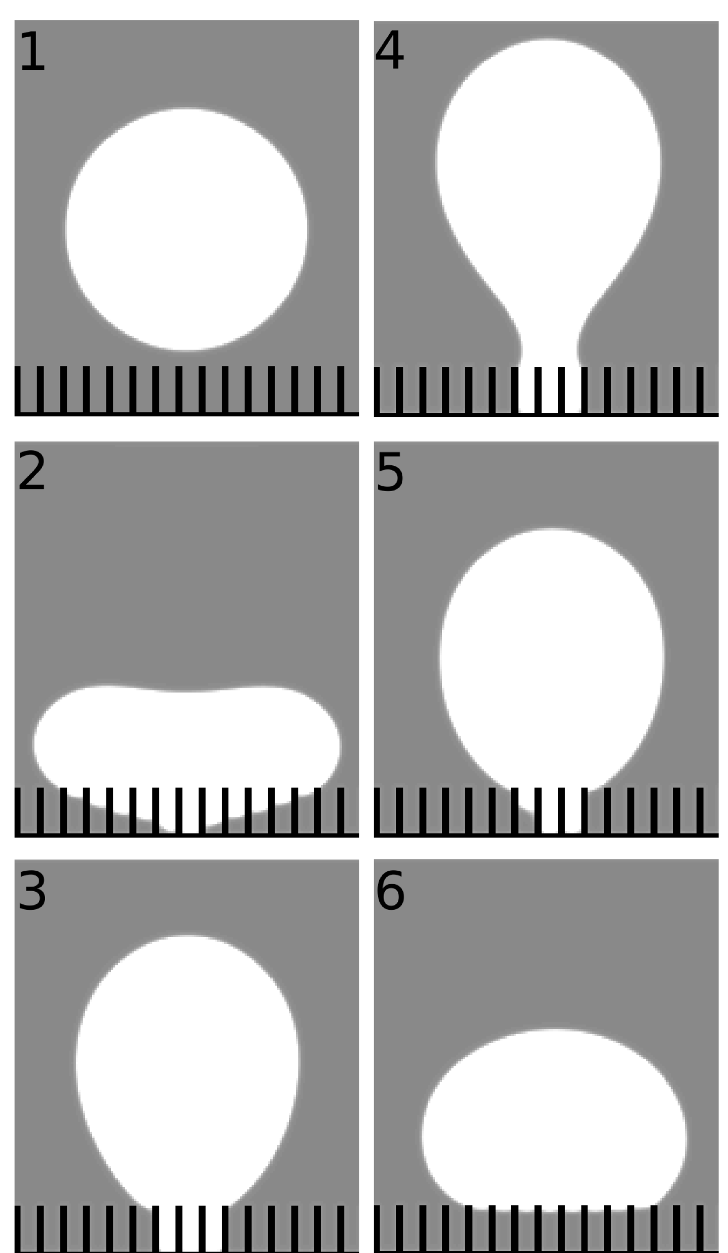
Superficially the contact times shown in fig. 1 lead us to conclude that there are three different regimes in the qualitative behaviour of droplet impact. First, when the impact velocity is low, the contact time is infinite. Second, there is a regime of an almost constant contact time. Third, another regime with infinite contact time is observed at high impact velocities. These regimes would correspond to the non-bouncing, bouncing, and sticky droplets, respectively, as in ref. [17]. However, a closer inspection of the last regime reveals two different types of qualitative behaviour. For very high impact velocities we find the sticky behaviour where the posts impale the droplet. But for lower impact velocities when the contact time still diverges, the droplet is eventually found in the fakir state. In fig. 2 we show a series of snapshots from the impact process in this case. It is evident that posts impale the droplet, but as the droplet bounces, the interpost volume is drained during the process. However, the droplet does not bounce off but remains on the surface and finally ends up in the fakir state. We thus find it in a similar state as in the non-bouncing case although the two processes are different. We distinguish between these two states by calling them the first and second non-bouncing state corresponding to an impact velocity that is lower and respectively higher than that of the bouncing droplet.
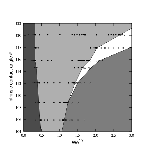
Next we considered how the hydrophobicity of the surface affects the occurrence of the second non-bouncing state. To this end, we simulated droplet impact on surfaces with varying hydrophobicity such that the intrinsic contact angle varied between and . The post heigth was fixed to 15 lattice spacings and also the impact velocity was varied so as to find the velocity intervals where different impact regimes, and especially the second non-bouncing state, are found. The results are shown in fig. 3. We observe that, as the hydrophobicity grows (i.e., the contact angle increases), the second non-bouncing state is found at higher impact velocities, but also the velocity interval of this state becomes wider. Also notice that, for the lowest values of contact angle used in the simulations, we do not observe the second non-bouncing state at all regardless of the impact velocity. It is thus evident that the second non-bouncing state is found easier if the surface is made more hydrophobic.
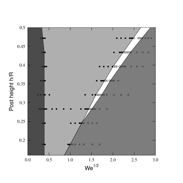
In a similar fashion, we studied the effect of post height. The contact angle was kept contant, , and the simulations were performed on surfaces with post heights between 10 and 25 lattice spacings. The results of these simulations are shown in fig. 4. The qualitative observations from these simulations are similar to those reported above. As the height of the posts is increased, a wider interval of impact velocities leads to the second non-bouncing state. Also, a higher impact velocity is necessary for this state as the post height increases, and when the posts are short enough, the second non-bouncing state is absent.
The results described above are related to the metastability of fakir droplets. As already discussed in the Introduction, the fakir state is typically metastable, but transition to the energetically more favourable impaled state requires external triggering in order to overcome the energy barrier separating these two states. Our investigation shows what happens to an impacting droplet when the impaled state is made less and less favourable. This is exactly what happens when the hydrophobicity of the surface or the length of the posts are increased.
The intrinsic contact angles leading to the second non-bouncing state appears to be quite large. However, such values are still experimentally achievable as the largest contact angle observed on a smooth surface is presumably about as reported by Nishino and co-workers [27]. These authors used trifluoromethyl carbon self-assembled on a surface. Another possibility to achieve high contact angles could be to utilize roughness at different length scales such that the patterned surface itself would be made rough with some smaller-scale roughness. This type of surface design has been proposed by Patankar [28].
4 Summary
In conclusion, we simulated droplets impacting hydrophobic surfaces patterned with regular arrays of posts. Our results were in agreement with those of Bartolo et al. [17], i.e., the behaviour of an impacting droplet depends on the impact velocity such that a non-bouncing, bouncing or sticky droplet results from the impact as the impact velocity increases. We found in addition that, when the impaled state is made energetically less favourable, another non-bouncing state is observed between the bouncing and sticky state. This state might be useful for gaining better understanding of the energy-barrier related mechanisms in droplet impalement and thus for the development of more robust superhydrophobic surfaces.
References
- [1] \NameNeinhuis C. Barthlott W. \REVIEWAnn. Botany791997667.
- [2] \NameLee W., Jin M.-K., Yoo W.-C. Lee J.-K. \REVIEWLangmuir2020047665.
- [3] \NameÖner D. McCarthy T.J. \REVIEWLangmuir1620007777.
- [4] \NameLau K.K.S., Bico J., Teo K.B.K., Chhowalla M., Amaratunga G.A.J., Milne W.I., McKinley G.H. Gleason K.K. \REVIEWNano. Lett.320031701.
- [5] \NameWenzel R.N. \REVIEWInd. Eng. Chem.281936988.
- [6] \NameCassie A.B.D. Baxter S. \REVIEWTrans. Faraday Soc.401944546.
- [7] \NameCallies M. Quéré D. \REVIEWSoft Matter1200555.
- [8] \NameKiuru M. Alakoski E. \REVIEWMater. Lett.5820042213.
- [9] \NameHyväluoma J., Koponen A., Raiskinmäki P. Timonen J. \REVIEWEur. Phys. J. E232007289.
- [10] \NameJournet C., Moulinet S., Ybert C., Purcell S.T. Bocquet L. \REVIEWEurophys. Lett.712005104.
- [11] \NameMoulinet S. Bartolo D. \REVIEWEur. Phys. J. E242007251.
- [12] \NameReyssat M., Yeomans J.M. Quéré D. \REVIEWEurophys. Lett.81200826006.
- [13] \NameHe B., Patankar N.A. Lee J. \REVIEWLangmuir1920034999.
- [14] \NamePirat C., Sbragaglia M., Peters A.M., Borkent B.M., Lammertink R.G.H., Wessling M. Lohse D. \REVIEWEurophys. Lett.81200866002.
- [15] \NameDupuis A. Yeomans J.M. \REVIEWLangmuir2120052624.
- [16] \NameKusumaatmaja H., Blow M.L., Dupuis A. Yeomans J.M. \REVIEWEurophys. Lett.81200836003.
- [17] \NameBartolo D., Bouamrirene F., Verneuil É., Buguin A., Silberzan P. Moulinet S. \REVIEWEurophys. Lett.742006299.
- [18] \NameReyssat M., Pépin A., Marty F., Chen Y. Quéré D. \REVIEWEurophys. Lett.742006306.
- [19] \NameBenzi R., Succi S., Vergassola M. \REVIEWPhys. Rep.2221992145.
- [20] \NameChen S. Doolen G.D. \REVIEWAnnu. Rev. Fluid Mech.301998329.
- [21] \NameWolf-Gladrow D.A. \BookLattice-Gas Cellular Automata and Lattice Boltzmann Models: An Introduction \PublSpringer, Berlin Heidelberg \Year2000.
- [22] \NameSucci S. \BookLattice Boltzmann Equation for Fluid Dynamics and Beyond \PublOxford University Press, Oxford \Year2001.
- [23] \NameSukop M.C. Thorne Jr. D.T. \BookLattice Boltzmann Modeling: An Introduction for Geoscientists and Engineers \PublSpringer, Berlin Heidelberg \Year2006.
- [24] \NameShan X Chen H. \REVIEWPhys. Rev. E4719931815.
- [25] \NameQian Y.H., d’Humieres D. Lallemand P. \REVIEWEurophys. Lett.171992479.
- [26] \NameRichard D., Clanet C. Quéré D. \REVIEWNature4172002811.
- [27] \NameNishino T., Meguro M., Nakamae K., Matsushita M. Ueda Y. \REVIEWLangmuir1519994321.
- [28] \NamePatankar N.A. \REVIEWLangmuir2020048209.