Frustrated total internal reflection and the illusion of superluminal propagation
Abstract
We analyze the propagation of a pulse across a vacuum gap separating opposite flat parallel faces of two transparent dielectrics by means of an explicitly causal and retarded propagator constructed directly from the free-space wave equation. Nevertheless, our approach yields apparently superluminal propagation for the case of frustrated total internal reflection (FTIR), that is, a transmitted wave packet appears on the far side of the gap at the same time that the corresponding incident packet crosses the front one. Thus, in this example superluminality is just an illusion, being consistent with both casuality and classical electrodynamics. We study the origin of the apparent superluminality in this case, which is inherent to light pulse propagation in free space and does not depend on the particulars of light-matter interaction, and find that it is due to propagation from the lateral wings of the incident pulse to the central part of the transmitted pulse. Thus, notwithstanding their similarities, FTIR is not equivalent to 1D tunneling. We propose experiments to test our explanation of superluminality using opaque screens to block part of the wavefront, although we demonstrate that the propagation of smooth finite pulses constrained to be made up completely of evanescent Fourier components is indistinguishable from truly superluminal propagation, i.e., it may be completely accounted for using an explicitely superluminal and acausal propagator as well as the causal subluminal one.
pacs:
42.25.Bs, 41.20.Jb, 03.65.Xp, 42.25.GyI Introduction
The physics of light propagation is a topic of active research, due to its relevance to several technological applications and basic research. Recent research on new materials has shown that it is possible to exercise an extraordinary control on the propagation of light pulses, which in turn has generated new interest in both practical and fundamental questions on light propagation. Moreover, despite the fact that Maxwell completed the formulation of the classical theory of electromagnetism in 1864 and Einstein’s special theory of relativity was presented in 1905, some hot controversies continue to arise on the subject of superluminal propagation Wang et al. (2007); Winful (2007); Pereyra et al. (2007); Ranfagni et al. (2007); Winful (2005, 2003); Buttiker et al. (2003); Windul (2003-1); Buttiker et al. (2003); Winful (2003-2) and its possible implications for both classical and quantum information theory Peres et al. (2004); De Angelis et al (2007). Recent reviews on the subject can be found in Refs. Winful (2006); Boyd et al. (2002)
One consequence of the special theory of relativity is that no signal can cause an effect outside the light cone of its source. Violation of this principle of relativistic causality leads to paradoxes such as that of an effect preceding its cause Azbel’ (1994); Garrison et al (1998). When dealing with light propagation in a material characterized by a given dispersion relation between the frequency and the wave vector , several velocities may be defined, such as the phase velocity and the group velocity . It is recognized that under certain conditions Jackson (Jackson) both velocities can exceed the speed of light in vacuum . This does not contradict the postulates of the special theory of relativity, for it has been recognized since the works of Sommerfeld Sommerfeld (1914) and Brillouin Brillouin1960 (Brillouin) that in order not to violate the principle of causality it is the information velocity that must not exceed . The question that arises then is what is an appropriate and operative definition of information velocity. There have been several discussions and proposals on this subject, but the question is not yet settled Diener (1996, 1997); Kuzmich et al. (2000); Stenner et al. (2003, 2005); Ranfagni et al. (2006).
The vast majority of the published work concerning superluminal pulse propagation deals with light propagation in material media, and the usual analysis attempts to explain how the interaction of electromagnetic radiation with the medium affects the propagation of light pulses in such a way that they appear to travel superluminally. In a pioneering paper Icsevgi et al. (1969), Icsevgi and Lamb performed a theoretical investigation of the propagation of intense laser pulses through a laser amplifier. Apparent superluminal light propagation has been reported in gain-assisted systems wang et al. (2000); Janowicz et al. (2006); Huang et al. (2008) as well as in birefringent crystals solli et al. (2003); Brunner et al. (2004); halvorsen et al. (2008), composite media and photonic crystals Kulkarni et al. (2004); safian et al. (2006) and dispersive media Bigelow et al. (2006); Talukder et al. (2005).
There have also been claims of evidence of superluminal propagation in free space Mugnai et al. (2000, 2005) and during optical tunneling in frustrated total internal reflection (FTIR) configurations Carey et al. (2000); Mochan and Brudny (2001); Carey et al. (2001); Shaarawi et al. (2002). Optical tunneling has been studied by several authors, both theoretically and experimentally Brudny and Mochan (2001); Barbero et al. (2000); Reiten et al. (2001); Balcou et al. (1997); Resch et al. (2001). Some of the observed results are still subject of debatable interpretation Winful (2006) and do not close the subject of whether there are possibilities for superluminal transmission of information in such systems. We have therefore chosen to address this subject in way that leads to straightforward interpretation of the results while resorting only to classical electromagnetic theory. We claim that although some results may appear to indicate superluminal propagation, there is no real superluminal transfer of information.
In this paper we analyze mathematically the propagation of a pulse across a vacuum gap separating opposite flat parallel faces of two transparent dielectrics by means of an explicitly causal and retarded propagator constructed directly from the free-space wave equation. Our results yield indeed an apparent superluminal propagation corresponding to the conditions of FTIR, but they show explicitly that it is consistent with both casuality and with classical electrodynamics. Our example shows superluminality effects inherent to light pulse propagation in free space which therefore does not depend on the particulars of light-matter interaction. The illusion of superluminality consists of transmitted pulses arriving to the far side of the gap in synchrony with the crossing of the front surface by the incident pulse. We explain this illusion of superluminal behavior in terms of a causal, subluminal propagation, taking into account the spatial extent of the incident pulse along its transverse as well as its longitudinal directions and we propose experiments to demonstrate the retarded nature of propagation in FTIR. Nevertheless, we find that for constrained pulses fully made up of evanescent Fourier components, subluminal and superluminal propagation in FTIR experiments are indistinguishable.
This paper is organized as follows. We first introduce a propagator that will allow the analyzis of electromagnetic pulse propagation across a vacuum gap (Section II). This propagator is both casual and retarded and complies with the classical electromagnetic theory. We then study the propagation across the gap of pulses that arrive as plane waves with well defined angles of incidence. In Section III we study the case of subcritical angles, yielding non-evanescent transmitted waves. In Section IV we study the case of hypercritical angles, yielding evanescent waves. We conclude that the propagation of a light pulse in a FTIR configuration may appear superluminal and acausal but that it is actually subluminal and that propagation has to account necessarily for the lateral wings of the incident pulse. In Section V we suggest experiments that might demonstrate the actual causal and subluminal nature of the apparent superluminal behavior by using sharp opaque screens that block parts of the incident wave so that its extent becomes finite along both its propagation and its transverse directions. Nevertheless, as the borders of these screens produce propagating diffracted waves, in Section VI we eliminate them and we study incident pulses that are finite along several spatial directions but that have a smooth profile. We obtain that if they are comprised of evanescent Fourier components only, they appear to propagate superluminally through the vacuum gap, even though their behavior is determined by our causal retarded propagator. In Section VII we construct an alternative acausal, superluminal propagator, and prove that it is exactly equivalent to the causal and retarded propagator when applied to fully evanescent finite pulses. Thus, for such constrained pulses, it is impossible to distinguish causal subluminal from acausal and superluminal propagation; the illusion of superluminality appears to be not only a matter of interpretation of the result of the propagation, but may be also present in the description of the propagation process itself. We present our conclusions in Section VIII.
II Propagator
Consider two transparent dielectrics occupying the regions and . In this section we obtain the causal and retarded propagator that describes the motion of a pulse across a vacuum gap spanning from the interface at to that at (Fig. 1).
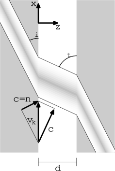
As we want to consider explicitly the angle of incidence onto the interface , we cannot treat the problem beforehand as if it were 1D. For simplicity, we will assume full translational symmetry along the direction, so that our problem becomes 2D. Thus, we start with the scalar wave equation
| (1) |
with a unit singular point source fired at time at position , which is solved by the explicitly causal and retarded free space Green’s function Morse and Feshbach (alguno)
| (2) |
where is the Heaviside unit step function. Using image theory we can construct a Green’s function that obeys Dirichlet boundary conditions at the surface ,
| (3) |
In the half-space Green’s theorem yields the solution Morse and Feshbach (alguno)
| (4) |
of the homogeneous scalar wave equation that is outgoing as and is null in the remote past, where denotes its previous values on the boundary , and
| (5) |
is the causal retarded propagator of the problem. We may identify the field with the component of the electric field in the case of a TE or polarized incoming wave, and with the component of the magnetic field in the case of TM or polarization. The propagator (5) does not account for the presence of the two dielectrics bounding the air gap. Thus, the field (4) has no information about the multiple reflections at the boundary of the gap. In principle, these can be incorporated by reflecting the field at the interfaces using the appropriate Fresnel coefficient and propagating it back and forth across the gap with the propagator (5) for the surface and a similar one for the surface. The total field would then be the sum of all the multiply reflected fields and would have information about the electromagnetic properties of the reflecting surfaces. In this paper we will restrict ourselves to an analysis of the first crossing of the air gap , and thus our results will be unrelated to the nature of the bounding media.
Substituting Eq. (2) into (3) and (5) we obtain
| (6) |
The field can then be written in terms of an ancillary function
| (7) |
where
| (8) |
plays the role of a potential and the integration is performed within the region . Clearly, the procedure above yields a causal (sub)luminal propagation from the plane to any point in the vacuum.
III Non-Evanescent wave transmission
We consider now that an arbitrarily shaped pulse impinges at a well defined angle on the inside surface of a homogeneous non-dispersive dielectric with index of refraction (Fig. 1). The incident pulse is therefore described by an arbitrary function of a single variable , where is a unit vector pointing along the angle of incidence and . Notice that in this case the incident wavefronts have an infinite extension in the direction normal to . At and after being transmitted into vacuum, the outgoing field can therefore be written as
| (9) |
where is related to the arbitrary function and the Fresnel amplitude for transmission from the dielectric into vacuum. As we are concerned only with propagation across the vacuum gap, we will take as given and we will disregard its relation with , which would involve the dielectric properties of the incident medium.
The intersection of the pulse with the interface is therefore seen to travel along with velocity (not to be confused with the parallel component of the incident velocity ). For incidence angles smaller than the critical angle , and we have normal transmission, while for , and total internal reflection ensues.
In order to set up a reference with which to compare the evanescent case, in this section we employ our propagator to study a non-evanescent plane pulse. Thus, we consider here the case and we substitute Eq. (9) into Eq. (8) to obtain
| (10) |
after changing integration variables from to . The integration (10) has to be performed over the region , where . Thus, has an upper bound
| (11) |
where , and for each value of , is bounded by the limits
| (12) |
Consider an event defined by the observation of the field at a given position with and at a given time . Causality requires that only events within the past light-cone of are able to influence it. Notice that a given value of denotes a point that moves along keeping a fixed position with respect to the intersection of the incident pulse with the interface. In Fig. 2 we show the world lines of a few such points. Since each of them moves with speed , most of its world line lies outside the past light cone of . Only if can it actually cross the light cone, entering and leaving at positions and respectively.
After the change of variables from to
| (13) |
Eq. (10) simplifies to
| (14) |
The integration over is immediate, so that substituting Eq. (14 in Eq.(7) we obtain finally
| (15) |
where . Thus, as illustrated in Fig. 1, the transmitted wave is a pulse with the same profile as the incident field and propagating with speed at the well defined angle , in accordance with Snell’s law as could have been expected.
IV Evanescent wave transmission
We consider now the case , for which and the transmitted wave becomes evanescent. In this case we substitute Eq. (9) into Eq. (8) to obtain
| (16) |
after introducing the variables and . As shown in Fig. 3, for any observation event and any value of , there is exactly one intersection between the past light cone of and the world line , where now and we introduced the definitions and . We have assumed that . As the world line leaves the past light cone at , in Eq. (16) the integration over is unconstrained and that over extends from to .
Another change of variable, from to
| (17) |
yields
| (18) |
The integrals over and over in Eqs. (16) and (18) respectively yield an infinite value for . This divergence is not unlike that commonly found for the electromagnetic potentials produced by infinitely extended sources. For example, when calculating the electric field produced by a uniformly charged plane one cannot simply obtain the corresponding potential by integrating the Coulomb kernel over the whole surface. However, in that case the electric field may be obtained either by deriving the Coulomb kernel first and integrating afterwards or else, by truncating the integrations at a finite distance, deriving the resulting potential to obtain the field and afterwards taking the limit of an infinite surface. Here we follow the later procedure. Thus, we set a finite lower integration limit in Eq. (16), corresponding to a lowest point in Eq. (18), and we take the limit , after obtaining the field .
As depends on only through , substituting Eq. (18) in (7) we obtain
| (19) |
In the limit we evaluate
| (20) |
and we obtain finally
| (21) |
Taking the absolute value of in the numerator of Eq. (21) allows its use also for .
To grasp the meaning of Eq. (21) we evaluate it for an infinitely sharp pulse
| (22) |
Substitution into Eq. (21) yields
| (23) |
Surprisingly, at any time the pulse transmitted at a distance from the interface is given by a Lorentzian of width centered in front of the actual position of the incident pulse on the surface (Fig. 4).
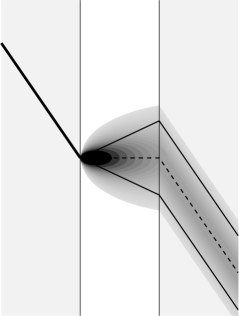
Thus, the propagation seems to be instantaneous in the direction normal to the surface, and actually, part of the pulse seems to travel backwards in time Carey et al. (2000); Resch et al. (2001), as at a position it becomes appreciable at times , that is, before the incoming pulse reaches the corresponding position . However, our deduction of Eq. (22) shows that it is completely consistent with a causal and retarded propagation, and that the field at a at time is not produced instantaneously by the incoming field at , but arises from previously excited positions with .
It is interesting to note that, according to Eq. (23), the height of the transmitted pulse is inversely proportional to the distance from the surface, instead of decaying exponentially as usually found for evanescent waves. However, Eq. (23) describes the propagation into vacuum of a single infinitely sharp incident wavefront. In a wavetrain made up of a succession of incident pulses, the regions excited by neighboring pulses overlap each other, as the width of each transmitted pulse increases in proportion to , and therefore their corresponding fields interfere. This interference is at the origin of the exponential decay of periodic waves, as can be verified by choosing
| (24) |
and substituting into Eq. (21), which yields
| (25) |
A simple contour integration closing the integration path with an infinite semicircle on the lower half complex plane yields the familiar result
| (26) |
where is the parallel component of the wave vector and the inverse of the decay length . As increases, the distance along between successive maxima and minima decreases, yielding larger interference effects and a shorter decay length.
V Screens
The results of the previous section suggest an experiment that could confirm that propagation of evanescent waves in the FTIR geometry is not superluminal nor acausal. The experiment could be performed simply by partially covering the surface of the first interface with a couple of opaque screens as shown in Fig. 5.
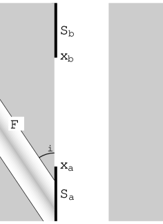
If transmission were indeed superluminal, we would expect a non-null transmitted field across the gap in front of the edge of the first screen as soon as the leading wavefront of the incident pulse reaches . Similarly, we would expect that the field would be modified as soon as reaches the edge of the second screen .
To calculate the field corresponding to Fig. 5 we go back to Eq. (16). The screens confine the integration region to the interval . This inequality has to be obeyed together with the previous constriction . These conditions can only be satisfied by those wavefronts which have reached and left behind the first screen before , where , , is the minimum time required to reach from moving at speed . Thus, only those points on the wavefront labeled by can contribute to (16), where
| (27) |
For those wavefronts which have left by time but have not reached at time , namely, those with , the integral over in Eq. (16) has to be performed from up to . Finally, for those wavefronts which have already been blocked by by time , namely, those with , the upper limit of integration has to be replaced by . Therefore,
| (28) |
where we used the change of variables (17) and substituted in it to define the limits . Notice that depends on only through the integration limits , so that substituting Eq. (28) in (7) we obtain
| (29) |
where
| (30) |
is given by Eq. (20)and with
| (31) |
Substituting Eqs. (17) and (30) in (29) we finally obtain
| (32) |
where
| (33) |
Notice that the field in the presence of screens (Eq. (32)) is given by an expression similar to that corresponding to the field in the absence of screens (Eq. (21)) but with a correction term due to the diffraction by the screen.
As in the previous section, we consider again the case of a sharp incident pulse Eq. (22). Substituting in (32) we obtain
| (34) |
We remark that the field is zero until the time when the incident pulse shows up from behind the screen , and this information has had enough time to propagate from the screen’s edge to the observation point . Similarly, the information that the pulse has hidden behind screen does not reach the observation point until the time . The field has singularities due to the passage of the incident pulse through the screen edges, that propagate at speed from the events and . Notice that as . Thus, if we follow the incident pulse, i.e., we take , then asymptotically after the pulse hides behind . Furthermore, if the screens are very far apart we recover the field (23) between the screens.
The features above are illustrated in Fig. 6
which show the transmitted field at the plane . Notice the delay after the incident pulse crosses at before a non-null field first appears across the gap at , and a similar delay after the incident pulse crosses at before the field starts to be extinguished at . Furthermore, notice that for some time the field penetrates a small distance beyond as if there were no screen. The field is singular at the hyperbolas with vertices at , and at , given by the intersection of the hyperplane and the future light cone of the events , . Thus, we have shown observable consequences of the fact that evanescent waves in FTIR do not propagate superluminally nor acausally in the direction normal to the dielectric-vacuum interfaces, but with retardation and obliquely. A graphical approach to the results of this section and an animation illustrating them may be found in Refs. Mochan and Brudny, 2001 and Ref. Brudny and Mochan, 2001 respectively.
VI A smooth transverse profile
Perfectly opaque screens such as those considered in the previous section introduce sharp discontinuities in the pulse at . The truncated pulse no longer has a well defined propagation direction but may still be represented by a superposition of pulses with varying propagation directions. A sharp truncation leads to the presence of subcritical incident angles , and therefore to the presence of both, evanescent and non-evanescent transmitted fields. It has been argued Carey et al. (2001) that the retardation effects discussed in the previous section may be due only to the non-evanescent contributions, known to be subluminal. The comparatively slow subluminal contributions would be unable to affect the arrival of the superluminal signals if the later were actually present. However, any small non-evanescent wave would dominate the transmitted signal after a wide enough gap. Thus, it is interesting to study the propagation of pulses with a finite transverse extension but with a smooth lateral cutoff and built up completely from hypercritical evanescent contributions.
To explore the propagation of the smoothly truncated pulses discussed above, we consider an incoming field given by a Fourier integral
| (35) |
where is the amplitude for each parallel component of the wave vector and frequency . We can change integration variable from to the parallel velocity ,
| (36) |
where we introduced the velocity dependent amplitude . The incident field (36) will give rise to evanescent waves exclusively as long as all non-null components have . At this point we could integrate first Eq. (36) with respect to , obtaining thus a superposition of plane pulses, each of which may be propagated across the air gap according to Eq. (21). Alternatively, we may propagate each monochromatic component using Eq. (26) and afterward perform the integrations in Eq. (36). We follow the later approach and write
| (37) |
where as in Sec. IV. For simplicity we assume that we may factor into frequency and velocity dependent amplitudes, and respectively; controls the time duration of the pulse, or equivalently, its longitudinal extent, while controls its transverse extent. We further assume a narrow Gaussian velocity distribution of width around a nominal velocity ,
| (38) |
where . We assume is small enough that the non-evanescent contributions to the field may be neglected and the exponent in Eq. (37) may be linearized in . Thus, the transmitted field becomes
| (39) |
where . The integration over is immediate and yields
| (40) |
In Fig. 7 we illustrate the results of applying Eq. (40) to a pulse with a Gaussian frequency distribution,
| (41) |
of area and width centered at (, , , ).

The pulse is seen to form on the surface at and at time , it propagates along the line for a while, peaks at at time and disappears at , . Its maximum duration and size are for a fixed position and fixed observation time respectively, and it contains altogether about six nodes.
Surprisingly, after crossing the gap, the pulse looks essentially the same! It appears at the back face of the air gap at roughly the same time and the same position as at the front face. It also peaks at the origin at and disappears from the back surface in concordance to the incident pulse on the front face. Thus, it truly appears to propagate instantaneously. The main difference between the incident and transmitted pulse is that the intensity of the later is suppressed by 12 orders of magnitude. Another interesting difference is that the number of visible nodes in the transmitted pulse has decreased to about 4. This is a consequence of the fact that in FTIR, the Fourier components with higher frequencies are more damped than those with lower frequencies. Finally, a more subtle difference is that the speed of propagation along the back face is slightly but noticeably larger than that on the front face. This is due to the fact that plane waves incident at angles closer to have a larger penetration length than waves incident at larger angles. Thus, the angle of propagation of the transmitted pulse is smaller than that of the incident wave Balcou et al. (1997).
In Sec. IV we have argued that the transmission of evanescent plane pulses across an air gap under FTIR conditions is fully consistent with a retarded and causal propagation along oblique directions. We have strengthened our argument by showing that there is a delay before a perturbation, such as blocking part of the incident wavefront, can produce an effect on the pulse transmitted across the gap. Furthermore, by truncating an incident plane pulse producing an abrupt transverse profile, we showed that the transmitted pulse is shifted along the surface in the direction of propagation. However, in Sec. VI we showed through an example that if the pulse has a smooth transverse profile, such that all its Fourier components are evanescent, it is transmitted as if it were indeed superluminal. To understand this result, in Fig. 8 we show schematically a pulse smoothly truncated along its transverse direction, built from narrow plane components propagating along well defined directions .
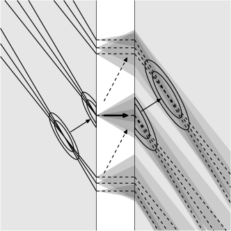
The incident field peaks at the regions where the directional components add in phase, indicated in the figure by elliptical regions around the crossing point of the different incident wavefronts. As each of the components crosses the gap, it is widened according to Eq. (23). The peak of the transmitted pulse appears in the regions of largest overlap between the different widened transmitted components, i.e., at the regions where their centers coincide. The peak of the transmitted pulse at the back face of the air gap is seen to appear at the same time as the peak of the incident pulse reaches the front surface. Thus, it would seem as if the peak tunneled instantaneously in the direction normal to the gap. However, in the previous sections we have shown that each of the transmitted components of the transmitted wave originates causally from regions in the lateral wings of the incident pulse. Thus, the peak of the transmitted field does not actually originate from the peak of the incident field; it is formed by contributions from the lateral wings of the incident field, which reach the front face of the air gap first. The lateral wings of each component have enough time to cross the gap traveling at speed and combine to form the relatively small transmitted peak right at the time when the larger incident peak reaches the front surface. Similarly, the different components of the field produced by the peak of the incident pulse get out of step as they cross the air gap and, therefore, do not contribute to the peak of the transmitted pulse, but rather, to its lateral wing. This is illustrated by the dashed arrows in Fig. 8. Thus, it seems that the physical propagation (retarded and causal) can not be distinguished from the nonphysical propagation (superluminal and non-causal) as long as we only consider smooth incident pulses which contain only propagation directions above the critical angle Carey et al. (2000, 2001).
VII Evanescent propagator
In Sec. VI we found that a particular pulse made up of only evanescent components seemed to propagate instantaneously across the air gap, in contrast to the abruptly truncated pulses considered in Sec. V for which retardation effects have observable consequences. This was explained graphically in Fig. 8 for incident pulses built up from narrow directional components, each of which is widened as it is transmitted across the gap. To show that this behavior is generic, we start from the Fourier decomposition of an arbitrary field
| (42) |
where
| (43) |
The condition that is made up exclusively of evanescent waves is equivalent to stating that the integration region in Eq. (35) is given by , i.e., if . Using Eq. (26) we propagate each Fourier component from to as
| (44) |
where . Thus, we can combine Eqs. (42), (43) and (44) to obtain
| (45) |
where
| (46) |
and the integration region is given by . Comparing Eq. (45) with (4) we find that is a propagator that can be used in the same way as the propagator defined in Eq. (6) to find the value of the field at given its values at , provided the field is built up of evanescent components only, as in the examples of the two previous sections. We remark that our original causal, retarded and subluminal propagator was able to propagate any arbitrary outgoing field. However, by adding constrains to the field, we gain freedom in our choice of propagator, as we can chose arbitrarily its effect on fields that do not obey the constrain. Thus, if we can find any function such that
| (47) |
for an arbitrary flat pulse moving along with any velocity , then we could employ instead of to propagate an arbitrary evanescent pulse. above is just one of the many possible choices of a propagator for evanescent pulses.
To proceed, we make a change of variable to write Eq. (46) as
| (48) |
where , , and we perform the integration over ,
| (49) |
Notice that is symmetric under the interchange and also under the interchange , i.e., . Thus, the evanescent propagator is superluminal and acausal.
To finish the calculation of we make another change of integration variable to write
| (50) |
and we perform the integration
| (51) |
where is the spatial distance from the source to the observation point and is the squared space-time interval. This expression may be simplified to
| (52) |
The evanescent propagator is displayed in Fig. 9.

The figure shows explicitly the temporal and spatial symmetry, and thus the superluminality and non-causality of . Notice that has singularities at the projected light-lines which converge at the origin , . Thus, propagation is largest for instantaneous propagation in the direction normal to the air gap.
We have found that the propagation of evanescent pulses can be described with either the exact propagator of the problem, which is causal, retarded and subluminal, or with an evanescent propagator which is superluminal and non-causal. Both yield exactly the same transmitted pulse when the incident pulse contains only evanescent components. Thus, it seems to be impossible to distinguish superluminal from subluminal propagation in experiments performed with purely evanescent pulses Carey et al. (2001).
An explanation for the curious conclusion found in this section can be obtained by going back to Eq. (42) which we rewrite as
| (53) |
Notice that for each finite wave vector , the time dependent Fourier component has a strictly finite spectrum . Thus, is an analytical function of with no singularities and can be analytically continued to an arbitrary time from its values in an arbitrarily small neighborhood of any other arbitrary time . Therefore, is perfectly predictable in principle. Using antropomorphic language, we may say that at time the system knows from the present values of what its future values will be, and thus it can use that knowledge to build subluminally a transmitted pulse that will mimic , giving the impression that superluminal transmission has taken place at time . The validity of the argument above in the presence of thermal or quantum noise has to be investigated.
VIII Conclusions
To study the propagation of a light pulse through a vacuum gap between two parallel dielectrics in a FTIR configuration we constructed a propagator derived directly from the wave equation resulting from Maxwell’s equations. This propagator is retarded and complies with the relativistic causality principle inherent to classical electromagnetism. Therefore, it can only account for causal, (sub)luminal propagation of light pulses. However, when this propagator is used to study the propagation of wave packets through the gap, we find apparent superluminal behavior, that is, a wave packet might appear on the far side of the gap at the same time that the incident packet reaches the front one. Therefore this illusion of superluminality, present within classical electromagnetic theory even in vacuum, is fully consistent with relativistic causality. We showed explicitly that propagation in FTIR actually takes place subluminally between the lateral wings of the incident pulse and the central peak of the transmitted pulse, and we proposed simple experiments that could verify this statement. Thus, although FTIR has many similitudes to 1D tunneling, its correct physical interpretation requires a 2D or 3D analysis. On the other hand, we constructed an explicitly superluminal and acausal propagator that yields identical results as the retarded causal one when applied to smooth pulses made up of evanescent contributions only. Thus, there is a class of pulses for which superluminal and subluminal propagation would be indistinguishable.
Acknowledgements.
We acknowledge partial support from UBACYT and CONICET (VLB) and from DGAPA-UNAM under project IN111306 (WLM). VLB is a member of CONICET.References
- Wang et al. (2007) Zhi-Yong Wang and Cai-Dong Xiong, Phys. Rev. A 75, 042105 (2007).
- Winful (2007) H. G. Winful, Phys. Rev. A 76, 057803 (2007).
- Pereyra et al. (2007) P. Pereyra and H.P. Simanjuntak, Phys. Rev. E 75, 056604 (2007).
- Ranfagni et al. (2007) A. Ranfagni, G. Viliani, C. Ranfagni, R. Mignani, R. Ruggeri and A.M. Ricci, Phys. Lett. A 370, 370 (2007).
- Winful (2005) H. G. Winful, Phys. Rev. E 72, 046608 (2005).
- Winful (2003) H. G. Winful, Phys. Rev. Lett 90(2), 23901 (2003).
- Buttiker et al. (2003) M. Buttiker and S. Washburn, Nature 422, 271 (2003).
- Windul (2003-1) Herbert G. Winful, Nature 424, 628 (2003).
- Buttiker et al. (2003) M. Buttiker and S. Washburn, Nature 424, 638 (2003).
- Winful (2003-2) H. G. Winful, Phys. Rev. E 68, 016615 (2003).
- Peres et al. (2004) A. Peres and D. Terno, Rev. Mod. Phys. 76, 93 (2004).
- De Angelis et al (2007) T. De Angelis, E. Nagali, F. Sciarrino and F. De Martini, Phys. Rev. Lett. 99, 193601 (2007).
- Winful (2006) H. G. Winful, Physics Reports 436, 1 (2006).
- Boyd et al. (2002) R. W. Boyd and D.J. Gauthier, Progress in Optics, Vol. 43, E. Wolf (ed.) (Elsevier, Amsterdam, 2002).
- Garrison et al (1998) J. C. Garrison, M. W. Mitchell, R. Y. Chiao and E. L. Bolda, Phys. Lett. A 245, 19 (1998).
- Azbel’ (1994) Mark Ya. Azbel’, Solid State Commun. 91(6), 439 (1994).
- Jackson (Jackson) J. D. Jackson, Classical Electrodynamics (Wiley, New York, 1975), 2nd. ed.
- Sommerfeld (1914) A. Sommerfeld, Ann. Physik 44, 177 (1914). English translation available in Chap. II of Brillouin1960 (Brillouin).
- Brillouin1960 (Brillouin) L. Brillouin, Wave Propagtion and Group Velocity (Academic Press, New York, 1960).
- Diener (1996) G. Diener, Phys. Lett. A 223, 327 (1996).
- Diener (1997) G. Diener, Phys. Lett. A 235, 118 (1997).
- Kuzmich et al. (2000) A. Kuzmich, A. Dogariu, L.J. Wang, P.W. Milonni and R.Y. Chiao, Phys. Rev. Lett. 86, 3925 (2001).
- Stenner et al. (2003) M.D. Stenner, D.J. Gauthier and M.A. Neifeld, Nature 425, 695 (2003).
- Stenner et al. (2005) M.D. Stenner, D.J. Gauthier and M.A. Neifeld, Phys. Rev. Lett. 94, 053902 (2005).
- Ranfagni et al. (2006) A. Ranfagni, P. Fabeni, G.P. Pazzi, A.M. Ricci, R. Trinci, R. Mignani, R. Ruggeri and F. Cardone, Phys. Lett. A 352, 473 (2006).
- Icsevgi et al. (1969) A. Icsevgi and W.E. Lamb, Phys. Rev. 185(2), 517 (1969).
- wang et al. (2000) L.J. Wang, A. Kuzmich and A. Dogariu, Nature (London) 406, 277 (2000).
- Janowicz et al. (2006) M. Janowicz and J. Mostowski, Phys. Rev. E 73, 046613 (2006).
- Huang et al. (2008) G. Huang, Ch. Hang and L. Deng, Phys. Rev. A 77, 011803(R) (2008).
- solli et al. (2003) D.R. Solli, C.F. McCormick, C. Ropers, J.J. Morehead, R.Y. Chiao and J.M. Hickmann, Phys. Rev. Lett. 91, 143906 (2003).
- Brunner et al. (2004) N. Brunner, V. Scarani, M. Wegmüller, M. Legré and N. Gisin, Phys. Rev. Lett. 93, 203902 (2004).
- halvorsen et al. (2008) T.G. Halvorsen and J.M. Leinaas, Phys. Rev. A 77, 023808 (2008).
- Kulkarni et al. (2004) M. Kulkarni, N. Seshadri, V.S.C. Manga Rao and S. Dutta Gupta, J. Mod. Opt. 51, 549 (2004).
- safian et al. (2006) R. Safian, C.D. Sarris and M. Mojahedi, Phys. Rev. E 73, 066602 (2006).
- Bigelow et al. (2006) M.S. Bigelow, N.N. Lepeshkin, H. Shin and R.W. Boyd, J. Phys.: Condens. Matter 18, 3117 (2006).
- Talukder et al. (2005) A.I. Talukder, T. Haruta and M. Tomita, Phys. Rev. Lett. 94, 223901 (2005).
- Mugnai et al. (2000) D. Mugnai, A. Ranfagni and R. Ruggeri, Phys. Rev. Lett. 84, 4830 (2000).
- Mugnai et al. (2005) D. Mugnai and I. Mochi, Phys. Rev. E 73, 016606 (2006).
- Carey et al. (2000) J. J. Carey, J. Zawadzka, D. A. Jaroszynski and K. Wynne, Phys. Rev. Lett. 84, 1431 (2000).
- Mochan and Brudny (2001) W.L. Mochán and V.L. Brudny, Phys.Rev.Lett 87, 119101 (2001).
- Carey et al. (2001) J. J. Carey, J. Zawadzka, D. A. Jaroszynski and K. Wynne, Phys. Rev. Lett. 87, 119102 (2001).
- Shaarawi et al. (2002) A. M. Shaarawi, B. H. Tawfik and I. M. Besieris, Phys. Rev. E. 66, 046626 (2002).
- Brudny and Mochan (2001) V.L. Brudny and W.L. Mochán, Optics Express 19(11) 561(2001).
- Barbero et al. (2000) A. P. Barbero H. E. Hernández-Figueroa and E. Recami, Phys. Rev. E 62(6), 8628 (2000).
- Reiten et al. (2001) M. T. Reiten D. Grischkowsky and R. A. Cheville, Phys. Rev. E 64, 036604 (2001).
- Balcou et al. (1997) Ph. Balcou and L. Dutriaux, Phys. Rev. Lett. 78(5), 851 (1997).
- Resch et al. (2001) K.J. Resch, J.S. Lundeen and A.M. Steinberg, IEEE J. Quantum Electron. 37(6), 794 (2001).
- Morse and Feshbach (alguno) Phillip M. Morse and Herman Feshbach, Methods of Theoretical Physics (Mc.Graw-Hill, New York, 1953).