Further author information: (Send correspondence
to F.F.)
F.F: E-mail: frontera@fe.infn.it, Telephone: +39 0532 974 254
Focusing of gamma-rays with Laue lenses: first results
Abstract
We report on the first results obtained from our development project of focusing gamma-rays (60 keV) by using Laue lenses. The first lens prototype model has been assembled and tested. We describe the technique adopted and the lens focusing capabilities at about 100 keV.
keywords:
Laue lenses, gamma-ray instrumentation, focusing telescopes, gamma-ray observations1 INTRODUCTION
Experimental hard X–/gamma–ray astronomy is moving from direct sky-viewing telescopes to focusing telescopes. With the advent of focusing telescopes in this energy range, a big leap in sensitivity is expected, by a factor of 100-1000 with respect to the best non-focusing instruments of the current generation, either using coded masks (e.g., INTEGRAL/IBIS, Ref. 1) or not (e.g., BeppoSAX/PDS, Ref. 2). A significant increase in angular resolution is also expected (from arcmin of the mask telescopes like INTEGRAL IBIS to less than 1 arcmin).
The next generation of hard X–(100keV) and gamma–ray ( 100 keV) focusing telescopes will make use of the Bragg diffraction technique, in the former energy range, from multilayer coatings (ML) in a reflection configuration (supermirrors), while in the latter, from mosaic–like crystals in a transmission configuration (Laue lenses).
The expected astrophysical issues that are expected to be solved with the advent of these telescopes are many and of fundamental importance. For what concerns the higher energy band (100 keV), a summary of the main science goals are discussed in the context of a mission proposal, Gamma Ray Imager (GRI), submitted to ESA in response to the first AO of the ’Cosmic Vision 2015–2025’ plan [3]. For the astrophysical importance of the 100 keV band, see also Refs. 4, 5, 6, 3. The GRI proposal was not admitted by ESA for further consideration for a launch in 2017 (the first flight opportunity in the new ESA plan) mainly due to readiness problems of the Laue lenses.
Here we report on the status of our project HAXTEL (= HArd X-ray TELescope) devoted to developing the technology for building broad energy passband (70/100–600 keV) Laue lenses, highlighting test results of the first lens prototype.
2 Summary of the lens design study results
The results of the Laue lens development activity over the last few years have been reported and discussed (see Refs. 5, 7 and references therein).
In short, by means of theoretical calculations and the development of a Monte Carlo code, we first established the best geometrical configuration of a Laue lens for space astronomy, the best crystal materials, and the crystal mosaic properties that give the best compromise between reflection efficiency and focusing capabilities. This theoretical study was followed by reflectivity measurements of mosaic crystal samples of Cu(111) [8], given that this material showed good expected performance for our goals and could be developed with the desired properties (e.g., Courtois et al.[9]).
Given that a Laue lens focusing telescope for gamma–ray astronomy is required to have a spherical–like shape in addition to a large size (meter scale), while the available mosaic crystal sizes are generally small (cm scale), the only viable solution is to build a lens made of many crystal tiles. This means that, in order to correctly focus the photons reflected from all crystal tiles toward the same point, the direction of the vector perpendicular to the mean lattice plane of each crystal tile has to intersect the lens axis, while its inclination with respect to the focal plane has to be equal to the Bragg angle (see Fig. 1 in Ref. 8). The angle also establishes the energy centroid of the reflected photons, and it depends on the distance of the tile center from the lens axis and on the focal length . For correct focusing, . Once the crystal material is established, the Bragg angle increases with , while the energy of the focused photons decreases with . More generally, once the focal length is established, the outer and inner lens radii, and , depend on the nominal energy passband of the lens (, ) and on the crystal lattice spacing: higher implies lower radii [5]. For a given crystal material, outer lens radius and focal length, the minimum energy that can be focused is established.
For a given inner and outer radius, the lens passband can be established by the combination of the different crystal materials used. In addition to Copper, other candidate materials, which exhibit high reflectivity and for which the mosaic technology has been developed, are becoming available for Laue lenses, such as mosaic Ge, Si1-xGex, with a composition–gradient [10], or mosaic Gold [11].
Mosaic spread and crystal thickness are the most crucial parameters for the optimization of the lens performance. The crystal thickness issue was investigated by us in relation to the lens weight (e.g., Ref. 12). Concerning the mosaic spread, a higher spread gives a larger effective area, but also produces a larger defocusing of the reflected photons in the focal plane. We introduced a parameter that characterizes a Laue lens and its sensitivity: the focusing factor
| (1) |
in which is the effective area of the lens and is the area of the focal spot which contains a fraction of photons reflected by the lens. The higher is, the higher is the lens sensitivity (minimum detectable source flux ).
The spatial distribution of the mosaic crystal tiles influences the shape of the effective area vs. energy. For low focal lengths ( m), the best crystal tile disposition is an Archimedes’ spiral [13], that provides a smooth behavior of the lens effective area with energy. For high focal lengths, a ring crystal disposition is equally good.
The accuracy of the crystal tile positioning in the lens depends not only on the mosaic spread but also on the focal length. Higher focal lengths require a higher positioning accuracy. At the current stage of development, an accurate positioning of the crystals in the lens is one of the major problems to be faced.
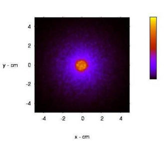
From Monte Carlo (MC) studies, we have derived the properties of various lens configurations, such as their Point Spread Functions (PSF), for both on–axis and off–axis incident photons. We show in Fig. 1 the expected PSF of a Cu (111) gamma–ray Laue lens with a focal length of 40 m and a mosaic spread of 1 arcmin, in which a perfect positioning of the composing crystals is assumed. The expected angular resolution of this lens is of the order of or even better than 1 arcmin.
3 Prototype Model Development
The first Laue lens Prototype Model (PM) has been developed. Unlike the Laue lens described in Ref. 14, the PM developed is made of crystal tiles rigidly fixed to the lens frame, without any mechanism for adjustment of their orientation in the lens, thus their correct positioning in the lens is performed during the lens assembly. The goal of the first PM is to test the lens assembling technique adopted.
3.1 Lens assembly technique
Details of the lens assembling steps have already been reported [7]. The adopted lens assembling technique is based on the use of a counter-mask provided with holes, two for each crystal tile. Each tile is placed on the countermask by means of two pins, rigidly glued to the tile, that are inserted in the countermask holes. The pin direction and the axis of the average lattice plane of each crystal tile have to be exactly orthogonal. The hole direction constrains the energy of the photons diffracted by the tile, while the relative position of the each two holes in the countermask establishes the azimuthal orientation of the mean crystal lattice plane, that has to be othogonal to the lens axis. Depending on the countermask shape and, mainly on the direction of the hole axes, the desired geometry of lens can be obtained. In the case of a lens for space astronomy, the hole axes have to be all directed toward the center of curvature of the lens.
In the case of the developed PM, the hole axes are set parallel to the of the lens axis. This choice has been made to illuminate the entire lens with the available test gamma–ray beam, which is isotropic, being generated by an X–ray tube, and also highly divergent, as the source is only a small distance away ( m) from the lens.
Once the average direction of the chosen lattice planes (111) of each Cu mosaic crystal tile has been determined, the two pins, inserted in a pin holder, are glued to the lens. The pin holder direction is preliminarly made parallel to the gamma–ray beam axis and thus to the direction of the average crystalline plane chosen (in our case, the (111) planes).
Once all the crystal tiles are placed on the counter-mask, a frame is glued to the entire set of the crystals. Then the lens frame, along with the crystals, is separated from the counter-mask and from the pins by means of a chemical etching that dissolves the aluminum caps that cover the pin bases glued to each crystal.
The average direction of the chosen crystalline planes and of the pin axes are determined by means of an X–ray beam developed for this project and located in the LARIX (LArge Italian X–ray facility) lab of the University of Ferrara For a LARIX description see Ref. 15). A view of the experimental apparatus used to assemble and test the lens PM is shown in Fig. 2.
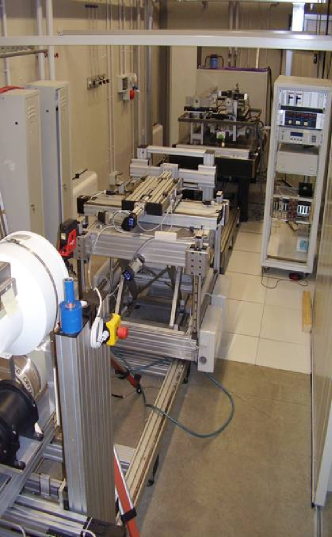
As discussed in Ref. 7, the developed apparatus includes an X–ray generator tube with a fine focus of 0.4 mm radius, a maximum voltage of 150 kV and a maximum power of W.
The photons coming out from the gamma–ray source box are first collimated, with the beam axis made horizontal and directed toward the centre of a large (30 cm diameter) X–ray imaging detector whose position sensitivity is 300 m. The collimator aperture can be remotely adjusted in two orthogonal directions in order to have the desired X–ray beam size [7]. In addition to the X–ray imaging detector, a cooled HPGe detector and a position sensitive (2 mm) scintillator detector are available.
For each mosaic crystal tile, the direction of the average lattice plane was determined with an accuracy better than 10 arcsec [7], while the alignment of the pin axis with the beam direction was performed with an estimated accuracy of 1 arcminute.
4 Developed PM
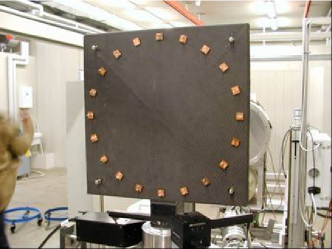
The mounted PM is shown in Fig. 3. The PM is composed of a ring of 20 mosaic crystal tiles of Cu(111). The ring diameter is 36 cm. The mosaic spread of the used crystals ranges from and arcmin. The tile cross–section is 1515 mm2 while its thickness is 2 mm. The lens frame is made of carbon fiber of 1 mm thickness.
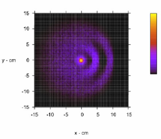
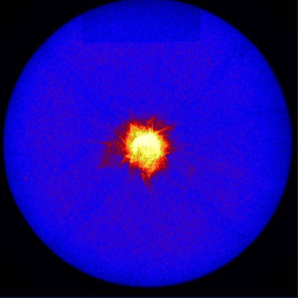
The PM was widely tested using the polychromatic X–ray beam described above. To this end the lens was positioned on the same holder used to determine the direction of the crystalline planes of each crystal tile. The detectors, mounted on a frame whose distance from the lens can be adjusted, were positioned at the same distance of the X–ray source from the lens ( m), where the focal plane is expected. In order to avoid that direct radiation could arrive onto the focal plane detectors, a lead shield 3 mm thick covered the entire inner lens frame. The background radiation was measured when the X–ray tube was switched on, with the X–ray beam stopped before arriving to the lens plane. Figure 4 shows the first light of the lens when the X–ray polychromatic beam irradiates all the lens crystals.
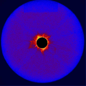
In order to compare the measured PSF with that expected, we have developed a Monte Carlo code that simulates the same lens, in which the mosaic crystal tiles are perfectly positioned. The PSF of this lens has been derived for the same diverging X–ray beam. The difference between the measured PSF of Fig. 4 and the simulated one is shown in Fig. 5. As can be seen, only the center part of the measured image (the black region) is subtracted by the simulated image. The corona still visible in the difference image is the result of the cumulative error made in the crystal tile positioning.
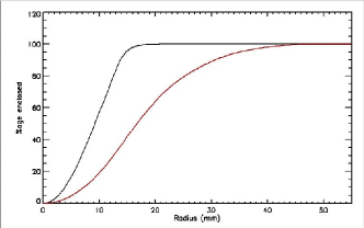
The disagreement between the measured and the expected PSF has also been obtained by comparing their radial profiles. The result is shown in Fig. 6. As it can be seen, the radius at which the expected cumulative distribution of the focused photons reach the saturation, corresponds to the radius at which 60% of the focused photons are collected.
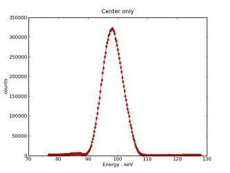
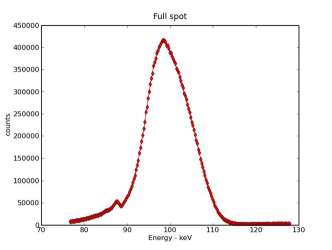
Also the spectrum of the developed PM has been measured. Given the distance of the diverging X–ray source and its distance from the lens, from the radius of the lens ring, the spectrum of the reflected photons is expected to show a peak around 100 keV. This indeed is what is found, as can be seen from Fig. 7, where we compare the measured spectrum of the central region (see black region in Fig. 5 with the spectrum of all reflected photons (see Fig. 4). As can also be seen from this figure, the centroid of the spectrum of the central region achieves an intensity level 0.8 times that of the peak spectrum of all reflected photons.
Also the effect of the temperature on the focusing properties of the lens have been investigated, finding a significant defocusing when the environment temperature has been decreased by 6 degrees with respect to the mean value (25.5 ∘C) at which the lens assembly procedure was performed.
5 Analysis of the results and work in progress
By shielding all the lens cystals but one, we have investigated the contribution of each lens crystal to the lens PSF and to the reflected photon spectrum. From these results, we have derived the positioning error of each crystal in the lens. In order to establish the true contribution of each assembling step to the cumulative error, we have performed further tests. In this way we have estimated the precision achieved in the single assembling steps.
From this analysis we have identified the likely origin of the positioning errors and established actions to be taken in order to remove them. We are now working to the improvement of the precision of the assembly steps. Also the quality of the mosaic crystals of Cu(111) will be improved, with the goal of building a new Laue lens prototype model in the second semester of this year.
Acknowledgements.
We acknowledge the financial support by the Italian Space Agency ASI and a minor contribution by the Italian Institute of Astrophysics (INAF). The design study was also possible thanks to the award of the 2002 Descartes Prize of the European Committee.References
- [1] Ubertini, P., Lebrun, F., Di Cocco, G., Bazzano, A., Bird, A. J., Broenstad, K., Goldwurm, A., La Rosa, G., Labanti, C., Laurent, P., Mirabel, I. F., Quadrini, E. M., Ramsey, B., Reglero, V., Sabau, L., Sacco, B., Staubert, R., Vigroux, L., Weisskopf, M. C., and Zdziarski, A. A., “IBIS: The Imager on-board INTEGRAL,” Astron. & Astrophys. 411, L131–L139 (2003).
- [2] Frontera, F., Costa, E., dal Fiume, D., Feroci, M., Nicastro, L., Orlandini, M., Palazzi, E., and Zavattini, G., “PDS experiment on board the BeppoSAX satellite: design and in-flight performance results,” in [EUV, X-Ray, and Gamma-Ray Instrumentation for Astronomy VIII, Oswald H. Siegmund; Mark A. Gummin; Eds. ], Siegmund, O. H. and Gummin, M. A., eds., Presented at the Society of Photo-Optical Instrumentation Engineers (SPIE) Conference 3114, 206–215 (Oct. 1997).
- [3] Knödlseder, J., von Ballmoos, P., Frontera, F., Bazzano, A., Christensen, F., Hernanz, M., and Wunderer, C., “GRI: focusing on the evolving violent universe,” in [Optics for EUV, X-Ray, and Gamma-Ray Astronomy III. Edited by O’Dell, Stephen L.; Pareschi, Giovanni. ], Presented at the Society of Photo-Optical Instrumentation Engineers (SPIE) Conference 6688, 5 (Sept. 2007).
- [4] Frontera, F., Pisa, A., de Chiara, P., and et al., “Exploring the hard X-/soft gamma-ray continuum spectra with Laue lenses,” in [ESA Special Publication ], Favata, F., Sanz-Forcada, J., Giménez, A., and Battrick, B., eds., ESA Special Publication 588, 323–+ (Dec. 2005).
- [5] Frontera, F., Pisa, A., Carassiti, V., Evangelisti, F., Loffredo, G., Pellicciotta, D., Andersen, K. H., Courtois, P., Amati, L., Caroli, E., Franceschini, T., Landini, G., Silvestri, S., and Stephen, J. B., “Gamma-ray lens development status for a European gamma-ray imager,” in [Space Telescopes and Instrumentation II: Ultraviolet to Gamma Ray ], Turner, M. J. L. and Hasinger, G., eds., Presented at the Society of Photo-Optical Instrumentation Engineers (SPIE) Conference 6266 (July 2006).
- [6] Knödlseder, J., “GRI: the gamma-ray imager mission,” in [Space Telescopes and Instrumentation II: Ultraviolet to Gamma Ray. Edited by Turner, Martin J. L.; Hasinger, Günther. Proceedings of the SPIE, Volume 6266, pp. 626623 (2006). ], Turner, M. J. L. and Hasinger, G., eds., Presented at the Society of Photo-Optical Instrumentation Engineers (SPIE) Conference 6266 (July 2006).
- [7] Frontera, F., Loffredo, G., Pisa, A., Milani, L., Nobili, F., Auricchio, N., Carassiti, V., Evangelisti, F., Landi, L., Squerzanti, S., Andersen, K. H., Courtois, P., Amati, L., Caroli, E., Landini, G., Silvestri, S., Stephen, J. B., Poulsen, J. M., Negri, B., and Pareschi, G., “Development status of a Laue lens project for gamma-ray astronomy,” in [Optics for EUV, X-Ray, and Gamma-Ray Astronomy III. Edited by O’Dell, Stephen L.; Pareschi, Giovanni. Proceedings of the SPIE ], Presented at the Society of Photo-Optical Instrumentation Engineers (SPIE) Conference 6688, 20 (2007).
- [8] Pellicciotta, D., Frontera, F., Loffredo, G., Pisa, A., Andersen, K., Courtois, P., Hamelin, B., Carassiti, V., Melchiorri, M., and Squerzanti, S., “Laue Lens Development for Hard X-rays (60 keV),” IEEE Trans. Nucl. Sci. 53, 253–258 (2006).
- [9] Courtois, P., Hamelin, B., and Andersen, K. H., “Production of copper and Heusler alloy Cu2MnAl mosaic single crystals for neutron monochromators,” Nuclear Instruments and Methods in Physics Research A 529, 157–161 (Aug. 2004).
- [10] Abrosimov, N. V., “Mosaic and gradient SiGe single crystals for gamma ray Laue lenses,” Experimental Astronomy 20, 185–194 (Dec. 2005).
- [11] Barriere, N., Developpement d’une lentille de Laue pour l’astrophysique nucleaire, PhD thesis, University of Toulouse, France (2008).
- [12] Pisa, A., Frontera, F., Loffredo, G., Pellicciotta, D., and Auricchio, N., “Optical properties of Laue lenses for hard X-rays (60 keV),” Experimental Astronomy 20, 219–228 (Dec. 2005).
- [13] Pisa, A., Frontera, F., De Chiara, P., Loffredo, G., Pellicciotta, D., Landini, G., Franceschini, T., Silvestri, S., Andersen, K., Courtois, P., and Hamelin, B., “Feasibility study of a Laue lens for hard x rays for space astronomy,” in [Advances in Computational Methods for X-Ray and Neutron Optics. Edited by Sanchez del Rio, Manuel. ], Sanchez del Rio, M., ed., Presented at the Society of Photo-Optical Instrumentation Engineers (SPIE) Conference 5536, 39–48 (Oct. 2004).
- [14] von Ballmoos, P., Halloin, H., Skinner, G. K., Smither, R. K., Paul, J., Abrosimov, N. V., Alvarez, J. M., Astier, P., Bastie, P., Barret, D., Bazzano, A., Boutonnet, A., Brousse, P., Cordier, B., Courvoisier, T., Di Cocco, G., Giuliani, A., Hamelin, B., Hernanz, M., Jean, P., Isern, J., Knödlseder, J., Laurent, P., Lebrun, F., Marcowith, A., Martinot, V., Natalucci, L., Olive, J.-F., Pain, R., Sadat, R., Sainct, H., Ubertini, P., and Vedrenne, G., “MAX: a gamma-ray lens for nuclear astrophysics,” in [Optics for EUV, X-Ray, and Gamma-Ray Astronomy. Edited by Citterio, Oberto; O’Dell, Stephen L. ], Citterio, O. and O’Dell, S. L., eds., Presented at the Society of Photo-Optical Instrumentation Engineers (SPIE) Conference 5168, 482–491 (Feb. 2004).
- [15] Loffredo, G., Frontera, F., Pellicciotta, D., Pisa, A., Carassiti, V., Chiozzi, S., Evangelisti, F., Landi, L., Melchiorri, M., and Squerzanti, S., “The Ferrara hard X-ray facility for testing/calibrating hard X-ray focusing telescopes,” Experimental Astronomy 20, 413–420 (Dec. 2005).