\runtitle2-column format camera-ready paper in LaTeX \runauthorS. Pepping
The ALICE detector and trigger strategy for diffractive and electromagnetic processes
Abstract
The ALICE detector at the Large Hadron Collider (LHC) consists of a central barrel, a muon spectrometer, zero degree calorimeters and additional detectors which are used for trigger purposes and for event classification. The main detector systems of relevance for measuring diffractive and electromagnetic processes are described. The trigger strategy for such measurements is outlined. The physics potential of studying diffractive and electromagnetic processes at the LHC is presented by discussing possible signatures of the Odderon.
1 The ALICE Experiment
The ALICE experiment is presently being built and commissioned at the Large Hadron Collider (LHC)[1, 2]. The ALICE experiment consists of a central barrel covering the pseudorapidity range and a muon spectrometer in the range . Additional detectors for trigger purposes and for event classification exist such that the range is covered. The ALICE physics program foresees data taking in pp and PbPb collisions at luminosities up to = and = , respectively. An asymmetric system pPb will be measured at a luminosity of = .
2 The ALICE Central Barrel
The detectors in the ALICE central barrel track and identify hadrons, electrons and photons in the pseudorapidity range . The magnetic field strength of 0.5 T allows the measurement of tracks from very low transverse momenta of about 100 MeV/c to fairly high values of about 100 GeV/c. The tracking detectors are designed to reconstruct secondary vertices resulting from decays of hyperons, D and B mesons. The granularity of the central barrel detectors is chosen such that particle tracking and identification can be achieved in a high multiplicity environment of up to 8000 particles per unit of rapidity. The main detector systems for these tasks are the Inner Tracking System, the Time Projection Chamber, the Transition Radiation Detector and the Time of Flight array. These systems cover the full azimuthal angle within the pseudorapidity range and are described below. Additional detectors with partial coverage of the central barrel are a PHOton Spectrometer (PHOS), an electromagnetic calorimeter (EMCAL) and a High-Momentum Particle Identification Detector (HMPID).
2.1 The Inner Tracking System
The Inner Tracking System (ITS) consists of six cylindrical layers of silicon detectors at radii from 4 cm to 44 cm. The minimum radius is determined by the beam pipe dimensions whereas the maximum radius chosen is determined by the necessity of efficient track matching with the outer detectors in the central barrel. The innermost layer extends over the range such that there is continous overlap with event classification detectors outside of the central barrel. Due to the high particle density of up to 80 particles/cm2 and in order to achieve the required tracking resolution, pixel detectors have been chosen for the first two layers. Silicon drift detectors are located in the middle two layers whereas double sided silicon strip detectors are in the outer two layers.
2.2 The Time Projection Chamber
The Time Projection Chamber (TPC) is the main tracking detector in the central barrel. The inner and outer radii of the active volume are 84.5 cm and 246.6 cm, respectively. The full radial track length is measured in the pseudorapidity range whereas tracks with at least one third of nominal radial length are covered in the pseudorapidity range . Particle identification is achieved by measuring the specific ionization loss. The chosen geometry results in a drift time of about 90 s. This long drift time is the factor limiting the proton-proton luminosity to the value mentioned above.
2.3 The Transition Radiation Detector
The principal goal of the Transition Radiation Detector (TRD) is to provide electron identification in the momentum range larger than 1 GeV/c. In this range, the electron identification by energy loss in the TPC is no longer sufficient. Since the TRD is a fast tracker, the TRD information can be used for an efficient trigger on high transverse momentum electrons. In addition, the position information from the TRD system improves the tracking performance of the central barrel.
2.4 The Time of Flight Detector
The Time-Of-Flight (TOF) array is located at a radial distance from 3.7 m to 4.0 m. The TOF information is used for particle identification in the range 0.2 GeV/c 2.5 GeV/c. For this detector, the Multi-gap Resistive-Plate (MRPC) technology was chosen. A strip with an active area of 120x7.4 cm2 consists of pads of 3.5 cm length and 2.5 cm width.
2.5 The Central Barrel Performance
2.5.1 Tracking Resolution
The ITS, TPC and TRD detectors described above are the main tracking detectors in the central barrel. With the information from these detectors, particles with momenta as low as 100 MeV/c can be tracked.
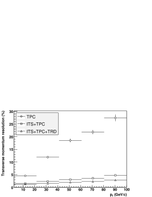
Fig.1 shows the transverse momentum resolution as expected from simulations. The TPC alone achieves a resolution of approximately 3% at a transverse momentum of = 10 GeV/c. Adding the information from ITS and TRD on the inner and outer side, respectively, improves the resolution considerably due to the increased leverage. The combined transverse momentum resolution from the ITS, TPC and TRD detector is expected to be about 3% at a transverse momentum of = 100 GeV/c.
2.5.2 Particle identification
Particle identification is achieved in the central barrel by different methods. First, the specific energy loss is measured by the TPC, the TRD and the strip and drift detectors of the ITS.
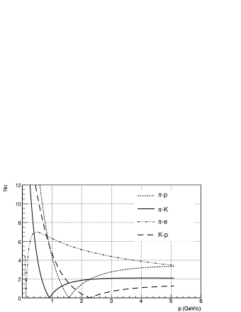
Fig.2 shows the combined particle identification capability by dE/dx measurement as a function of momentum. The separation of different particle species is shown in units of the resolution of the dE/dx measurement.
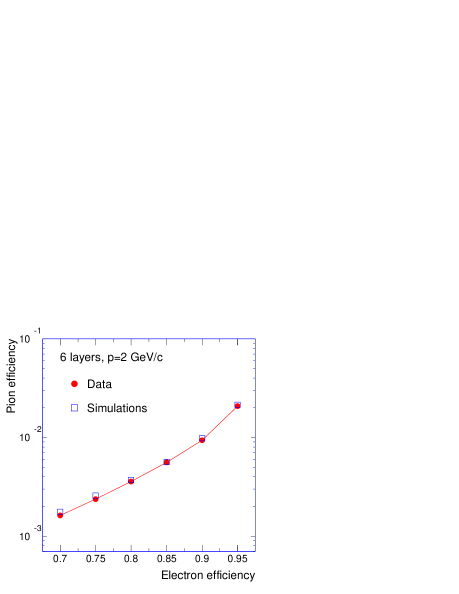
The electron-pion separation at high momenta is significantly improved by the information of the TRD system. Fig.3 shows the pion efficiency in the TRD as a function of the electron efficiency. Here, pion efficiency indicates that a pion is misidentified as an electron. The expected TRD performance for a full stack of six layers is shown by the squares and compared to test beam data represented by the circles.
3 The ALICE Zero Degree Neutron Calorimeter
The Zero Degree Neutron Calorimeters (ZDC) are placed on both sides of the interaction point at a distance of 116 m[3]. The ZDC information can be used to select different diffractive topologies. Events of the type do not deposit energy in these calorimeters, events will have energy in one of the calorimeters whereas events will have energy deposited in both calorimeters. Here, X denotes a centrally produced diffractive state from which the diffractive L0 trigger is derived as described below.
4 The ALICE diffractive gap trigger
Additional detectors for event classification and trigger purposes are located on both sides of the ALICE central barrel. First, an array of scintillator detectors (V0) is placed on both sides of the central barrel. These arrays are labeled V0A and V0C on the two sides, respectively. Each of these arrays covers a pseudorapidity interval of about two units with a fourfold segmentation of half a unit. The azimuthal coverage is divided into eight segments of 450 degrees hence each array is composed of 32 individual counters. Second, a Forward Multiplicity Detector (FMD) is located on both sides of the central barrel. The pseudorapidity coverage of this detector is and , respectively.
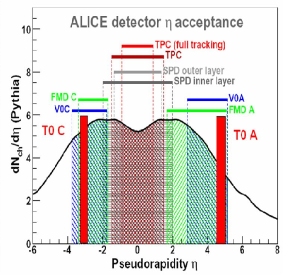
Fig.4 shows the pseudorapidity coverage of the detector systems described above. The geometry of the ALICE central barrel in conjunction with the additional detectors V0 and FMD is well suited for the definition of a rapidity gap trigger. The ALICE trigger system is designed as a multi-level scheme with L0,L1 and L2 levels and a high-level trigger (HLT). A central trigger processor (CTP) collects the information from the different detector systems and distributes the L0,L1 and L2 decisions back to the detectors. For L0 decision, the trigger information has to arrive at the CTP 850 ns after the interaction time. A rapidity gap trigger can be defined by the requirement of signals coming from the central barrel detectors while V0 and FMD not showing any activity. Such a scheme requires a trigger signal from within the central barrel for L0 decision. The pixel detector of the ITS system is suited for delivering such a signal[4].
The TRD detector system needs special consideration in the definition of a rapidity gap trigger. The TRD readout electronic is partly put in sleep mode after readout of an event in order to reduce power consumption. The TRD detector hence has its own pretrigger system which generates a wake up signal prior to an L0 decision from CTP. This pretrigger system has access to the information of the V0 detectors and generates wake up calls based thereupon. The V0 signal is, however, absent in a diffractive trigger. The pixel information described above is late for a diffractive TRD wake up call. Such a diffractive TRD wake up call can be generated based upon the information of the TOF detector. The information of the TOF array is forwarded to the TRD pretrigger system where multiplicity conditions and topological constraints are defined. In addition, the information of the V0 detectors is available at this level hence the rapidity gap width can be defined. The resulting L0 signal is fast enough to reach the CTP well before the time limit for L0 decision.
The high level trigger HLT has access to the information of all the detectors shown in Fig.4 and will hence be able to select events with rapidity gaps in the range and . These gaps extend over seven units of pseudorapidity and are hence expected to suppress minimum bias inelastic events by many orders of magnitude.
In addition to the scheme described above, the ALICE diffractive L0 trigger signal can be generated from the Neutron ZDC if no central state is present in the reaction. A L0 signal from ZDC does, however, not meet the 850 ns L0 time constraint described above. A L0 trigger from ZDC is therefore only possible during special data taking runs for which the 850 ns time limit is extended by about 150 ns. The possibility of such data taking is currently under discussion.
5 ALICE diffractive and electromagnetic physics
The tracking capabilities at very low transverse momenta in conjunction with the excellent particle identification make ALICE an unique facility at LHC to pursue a long term physics program of diffractive and electromagnetic physics. The low luminosity of ALICE as compared to the other LHC experiments restricts the ALICE physics program to reactions with cross section at a level of a few nb per unit of rapidity.
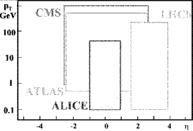
Fig.5 shows the transverse momentum acceptance of the four main LHC experiments. Not shown in this figure is the acceptance of the TOTEM experiment which has a physics program of measurements of total cross section, elastic scattering and soft diffraction[5]. The acceptance of the TOTEM telescopes is in the range of and . The combined data taking of TOTEM and CMS represents the largest rapidity interval covered at the LHC. The CMS transverse momentum acceptance of about 1 GeV/c shown in Fig.5 represents a nominal value. The CMS analysis framework foresees the reconstruction of a few selected data samples to values as low as 0.2 GeV/c[6].
6 Signatures of the Odderon
The Odderon was first postulated in 1973 and is represented by color-singlet exchange with negative C-parity[7]. Due to its negative C-parity, Odderon exchange can lead to differences between particle-particle and particle-antiparticle scattering. In QCD, the Odderon can be a three-gluon object in a symmetric color state. Due to the third gluon involved in the exchange, a suppression by the coupling is expected as compared to the two gluon Pomeron exchange. However, finding experimental signatures of the Odderon exchange has so far turned out to be extremely difficult[8]. A continued non-observation of Odderon signatures would put considerable doubt on the formulation of high energy scattering by gluon exchange[9]. The best evidence so far for Odderon exchange was established as a difference between the differential cross sections for elastic and scattering at = 53 GeV at the CERN ISR. The cross section displays a dip at t = -1.3 GeV2 whereas the cross section levels off. Such a behaviour is typical for negative C-exchange and cannot be due to mesonic Reggeons only.
6.1 Signatures of Odderon Cross Sections
Signatures of Odderon exchanges can be looked for in exclusive reactions where the Odderon (besides the photon) is the only possible exchange. Diffractively produced C-even states such as pseudoscalar or tensor mesons can result from photon-photon, photon-Odderon and Odderon-Odderon exchange. Any excess measured beyond the well understood photon-photon contribution indicates an Odderon contribution.
Diffractively produced C-odd states such as vector mesons can result from photon-Pomeron or Odderon-Pomeron exchange. Any excess beyond the photon contribution would be indication of an Odderon exchange.


Fig.6 shows the Feynman diagram for vector meson production by Pomeron-Odderon fusion with breakup of the protons on the left and without breakup on the right. The two different reaction channels can be identified by the information of the ZDC. To each of the two diagrams in Fig.6 exists a diagram in which the Odderon is replaced by a photon.
Cross sections for diffractively produced in pp collisions at LHC energies were first estimated by Schäfer et al[10]. More refined calculations by Bzdak et al result in a t-integrated photon contribution of 15 nb and a t-integrated Odderon contribution of 1 nb[11]. These two numbers carry large uncertainties, the upper and lower limit of these numbers vary by about an order of magnitude. This cross section is, however, at a level where in 106 s of data taking in ALICE the can be measured in its e+e- decay channel at a level of 4% statistical uncertainty. Due to the different t-dependence, the two contributions result in different distributions of the . The photon and Odderon contributions are shown in Fig.7 by the dotted and solid lines, respectively. A careful transverse momentum analysis of the might therefore allow to disentangle the Odderon contribution.

6.2 Signatures of Odderon Interference Effects
If the diffractively produced final state is not an eigenstate of C-parity, then interference effects between photon-Pomeron and photon-Odderon amplitudes can be analyzed.

Fig.8 shows the photon-Pomeron and the photon-Odderon amplitudes for production.
A study of open charm diffractive photoproduction estimates the asymmetry in fractional energy to be on the order of 15%[12]. The forward-backward charge asymmetry in diffractive production of pion pairs is calculated to be on the order of 10% for pair masses in the range [13, 14].
Acknowledgments
I thank Otto Nachtmann and Carlo Ewerz for illuminating discussions and Leszek Motyka for preparing and communicating Figure 7.
References
- [1] F. Carminati et al, ALICE Collaboration, 2004, J.Phys. G: Nucl. Part. Phys. 30 1517
- [2] B. Alessandro et al, ALICE Collaboration, 2006, J.Phys. G: Nucl. Part. Phys. 32 1295
- [3] R. Arnaldi et al, Nucl. Instr. and Meth. A 564 (2006) 235
- [4] The ALICE collaboration, ALICE experiment at the CERN LHC, accepted for publication in JINST
- [5] K. Eggert, TOTEM a different LHC experiment, CERN colloquium, feb 21,2008
- [6] D. d’Enterria et al, Addendum CMS technical design report, J. Phys. G34:2307-2455, 2007
- [7] L. Lukaszuk, B. Nicolescu, Lett. Nuovo Cim. 8 (1973) 406
- [8] C. Ewerz, Proceedings XII Rencontres de Blois (2005) 377
- [9] S. Donnachie, G. Dosch, P.V. Landshoff, O. Nachtmann, Pomeron physics and QCD, Cambridge University Press (2002) 297
- [10] A. Schäfer, L. Mankiewicz, O. Nachtmann, Phys.Lett. B 272 (1991) 419
- [11] A. Bzdak, L. Motyka, L. Szymanowski, J.R. Cudell, Phys.Rev. D 75 (2007) 094023
- [12] S.J. Brodsky, J. Rathsman, C. Merino, Phys.Lett. B 461 (1999) 114
- [13] P. Hägler, B. Pire, L. Szymanowski, O.V. Teryaev, Phys.Lett. B 535 (2002) 117
- [14] I.F. Ginzburg, I.P. Ivanov, N.N. Nikolaev, Eur.Phys.J. C5 (2003) 02