Further author information: (Send correspondence to F. Hormuth)
F. Hormuth: E-mail: hormuth@mpia.de, Telephone: +49 (0)6221 528 221
MicroLux: high-precision timing of high-speed photometric observations
Abstract
MicroLux is a GPS-based high precision and high speed timing add-on to the Calar Alto Lucky Imaging camera AstraLux. It allows timestamping of individual CCD exposures at frame rates of more than 1 kHz with an accuracy better than one microsecond with respect to the UTC timeframe. The system was successfully used for high speed observations of the optical pulse profile of the Crab pulsar in January and November 2007. I present the technical design concept of MicroLux as well as first results from these observations, in particular the reconstructed pulse profile of the pulsar111Based on observations collected at the Centro Astronómico Hispano Alemán (CAHA) at Calar Alto, operated jointly by the Max-Planck Institut für Astronomie and the Instituto de Astrofísica de Andalucía (CSIC)..
keywords:
low light level CCD, EMCCD, high speed photometry, GPS timing, pulsar timing1 INTRODUCTION
High spatial or spectral resolution observing techniques are nowadays a common standard at large modern optical telescopes. However, only few instruments exist that explore the temporal dimension with resolution higher than a few 10 Hz. On one hand, classical CCD imaging cameras have typical readout times of several ten seconds, resulting in increasingly small duty cycles if high temporal resolution is demanded. Cameras with fast readout capabilities on the other hand, e.g. frame transfer CCDs, suffer from increased readout noise, limiting the minimum brightness or exposure time significantly.
Nevertheless, high temporal resolution at optical wavelengths has its applications, especially in the near infrared (NIR), where sky brightness dominates the noise budget even at short exposure times. High speed photometry of stellar occultations by the moon, planets, or planetary rings and satellites, is a standard observing technique since several decades now. Typical instruments built for this purpose at visible wavelengths are based on photon counting Avalanche photodiodes[1, 2] or conventional CCDs using high readout clocks[3].
With the advent of electron multiplying CCDs (EMCCD) with virtually zero readout noise and single-photon detection capabilities at wavelengths below 1 m, high speed photometry of faint targets in the visible is now technically feasible even with medium sized telescopes, and with minimum technical effort. The Lucky Imaging camera AstraLux[4] at the Calar Alto 2.2-m telescope is such a system. Originally designed for high spatial resolution observations, the frame transfer EMCCD can be read out with frame rates of up 1.5 kHz, depending on binning and windowing settings. If all 512512 pixels of the 2424 arcsec large field of view are read unbinned, the resulting frame rate is still 34 Hz.
Unfortunately, high temporal resolution alone without precise knowledge of the absolute times of the individual measurements is not always sufficient. While the fringe pattern observed during a stellar occultation can be used to determine the star’s diameter on the basis of the known frame rate only, absolute timing is needed for precision measurements of e.g. eclipsing binary star parameters or the radio-optical delay of a pulsar. Decades ago, the signals of terrestrial navigation systems or television stations were used as time and frequency standards[6, 7]. Today, the Global Positioning System (GPS) satellite network is a powerful and reliable tool for absolute time measurements, and in fact GPS based timing solutions are employed in modern high speed photometry instruments.
 |
 |


|
Commercially available devices for GPS time tagging often allow for only low frame rates, not suitable for very high speed photometry, or were specifically designed for complex synchronisation tasks, and are quite expensive. In order to enable photometry at more than 1 kHz frame rate with sub-microsecond accuracy and at an affordable price, the MicroLux system was designed to enable precision time-tagging of individual frames taken with the AstraLux Lucky Imaging camera.
2 INSTRUMENT LAYOUT
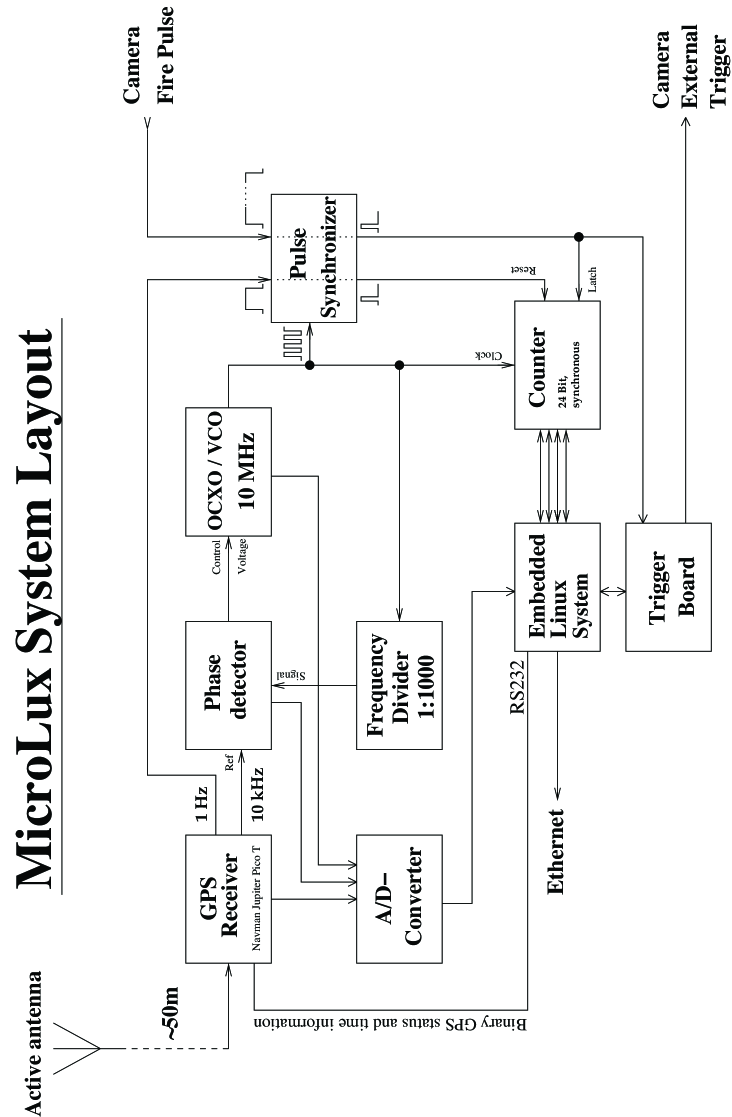
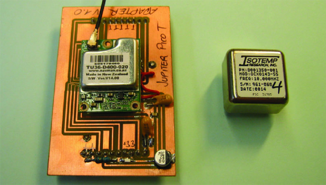
The layout of the AstraLux hardware is shown in Figure 1. The heart of the system is a commercial GPS receiver board, model Jupiter Pico T from Navman Ltd., UK (see Figure 2). After initial reception of at least four GPS satellites, the signal of a single satellite is sufficient to maintain a stable 1 Hz and 10 kHz signal, aligned to each other and with respect to the UTC second with an accuracy better than 30 ns. The Pico T module was especially designed for timing applications and assumes to be at a fixed location after establishing the initial 3D position.
Since MicroLux is physically located at the mirror cell of the telescope, but proper GPS reception is only possible outside the dome, a standard active GPS antenna is connected via 50 m of RG 213 coaxial cable and placed at one corner of the telescope building’s catwalk. This is sufficient to deliver good signal levels of usually 6–8 satellites not blocked by the metallic dome structure.
The GPS module’s 10 kHz output is further used to discipline the frequency and phase of an ovenised crystal oscillator (OCXO), model OCXO 143-55 by Isotemp Corp. (see Figure 2), via a phase locked loop (PLL) circuit. The OCXO alone is with a typical short-time frequency error of 1 Hz already very stable, and the PLL can thus work with a long time-constant of 10 s. Together with the time needed for warm-up of the OCXO and for the position fix of the GPS, the typical time until PLL lock is 4 min after system power-on. Given that MicroLux is switched on usually only once per observing run and then left running, this is more than acceptable.
For microsecond accuracy it would in principle be possible to use the OCXO tuned to 10 MHz in un-disciplined mode, since the frequency error would only sum up to a timing error less than 1 s until the next 1 Hz pulse of the GPS. However, by controlling the OCXO via the PLL, the VCO voltage becomes a powerful diagnostic tool. Any deviations from the regular mean value or increased noise are strong indicators for problems with the GPS’s timing accuracy, e.g. caused by a total loss of the satellite signal (see Figure 3) .
The GPS disciplined 10 MHz signal feeds a synchronous 24-Bit counter module, which is reset at every full UTC second by the GPS’s 1 Hz signal. At any given moment the counter value thus corresponds to the fraction of UTC second in units of 100 ns. An external signal, in this case the “Fire” pulse of the camera, rising at exposure start, latches the current counter value into three 8-Bit registers. The system’s control computer is notified via one of its I/O lines, reads out and saves the time tag of the last trigger event.
The control computer is an embedded Linux system running Kernel version 2.6, model “Foxboard LX” from Acme Systems, Italy. It provides various I/O lines, up to four serial ports, two USB ports, and a 100 MBit Ethernet interface. It establishes the connection between the counter hardware and the observatory’s computer network. A simple command line software is used to start time-tagging of a predefined number of events.
An 8-channel A/D converter with 12 Bit resolution is interfaced to the Linux board to allow monitoring of supply voltage levels, PLL parameters (VCO voltage, phase difference, oven current), and temperature in the system’s enclosure. Together with the GPS module’s status information received via one of the RS232 ports this provides full information about system health, GPS reception quality, and PLL lock status.
The CCD exposure start signal (the “Fire” pulse) is not directly fed into the counter module or Linux system, but first aligned with the 10 MHz signal and shortened to a length of 50 ns to avoid latch-up conditions and runt pulses in the subsequent stages. After passing this “Pulse Synchroniser” module it is fed into the trigger board. This is basically a flip-flop circuit, used to latch the exposure start signal and to indicate overflow conditions if a new start signal is received before the control computer was able to read out the timing information of the last one. This board also provides an output which can be used to trigger individual exposures of the camera or to start a free-running exposure sequence at a predefined time.
Special emphasis was put on using high-quality, linear low-noise power supplies for the GPS and PLL part, decoupled from the power supplies of the counter and Linux board. Together with the long time constant of the PLL, this leads to low phase noise of the GPS’s 10 kHz and the disciplined OCXO’s 10 MHz signals.
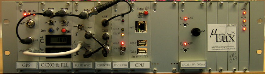
The complete system, shown in Figure 4, fits into a standard 19 inch electronics subrack, mounted in the electronics rack of the AstraLux camera. The weight is approximately 5 kg. Total hardware costs were below 1000 Euro, and the system could be developed and built by a single person in two months.
 |
2.1 Software
A cross-platform development kit allows to write software for the Foxboard control computer on any Linux PC. The compiled binary files are copied via FTP or SFTP to the target system.
The MicroLux software consists of a simple command line utilitiy. The program is invoked with the number of frames that will be acquired by the camera and a name for the logfile to be generated. Before any frames are acquired, the MicroLux software will synchronise itself with the UTC second pulses of the GPS system and obtain the full time and date information by decoding the binary data received from the GPS serial port. After synchronisation, the software waits for the next full UTC second to issue a start signal via the trigger board. This signal starts the free-running time-series acquisition of the AstraLux camera.
Each time the trigger board indicates the start of a new frame, the software reads out the counter value, i.e. determines the precise start time of the frame, and stores this information to the control computer’s RAM. It is checked and recorded if the trigger board has indicated an overrun condition.
Upon completion of the time series, all frame start times are written to the RAM file system, ready for retrieval via FTP or SFTP. A system health logfile is created, containing system voltage levels and GPS status information for a timespan of 10 s. Both files can be processed with own IDL programs, allowing to assess the quality of the timing information and to check for any anomalies.
A second command line tool continuously decodes the binary GPS status information and reads the A/D converter voltages. The values are displayed on the terminal screen, and any deviations from pre-defined expectations (e.g. due to problems with one of the power supply voltages, or anomalous GPS position measurements) are highlighted. This tool is mainly used during setup or at the begin of observing nights to get a quick and informative overview of the system’s health condition.
At the moment, this diagnostic tool cannot be run in parallel to the time-tagging software, since this has to be executed with high scheduler priority to allow time-tagging at kilohertz frame rates. A future version of MicroLux will use an FPGA circuit replacing the discrete counter and register module, employing a first-in-first-out storage register for up to 100 time-tagging measurements, leading to less strict demands on the Linux board’s real-time capabilities.


|
|
3 MEASUREMENTS AND OBSERVATIONS
3.1 Performance Checks
Before MicroLux was deployed at the telescope, laboratory tests were conducted to assess the reliability and accuracy of the system. A second GPS receiver, based on a Navman Ltd. Jupiter 12 module was used to generate trigger signals with precisely known frequencies. With a typical timing RMS of less than 50 ns, this module is comparable to the one used in MicroLux, and was actually used in an earlier version of the system. Up to 700000 time measurements of trigger signals with frequencies between 10 Hz and 1000 Hz, generated with the Jupiter 12 module, were acquired with MicroLux. This is the maximum number of events for which the timing information fits into the memory of the Foxboard Linux computer. In no case the difference between any two trigger signals in these series differed by more than 100 ns from the predicted value. This is the period length of the counter clock, and hence the expected measurement jitter. The statistical component of the measurement error can hence be assumed to be less than 0.1s. Including all delays in the electronics between signal input and counter module, the systematic delays were estimated as 300 ns. Using the 1 Hz second pulse as trigger signal, this delay was determined to be in fact 22020 ns. Even without a systematic correction of this delay by the software, the achieved timing acuracy of the MicroLux system is hence better than 1 s, the value adopted in the initial design considerations.
Tests with the AstraLux camera as source of the trigger pulses revealed that the frame rate as predicted by the camera software can differ by up to 0.5% from its actual value. The frame rate shows high stability, though, with quasi-periodic variations of the order of 10 ppm on scales of minutes (see Figure 5). They are probably related to temperature changes in the camera control computer housing, causing drifts of the camera control board’s master clock frequency. The periodicity most likely reflects the behaviour of the thermostat regulating the speed of the computer’s fan.
This shows that even for applications where absolute timing is not necessary, the MicroLux system is a valuable tool to determine at least the real frame rate. In the case of precise pulsar timing applications, measurements of the frame rate variations and the absolute frame start times are crucial.
3.2 Observations of the Crab Pulsar
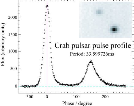
The Crab pulsar, PSR J0534+2200, has a period of 34 ms at an average optical magnitude of =16 mag. Time-resolved observations of its pulse profile were seen as an optimal test case for AstraLux & MicroLux, making full use of the camera’s single photon detection capability and the timing system’s accuracy.
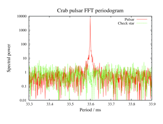
In January 2007, several millions of short exposure frames with integration times between 50 s and 2 ms were acquired in the , , , and filter, as well as unfiltered. Though this data is not completely reduced yet, early on-site analyses have proven that the instrument is able to reconstruct the pulse profile and to reliably reproduce the pulsar period as predicted by radio observations. The data will ultimately allow measurements of the radio-optical delay and its dependency on wavelength. Figure 6 shows a Fourier power spectrum of the photometry and the reconstructed pulse profile, generated from 700000 -band images with 1.6 ms single frame exposure time.
Before the pulse profile could be reconstructed, the pulsar period including corrections due to pulsar spindown and Doppler effects from earth rotation and earth’s orbital motion had to be determined to group the single images into phase bins. Instead of using a theoretical prediction, the period was measured in the optical data itself by using a phase dispersion minimisation (PDM) technique after a first guess of the period by FFT analysis.
The adopted period length was 0.03359972610-9 s. The radio-based theoretical prediction for the time and location of this observation was kindly computed by Michael Kramer of Jodrell Bank’s pulsar group: 0.03359972563 s. The difference between the two values is only 0.4 ns, well within the error bar estimated from the PDM algorithm. This corresponds to a relative accuracy of 10-7, or a phase error of 1∘ for the full 33600 pulsar periods that were covered by the data set used in this example. This result impressively confirms that MicroLux performs well and provides a valuable extension of AstraLux’s capabilities.
4 CONCLUSIONS
At total hardware costs of less than 1000 Euro and within less than two months of development time it was possible to design and built MicroLux, a high-speed, high-precision time-tagging system. Using a GPS disciplined ovenised crystal oscillator, MicroLux can determine the start times of individual CCD exposures with an accuracy better than 1 s at frame rates of more than 1000 Hz. Originally built for the Lucky Imaging camera AstraLux at the Calar Alto 2.2-m telescope, MicroLux could be used with other image acquisition systems as well thanks to its universal and modularised design.
MicroLux has been used mainly for observations of the optical pulse profile of the
Crab pulsar up to now, demonstrating that the intended design goals could be fully
reached. Further analysis will make use of the absolute timing capabilities of MicroLux
with respect to the UTC timeframe to determine the pulsar’s radio-optical delay and its
dependency on wavelength.
Other applications include precise timing of binary star eclipses or stellar occultations
by the moon, planets, planetary satellites, or asteroids.
Further planned improvements of MicroLux aim at increased versatility, higher maximum supported frame rates, and miniaturisation of the system, hopefully leading to a final design suitable for field-operation, e.g. in the case of stellar occultations by asteroids, where multiple observers with timing capabilities are needed to gather full information. The relatively simple design, based mainly on commercially available parts, and the low price are certainly great benefits in this respect.
References
- [1] Kanbach, G., Kellner, S., Schrey, F. Z., Steinle, H., Straubmeier, C., and Spruit, H. C., “Design and results of the fast timing photo-polarimeter OPTIMA,” in [Instrument Design and Performance for Optical/Infrared Ground-based Telescopes. ], Proc. SPIE 4841, 82–93 (2003).
- [2] Stefanescu, A., Kanbach, G., Słowikowska, A., Duscha, S., and Mühlegger, M., “OPTIMA-Burst: Observing GRB Afterglows and other Fast Transients with High Time Resolution,” in [High Time Resolution Astrophysics: The Universe at Sub-Second Timescales ], AIP Conference Series 984, 124–131 (2008).
- [3] Dhillon, V. S., Marsh, T. R., Stevenson, M. J., Atkinson, D. C., Kerry, P., Peacocke, P. T., Vick, A. J. A., Beard, S. M., Ives, D. J., Lunney, D. W., McLay, S. A., Tierney, C. J., Kelly, J., Littlefair, S. P., Nicholson, R., Pashley, R., Harlaftis, E. T., and O’Brien, K., “ULTRACAM: an ultrafast, triple-beam CCD camera for high-speed astrophysics,” MNRAS 378, 825–840 (2007).
- [4] Hormuth, F., “AstraLux: the Calar Alto Lucky Imaging Camera,” Proc. SPIE, this volume (2008).
- [5] Souza, S. P., Babcock, B. A., Pasachoff, J. M., Gulbis, A. A. S., Elliot, J. L., Person, M. J., and Gangestad, J. W., “POETS: Portable Occultation, Eclipse, and Transit System,” PASP 118, 1550–1557 (2006).
- [6] Papaliolios, C., Carleton, N. P., and Horowitz, P., “Absolute Time-of-arrival Measurements of Optical Pulses from the Crab Pulsar,” Nature 228, 445 (1970).
- [7] Lohsen, E. H. G., “Optical timing observations of the Crab pulsar 1968-1979,” A&AS 44, 1–14 (1981).