Quantum reflection of helium atom beams from a microstructured grating
Abstract
We observe high-resolution diffraction patterns of a thermal-energy helium-atom beam reflected from a microstructured surface grating at grazing incidence. The grating consists of 10-m-wide Cr strips patterned on a quartz substrate and has a periodicity of 20 m. Fully-resolved diffraction peaks up to the order are observed at grazing angles up to 20 mrad. With changes in de Broglie wavelength or grazing angle the relative diffraction intensities show significant variations which shed light on the nature of the atom-surface interaction potential. The observations are explained in terms of quantum reflection at the long-range attractive Casimir-van der Waals potential.
pacs:
03.75.Be, 34.35.+a, 37.25.+k, 68.49.BcOptical elements, such as mirrors and coherent beam splitters for matter waves, are prerequisite for atom and molecule interferometry. Both gratings formed by laser light and material gratings have been employed in Ramsey-Bordé and in Mach-Zehnder matter-wave interferometers, respectively Berman (1997). As the de Broglie wavelengths of atoms and molecules at thermal energies are typically nm, free-standing material transmission gratings of sub-micron periodicity had to be used in interferometers for beams of Na atoms Keith et al. (1991), dimers Chapman et al. (1995), and C60 fullerenes Brezger et al. (2002); Gerlich et al. (2007). In addition, diffraction by a 100-nm-period transmission grating was applied to quantitatively determine long-range atom-surface van der Waals potentials Grisenti et al. (1999); Brühl et al. (2002) and to investigate small He clusters Schöllkopf and Toennies (1994). Those gratings are, however, difficult to make, expensive, and fragile. Shimizu and coworkers demonstrated diffraction of ultracold atoms, released from a magneto-optical trap, by a 2-mm-period surface grating with reflective strips consisting of parallel 100-nm-wide ridges Shimizu and Fujita (2002a). Most recently, partially resolved diffraction peaks of thermal beams of metastable rare-gas atoms reflecting from a 2-m-period surface grating were reported Grucker et al. (2007).
Here, we present diffraction patterns of He atom beams that are coherently reflected from a home-made 20-m-period surface grating under grazing incidence. For incident grazing angles in the milliradian range the resulting diffraction angles are of the same order of magnitude as the ones observed with a 100-nm-period transmission grating at normal incidence Grisenti et al. (2000). The projection of the grating period along the incident beam direction yields an effective grating period in the sub-m range. Yet, a 20-m-period surface grating can readily be made out of a variety of materials using standard lithographic techniques. Unlike He atom beam scattering from smooth crystalline surfaces Hulpke et al. (1992), ultra-high vacuum and in-situ surface preparation are not needed, but coherent reflection is achieved with a microscopically rough surface.
We present evidence for the underlying coherent reflection mechanism being quantum reflection at the attractive long-range branch of the atom-surface interaction Friedrich et al. (2002). Quantum reflection from a solid surface was observed recently with ultracold metastable Ne Shimizu (2001) and He atoms Oberst et al. (2005), with a Bose-Einstein condensate Pasquini et al. (2006), and with a 3He atom beam Druzhinina and DeKieviet (2003). It was described theoretically in terms of the long-range Casimir-van der Waals atom-surface potential Friedrich et al. (2002). Furthermore, Shimizu and coworkers reported diffraction of ultracold metastable He atoms quantum-reflected from ridged surfaces Shimizu and Fujita (2002a, b).
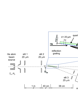
In the apparatus 111This apparatus was built at the Max-Planck-Institut für Strömungsforschung in Göttingen, Germany. a helium atom beam is formed by free-jet expansion of pure 4He gas from a source cell (stagnation temperature and pressure ) through a 5-m-diameter orifice into high vacuum. As indicated in Fig. 1 the beam is collimated by two narrow slits, each 20 m wide, located 15 cm and 115 cm downstream from the source. A third 25-m-wide detector-entrance slit, located 38 cm downstream from the grating, limits the angular width of the atomic beam to a full width at half maximum of 130 rad. The detector is an electron-impact ionization mass spectrometer that can be rotated precisely around the angle indicated in Fig. 1. The microstructured reflection grating is positioned at the intersection of the horizontal atom beam axis and the vertical detector pivot axis such that the incident atom beam impinges under grazing incidence (incident grazing angle mrad), with the grating lines oriented parallel to the pivot axis. The diffraction pattern is measured by rotating the detector around and measuring the mass spectrometer signal at each angular position.
The reflection grating consists of a 56-mm-long microstructured array of 110-nm-thick, 10-m-wide, and 5-mm-long parallel chromium strips on a flat quartz substrate. It was made from a commercial chromium mask blank by e-beam lithography. As shown in the inset of Fig. 1 the center-to-center distance of the strips, and thereby the period , is 20 m. Given this geometry the quartz surface between the strips is completely shadowed by the strips for all the incidence angles used. We expect a chromium oxide surface to have formed while the grating was exposed to air before mounting it in the apparatus where the ambient vacuum is about mbar. No in-situ surface preparation was done.
Fig. 2(a) shows a series of diffraction patterns measured at constant source conditions of K and bar corresponding to a de Broglie wavelength of Å. The incident grazing angle was varied between 3 and 15 mrad. The most intense peak in each diffraction pattern is attributed to the specular reflection (0th diffraction-order peak), for which the detection angle is equal to the incident grazing angle. The intensity of the specular peak decreases continuously from about 600 counts/s at mrad to only 13 counts/s at mrad. At mrad at least seven positive-order diffraction peaks can be seen at angles larger than the specular angle (diffraction ’away from’ the surface), while no negative diffraction-order peak is present. With increasing incident grazing angle negative-order diffraction peaks appear successively.
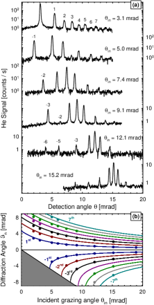
The diffraction angles are defined as the angular separation between the and diffraction-order peak, , and are analyzed in Fig. 2(b). It is straightforward to calculate the diffraction angles using the grating equation Born and Wolf (1959). Here is the angle (with respect to the grating surface plane) of the diffraction-order peak, and is the de Broglie wavelength. The calculated diffraction angles (lines in Fig. 2(b)) agree with the observed ones within the experimental error, thereby unambiguously confirming the interpretation of the peaks as grating-diffraction peaks. Note that with decreasing incidence angle the negative-order diffraction peaks disappear successively when the cut-off condition is met, i.e., when the peak is diffracted ’into the surface’. This regime is indicated by the grey-shaded region in Fig. 2(b).
The relative diffraction peak intensities change significantly with incident grazing angle. For instance, for mrad even and odd order peaks have similar heights falling off almost monotonously with increasing diffraction order. With increasing incident grazing angle, however, the positive even-order diffraction peaks tend to disappear. Moreover, a distinct peak-height variation can be seen for the -order peak which decreases sharply when is increased from to mrad.
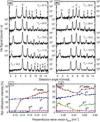
To investigate the origin of these peak-height variations we studied their dependence on the de Broglie wavelength by measuring two series of diffraction patterns at constant incident grazing angles of mrad and mrad (Fig 3). In each series we varied the source temperature and, hence, the de Broglie wavelength which is approximately proportional to Scoles (1988). The broadening of peaks at small is readily understood from Fig. 2(b) where it can be seen that a small width of the incident distribution leads to an increased width in due to the steep slope of the lines close to the cut-off.
To quantify the observed diffraction peak-height variations we determine the relative diffraction intensities from the area under each diffraction peak divided by the area of the corresponding -order peak. In Fig. 3(c) and (d) the relative diffraction intensities are plotted as a function of , the normal component of the incident wave vector (with the Boltzmann constant, the particle mass, and Planck’s constant over ). The plots reveal (i) pronounced variations of the diffraction intensities with for some diffraction orders, (ii) even-order diffraction intensities up to 18%, and (iii) significant asymmetries between corresponding positive and negative diffraction-order intensities. All three observations cannot be explained by the Fraunhofer-Kirchhoff diffraction theory which predicts the relative diffraction intensities for an amplitude grating to be independent of wavelength and to be determined by the ratio of grating period to strip width only Born and Wolf (1959). As this ratio is 2 for our grating, the even diffraction-order intensities are expected to vanish altogether. This behavior is indeed observed, but only in the limit of relatively large and as can be seen in Fig. 2.
We therefore attribute our observations to the long-range atom-surface interactions which have been observed previously in experiments with nanoscale transmission gratings Grisenti et al. (1999); Brühl et al. (2002); Perreault and Cronin (2005). For the reflection grating the relative diffraction intensities are expected to be an even more sensitive probe of the atom-surface interaction than for a transmission grating because every part of the atomic wavefunction probes the interaction potential. In addition, for sufficiently small angles above the surface the interaction path length is increased. A detailed theoretical model correctly accounting for the phase shift induced by the surface potential would be needed to determine the potential strength parameter from the data.
In Fig. 2 it can be seen that the peak heights decrease with increasing incident grazing angle. The total coherent reflection probability of the chromium strips is determined from the sum of all peaks normalized to the incident beam signal and multiplied by two to compensate for the 50% chromium coverage of the microstructure area. The reflection probability is as large as 40% at nm-1 and decreases continuously to less than 1% at nm-1 (Fig. 4). A kink at nm-1 separates a steep decay at smaller from a slow simple exponential decay at larger . The dependence on differs significantly from what is expected for specular reflection of a wave from a randomly-rough hard-wall surface at grazing incidence, which is given by , where denotes the root-mean-square roughness of the surface Beckmann and Spizzichino (1963). While this term does predict that even a rough surface reflects coherently in the limit , its dependence on exhibits the wrong curvature as displayed by the dash-dotted line in Fig. 4.
A better agreement is obtained when we assume quantum reflection at the long-range attractive branch of the atom-surface potential to be the mechanism for coherent reflection. We calculate the quantum reflection probability by numerically solving the 1-dimensional Schrödinger equation for an attractive Casimir-van der Waals surface potential of the approximate form . Here, denotes the distance from the surface, and the coefficient is the product of the van der Waals coefficient and a characteristic length ( nm for He) indicating the transition from the van der Waals () to the Casimir regime () Friedrich et al. (2002). For small (left to the kink in Fig. 4) good agreement with the data is found for Jm3. This value is slightly smaller than what is expected for He interacting with a transition metal surface ( Jm3) but larger than what is expected for an insulating surface Vidali et al. (1991). We attribute this behavior to an insulating chromium oxide surface having formed while the microstructure was exposed to air.
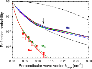
The kink and the slow decay at larger are not reproduced by this simple model. A similar kink was observed for He reflecting from a liquid He surface at nm-1 Nayak et al. (1983) and was explained by a quantum-reflection model based on a more realistic attractive potential shape Edwards and Fatouros (1978). As with increasing quantum reflection occurs at smaller Friedrich et al. (2002), the potential well region where the attractive branch deviates from a simple power law starts to influence the quantum-reflection probability. Our calculations indicate that this effect can be neglected only as long as nm-1 where we find agreement with the calculation.
Further support for quantum reflection is given by the observation of reflected beams of He trimers and Ne atoms. For He trimers ( K) the total coherent reflection probability increases by an order of magnitude to almost 10-2 when is lowered from 0.09 to nm-1 (Fig. 4). The data is modeled very well with a coefficient 3 times that used for the He monomer calculation, as one would expect for a van der Waals-bound cluster of 3 He atoms. The binding energy of the He trimer is only 11 eV Lewerenz (1997). Hence, it is more than three orders of magnitude smaller than the well depth of the estimated He3-surface potential. As a result, classical reflection at the potential’s repulsive inner branch should inevitably lead to dissociation.
For a Ne atom beam ( K) the observed reflectivity data is well matched by the calculated quantum-reflection probability for Jm3 (dashed line in Fig. 4, characteristic length nm). As in the case of He this coefficient is again somewhat smaller than expected for a transition metal ( Jm3 Vidali et al. (1991)).
In summary, we observed fully resolved diffraction peaks up to the order for a He atom beam reflected from a 20-m-period microstructured surface grating under grazing incidence. The observed relative diffraction intensities vary significantly with incident grazing angle and de Broglie wavelength. Furthermore, we observed coherent reflection probabilities from the surface grating for beams of Ne and of He3 as a function of the normal component of the incident wave vector. The measurements are in excellent agreement with the predictions from a simple 1-dimensional quantum-reflection model.
Acknowledgements.
B.S.Z. acknowledges support by the Alexander von Humboldt Foundation and by the Korea Research Foundation Grant funded by the Korean Government (KRF-2005-214-C00188). We thank R. Brühl for assistance with the data-acquisition software and H. Conrad and J.R. Manson for fruitful discussions.References
- Berman (1997) P. R. Berman, ed., Atom Interferometry (Academic Press, New York, 1997).
- Keith et al. (1991) D. W. Keith et al., Phys. Rev. Lett. 66, 2693 (1991).
- Chapman et al. (1995) M. S. Chapman et al., Phys. Rev. Lett. 74, 4783 (1995).
- Brezger et al. (2002) B. Brezger et al., Phys. Rev. Lett. 88, 100404 (2002).
- Gerlich et al. (2007) S. Gerlich et al., Nature Physics 3, 711 (2007).
- Grisenti et al. (1999) R. E. Grisenti et al., Phys. Rev. Lett. 83, 1755 (1999).
- Brühl et al. (2002) R. Brühl et al., Europhys. Lett. 59, 357 (2002).
- Schöllkopf and Toennies (1994) W. Schöllkopf and J. P. Toennies, Science 266, 1345 (1994); J. Chem. Phys. 104, 1155 (1996).
- Shimizu and Fujita (2002a) F. Shimizu and J. Fujita, J. Phys. Soc. Jap. 71, 5 (2002a).
- Grucker et al. (2007) J. Grucker et al., Eur. Phys. J. D 41, 467 (2007).
- Grisenti et al. (2000) R. E. Grisenti et al., Phys. Rev. A 61, 033608 (2000).
- Hulpke et al. (1992) E. Hulpke et al., eds., Helium atom scattering from surfaces (Springer, Berlin, 1992).
- Friedrich et al. (2002) H. Friedrich, G. Jacoby, and C. G. Meister, Phys. Rev. A 65, 032902 (2002).
- Shimizu (2001) F. Shimizu, Phys. Rev. Lett. 86, 987 (2001).
- Oberst et al. (2005) H. Oberst et al., Phys. Rev. A 71, 052901 (2005).
- Pasquini et al. (2006) T. A. Pasquini et al., Phys. Rev. Lett. 97, 093201 (2006).
- Druzhinina and DeKieviet (2003) V. Druzhinina and M. DeKieviet, Phys. Rev. Lett. 91, 193202 (2003).
- Shimizu and Fujita (2002b) F. Shimizu and J. Fujita, Phys. Rev. Lett. 88, 123201 (2002b).
- Born and Wolf (1959) M. Born and E. Wolf, Principles of Optics (Pergamon Press, London, 1959).
- Scoles (1988) G. Scoles, ed., Atomic and Molecular Beam Methods (Oxford University Press, Oxford, 1988).
- Perreault and Cronin (2005) J. D. Perreault and A. D. Cronin, Phys. Rev. Lett. 95, 133201 (2005).
- Beckmann and Spizzichino (1963) P. Beckmann and A. Spizzichino, The Scattering of Electromagnetic Waves from Rough Surfaces (Pergamon Press, London, 1963).
- Vidali et al. (1991) G. Vidali et al., Surf. Sci. Rep. 12, 135 (1991).
- Nayak et al. (1983) V. U. Nayak, D. O. Edwards, and N. Masuhara, Phys. Rev. Lett. 50, 990 (1983).
- Edwards and Fatouros (1978) D. O. Edwards and P. P. Fatouros, Phys. Rev. B 17, 2147 (1978).
- Lewerenz (1997) M. Lewerenz, J. Chem. Phys. 106, 4596 (1997).