Thermal depinning of fluxons in discrete Josephson rings
Abstract
We study the thermal depinning of single fluxons in rings made of Josephson junctions. Due to thermal fluctuations a fluxon can be excited from its energy minima and move through the array, causing a voltage across each junction. We find that for the initial depinning, the fluxon behaves as a single particle and follows a Kramers-type escape law. However, under some conditions this single particle description breaks down. At low values of the discreteness parameter and low values of the damping, the depinning rate is larger than the single particle result would suggest. In addition, for some values of the parameters the fluxon can undergo low-voltage diffusion before switching to the high-voltage whirling mode. This type of diffusion is similar to phase diffusion in a single junction, but occurs without frequency-dependent damping. We study the switching to the whirling state as well.
I Introduction
In past years many works have been devoted to the study of extended discrete nonlinear systems. On the one hand, it is important to deepen our knowledge of general properties of such systems since they often have application to many different physical situations. On the other hand, many physical systems are well described by nonlinear discrete models. In this field, the emergence of the concept of soliton for instance (in the continuous and its discrete counterparts) was paradigmatic. Rem94 ; Sco03 A well known example of model system supporting this type of nonlinear excitations is the discrete Sine-Gordon equation (also called Frenkel-Kontorova model). BK98 ; BK04 ; Flo96
A Josephson-junction (JJ) array is by construction a discrete system made of interacting nonlinear solid state devices. JJ arrays are an example of physical systems with great fundamental and technological interest which are well described by discrete nonlinear models. Lik86 ; Tin96 From the experimental point of view, Josephson junctions are a privileged place to study solitons and to explore their possible applications. Ust98
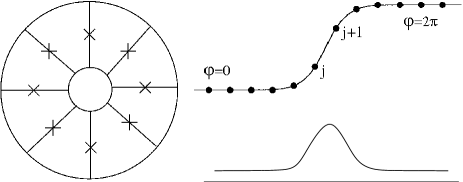
Of the many different geometries for a JJ array the so-called Josephson ring (a set of JJ connected in parallel and closed forming a ring, see Fig. 1) is well described by a discrete sine-Gordon equation and supports nonlinear discrete solitons or kinks, usually called fluxons in this context. Wat95b Thus, many studies of the discrete sine-Gordon equation or the role of kinks in nonlinear arrays have direct application when studying JJ rings. Conversely the study and modelization of JJ rings allows exploration of new issues concerning the behavior of these nonlinear phenomena.
Our model system is the so-called Josephson ring, a collection of JJ coupled in parallel and forming a ring (see figure 1). When cooled below the superconducting critical temperature an integer number of magnetic flux quanta, fluxons, can be trapped in the ring. Then, the physical properties of the array are dominated by the presence of the fluxons in the system. The I-V curve of the array shows the mean voltage across the array as a function of a constant external current applied to every junction of the array. When current is applied, the array remains superconducting up to a certain critical value which defines the critical current of the array. In the presence of fluxons this current corresponds to the fluxon depinning current. At this current, the fluxon starts to move around the array and finite voltage is measured.
In many cases the energy exchange between the system and the environment is relevant, so thermal fluctuations have to be considered. Tin96 Because of this, at finite temperature the value of the depinning current and the shape of the I-V curve can be strongly affected by thermal fluctuations. Motivated by recent experiments on the thermal depinning and dynamics of fluxons (kinks) in small rings made of 9 junctions, Ken08 in this work we numerically explore some of these issues. In addition, in some cases the fluxons can be understood as particles on a substrate periodic potential.
The main object of this paper is to study numerically the thermal depinning of a single fluxon in a JJ ring and compare it with numerical simulations and analytical predictions for the case of a single particle. We have found excellent agreement in many cases. However, under some conditions the single particle description fails. In addition, for some values of the parameters the fluxon can undergo low-voltage diffusion before switching to the high-voltage whirling mode. This type of diffusion is similar to phase diffusion in a single underdamped junction, but occurs without frequency-dependent damping.
II Equations
Josephson junctions are made of two superconducting materials separated by a thin insulating barrier. Driven by an external current, this system behaves as a solid-state nonlinear oscillator and is modeled by the same dynamical equations that describe a driven pendulum: Tin96 . Here , the variable that describes the behavior of the junction, is the gauge-invariant phase difference of the superconducting order parameter at both sides of the junction. In this equation current is normalized by the junction critical current and time by the junction plasma frequency ( is the magnetic flux quantum and the junction capacitance). is an important parameter which measures the dissipation in the system (, with the effective resistance of the junction). The last term, , describes the effect of thermal noise in the dynamics (Johnson current noise) and satisfies and where we use for a normalized temperature (with the Josephson energy . The normalized dc voltage which gives the response of the system to the external current is defined by .
As previously stated, the JJ ring consists of a series of individual junctions connected in parallel. Such system can be though of as a series of coupled pendula. Following the usual model for the system, the equations for an array made of coupled junctions driven the same external current are given by: Wat95b
| (1) |
Index denotes different junctions and run from to . The new parameter accounts for the coupling between the junctions which, in the framework of this model, occurs between neighbors and has an inductive character , with the self inductance of every cell in the array. Boundary conditions are defined by the topology of the array (here we consider circular arrays) and the number of trapped fluxons in the system: .
In this article we will consider the case of a single fluxon. We have studied different sizes for the array, but here we will present results for an array made of 9 junctions, similar to those being experimentally studied. We will also study different values of and restrict our interest to underdamped arrays biased by a dc current in a broad range of temperatures.
III Results
In this section we are going to present numerical simulations of the dynamics of one fluxon in a Josephson ring and one particle in a periodic potential. We will also show numerical calculations from single particle thermal escape theory.
III.1 I-V curves: damping regimes
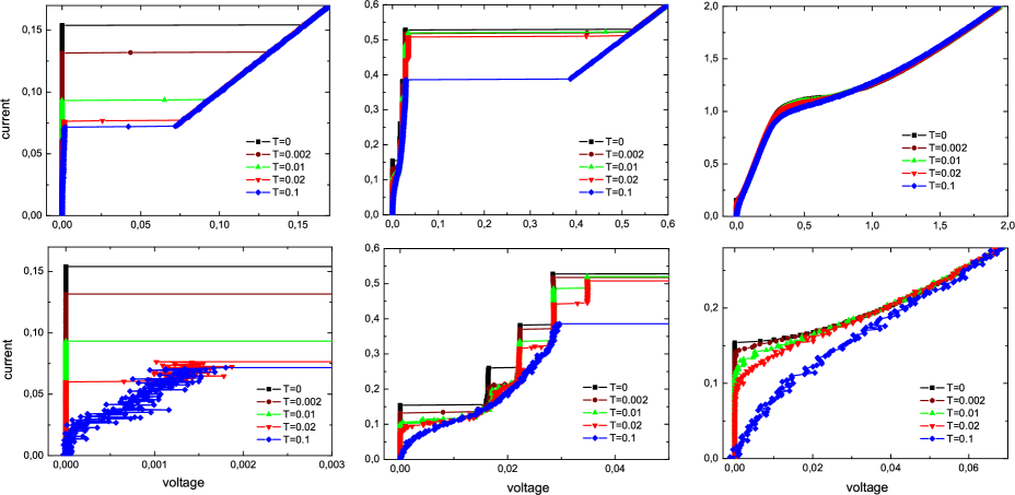
Figure 2 shows single I-V curves for one fluxon in a 9 junctions Josephson ring with . In this case the width of the fluxon is close to 2, so it is well localized in the array and discreteness effects are important. disc Curves were simulated at three different values of damping and five temperatures. Current was increased from zero to some maximum at an average ramp equal to in normalized units.
Let us look first at the curves. If we start at zero bias, in all the cases the fluxon is pinned to the array up to the so-called depinning current is reached (for , ). Above this current very different I-V characteristics are observed depending on the value of the damping.
At small damping the system switches from the state to a high-voltage ohmic state () where all the junctions rotate uniformly (whirling branch). The damping is so small that when the fluxon moves through the array it excites all the junctions to the high-voltage state. In this voltage state the fluxon is totally delocalized in the array. For clarity, we have shown only curves for increasing current. If current is decreased from the high-voltage state the junctions retrap at a small value of the current (mostly defined by ). The curve is hysteretic and shows bistability for a wide range of currents.
At intermediate values of damping the dynamics is much more complex. Now the I-V curve shows a low-voltage region dominated by a series of steps which correspond to resonances between the fluxon velocity and the linear modes of the array. These resonances has been the object of great attention in the past. Ust93 ; Van95 ; Ust95 ; Wat95 ; Wat95b ; Zhe98 ; Pfe08 For these currents the fluxon moves around the ring in a localized manner. This regime persists up to a given value of the current for which the fluxon reaches a high velocity and all the junctions switch to the high-voltage part of the curve. At moderate damping the IV curve can also be multistable with hysteresis loops on every step.
At high values of the damping dissipation governs the dynamics, multistability disappears and the voltage increases from zero without discontinuities and jumps as soon as current reaches the depinning value. In this part of the curve a localized fluxon is moving around the ring and voltage is related with the fluxon velocity. For currents close to 1 (in normalized units) it starts the transient to another regime where the fluxon delocalizes and all the junctions rotate and contribute to the overall voltage in the array. Flo96
Figure 2 also shows the dynamics of the array in the presence of thermal noise. As can be seen in the figure, the first thermal effect is that the fluxon depins at smaller currents. For small damping we find that if temperature is high enough, noise also induces a fluxon diffusion branch, which we discuss later in the paper. At moderate damping, the low-voltage resonances are rounded and at high enough temperature voltage increases smoothly from zero to some value on the fluxon diffusion branch, and then switches to the high-voltage region of the I-V curve. At high damping temperature causes a rounding of the curve.
We will study how temperature affects the I-V curve at low damping since this is the case for the experimental system we are trying to model. Usually the depinning current is experimentally defined as the current for which measured voltage is above a certain threshold. We have followed the same definition in our simulations. This is a good definition in the low damping and low temperature regime where the system switches between two very different voltage values so a threshold independent current is expected. However, the election of the threshold voltage is not trivial. A small threshold can give problems at large temperatures where voltage fluctuations are also large. A large threshold is not a good choice since ignore possible low-voltage states like the fluxon diffusion one. If low-voltage states are present we distinguish between the depinning current and the switching current , where depinning marks the end of the superconducting state and switching the transition to the high-voltage branch. At very high temperatures noise can reach the threshold level and first switching is suppressed. To study this issue we have used in our simulation three or five different thresholds and compare results for all of them.
III.2
The depinnig current is a stochastic variable with a given probability distribution. We present results for the mean value of the depinning current and its standard deviation . Results were obtained after the numerical simulation of the dynamical equations of the system for 1000 samples. We used different values of damping (typically from 0.001 to 0.1) and coupling (usually from 0.2 to 1.0). The number of junctions in the array is . Another important parameter of the simulations is the current ramp; in our case this ramp change from one simulation to other but it is of the order of .
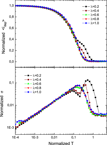
Figure 3 shows results for and five different values of the coupling ( and ). The main physical properties of the fluxon in the array change importantly with the value of . Thus, the zero temperature depinning current of the array decreases a factor of 30 from to (see table below). In order to compare the five curves, in figure 3 both axis have been scaled by the value of the zero temperature depinning current for every case. comment1 We see that once scaled all curves are similar showing that in this range of parameters these results can be understood in a unified manner.
In the figure we see that decreases to zero as effect of temperature. All the curves follow the same behavior but at high temperatures the small curves slightly deviates from the others. For temperatures of the order of the barrier thermal fluctuations dominate the dynamics and the depinning current goes to zero. In fact, at high temperatures there is no a good definition of depinning current since different thresholds may give different results. With respect to the standard deviation, we can see that it grows with as predicted by standard thermal activation theory and reaches a maximum at high temperatures, when has an inflection point, close to . Then the standard deviation decreases since all escape events happens in a narrow range of current values.
III.3 The fluxon as a single particle.
When studying the dynamics of one fluxon in the array it is very common to use the picture of this extended and collective object as a single particle. BK98 ; BK04 ; Mar97 ; Cat01 This approach has been extensively used in the past and, as we will see, it is very useful although not exact.
Let us consider a new variable representing the center of masses of the fluxon or the position of the fluxon in the array. Then, in the simplest approach, the dynamics of a fluxon in a ring can be approach by the dynamics of a driven, damped, massive particle experiencing a sinusoidal substrate potential (Peierls-Nabarro potential) and subjected to thermal fluctuations:
| (2) |
where
| (3) |
In this simple approach we are neglecting for instance the spatial dependence of the mass, effective damping due to the other degrees of freedom of the system and higher order terms in the expansion of the substrate potential for the fluxon.
Table 1 gives a relation of numerically computed values of some of the parameters of the fluxon and its effective potential in the single particle picture: is the zero current potential barrier; is the squared frequency for small amplitude oscillations of the fluxon around equilibrium; is the fluxon effective mass at rest (computed as ) and the depinning current. For a perfect sinusoidal potential we should get . The exact results are close to it.
| 0.2 | 0.77842 | 0.77405 | 0.5028 | 0.38482 |
|---|---|---|---|---|
| 0.4 | 0.30974 | 0.44775 | 0.3459 | 0.15435 |
| 0.6 | 0.12744 | 0.23151 | 0.2757 | 0.06367 |
| 0.8 | 0.05539 | 0.11721 | 0.2363 | 0.02767 |
| 1.0 | 0.02550 | 0.06041 | 0.2110 | 0.012725 |
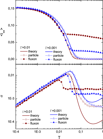
Figures 4 and 5 show for and respectively (in both cases ) the comparison between the results for the fluxon in the array, numerical simulations of the depinning of a single particle in a sinusoidal potential (Eq. 2) and a theoretical calculation based on analytical results for the thermal activation rate of particles in sinusoidal potentials in the low damping regimen. Ful74 ; Mar87 ; BHL83 ; Mel86 ; Han90 ; Mel91 In the figure we plot the result computed from the Büttiker, Harris and Landauer equation for escape rate at [Eq. (3.11) in reference BHL83 ]. We have checked that a very close result (indistinguishable at the scale of the figure) is got when using 1.47 or the Melnikov and Meshov theory. Mel86
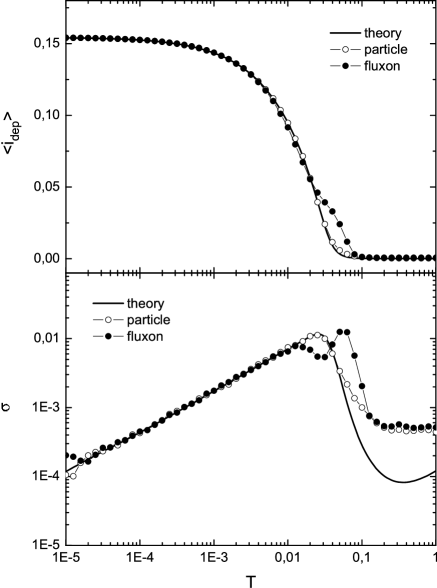
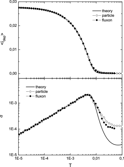
We can see that the single particle simulations reproduce the results for the fluxon in an excellent way at this value of the damping in all the temperature range although a small deviation in a range of temperatures is observed for . Theoretical estimations disagree at high values of since escape rate equations were obtained in the infinite barrier limit ().
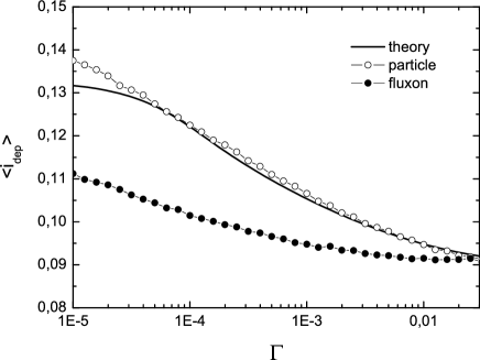
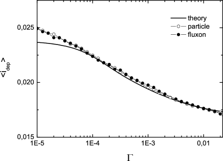
The agreement shown in Figures 4 and 5 does not occur for other values of coupling and damping. For instance, for and (figure 9 below) a deviation of the simulated curve with respect to the theoretical prediction is found. To study further such result we have done numerical simulations at fixed for different values of and for () and (). comment3 Results are shown in figures 6 and 7. There we can see that for the fluxon results deviate importantly from the expected for the single particle (or the theory) when damping is decreased. However this is not the case for . In this respect it seems to be important the degree of discreteness of the system. Such degree is measured by the coupling parameter (high approach the continuum limit of the system, and small increases the discreteness effects). At small values of effects due to other degrees of freedom are more important and if damping is small such excitations persist longer in the system.
III.4 Fluxon diffusion
In figure 2 we have seen that at low damping and high enough temperature a low-voltage branch appears in the curves before the escape to the full running state. In this low-voltage state, the transport of the fluxon occurs through a series of noise-induce phase slips (or depending on the definition of the fluxon center of masses) where every jump corresponds to a fluxon which advances one cell in the array. Such state can not be understood in terms of the single particle picture. In analogy with the phase diffusion that occurs in a single junction, we label this mode of transport fluxon diffusion. In spite of the fact of we are in the low damping regime, the fluxon is able to travel along the ring without exciting the whirling branch. Remarkably this is a thermally excited state and it is not seen at low temperatures.
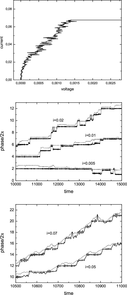
In figure 8 we show the time evolution of the phase of one junction (junction 1) and a phase associated with the center of mass of the fluxon defined as to allow a better comparison. Current values have been chosen in the low-voltage branch The random jumps of for the junction or for the fluxon phase are easily observed.
We have also done numerical experiments to simulate the jump from the diffusion branch to the full whirling state. These simulations are done with a higher voltage threshold, but are otherwise similar to the previous experiments. Results for and are shown in figure 9, here . We see that theory and single particle results agree quite well in all the range. At high temperature thermal fluctuations dominate, are of the order of the barrier, and theoretical results do not apply. We also see that the standard deviation increases with temperature following the expected law up to a certain value where reaches a maximum and then decreases when is close to zero.
However, in figure 9 we can also see that for the fluxon curve there exists a value of such that at higher temperatures, the value of the current for which the array switches to the whirling branch is temperature independent. This temperature shows the emergence of a fluxon diffusion branch in the I-V curve. Looking at curves it appears that the switching current value is defined by some value of the fluxon velocity. Comparing the standard deviation curve in figure 9 to the similar one with the lower threshold in figure 4, as expected, we can see that a peak occurs much earlier in temperature for the jump from the diffusion state.
IV Discussion and Conclusions
We have studied the thermal depinning of fluxons in small Josephson rings at small values of damping. At zero temperature as current is increased the system switches from a superconducting zero voltage state to a resistive state where . This happens at the so called depinning current. Beyond this current there is not static configuration for one fluxon in the array, and the fluxon starts to move. Due to the low value of the damping when fluxon goes through the array causes all the junctions to switch to a high-voltage state. Then all the junctions do the same but with a phase difference that accounts for the presence of one quantum of flux homogeneously distributed along the whole array.
Due to thermal fluctuations, in an experiment the value of the measured depinning current changes from one I-V to another and only a probability distribution function has sense. This function is usually characterized by its mean value and its standard deviation. The main object of this paper has been to numerically study how these observables behave for different system parameters (coupling , damping and temperature ). cr We also have compared these results with numerical simulations and theoretical estimations for the depinning of a single particle in a sinusoidal potential.
As expected, the mean value of the depinning or the switching current decreases as temperature is raised. At low temperatures the standard deviation follows the usual law. At higher temperatures the function reaches a peak, that we can identify with the points on the or curves at which the curvature changes sign (inflection point).
Roughly speaking our results show that the depinning of the fluxon can be understood in terms of the stochastic dynamics of a single particle in a tilted sinusoidal potential. However, we have seen some unexpected effects that we attribute to discreteness. Then for the case of small coupling ( and smaller) we have seen an increasing deviation of the fluxon depinning behavior from our expectations from the single particle picture. Arrays with a larger coupling are closer to the continuous limit and discreteness effects are smaller; here the single particle picture works much better.
The other effect we have observed is the emergence at small damping of a low-voltage thermally excited state that we call fluxon diffusion. In such cases the zero temperature I-V curve does not show any resonance or low-voltage state and the system switches from zero voltage to the high-voltage branch. However, after some temperature a low-voltage branch is observed. The system first switches from zero to this branch and then to the high-voltage state. At higher temperatures the system first continuously increases voltage from zero (then is not clear how to define ) and at larger currents switches from the low-voltage state to the high-voltage one. We have also seen that the values of damping and current for which this behavior is observed depends importantly in and also in the number of junctions in the array, . N
An important point of our work has been to compare our numerical results with results based on the single particle picture. The main conclusion is that for most of the cases this picture gives a good estimation of the fluxon depinning current. In fact, in an experimental case, where the different parameters (mainly , and ) are known with some imprecision will be difficult to identify deviations from the expected behavior. In addition, there are some points difficult to address: the effective one-dimensional potential for the fluxon in the array (Peierls-Nabarro potential) is not purely sinusoidal, and the value of the fluxon mass is not constant since it depends on the fluxon position and the current value. We are also neglecting all the system degrees of freedom except one and we know that in some cases this is not valid: for instance, to understand resonant steps which are due to coupling between the fluxon velocity and the linear waves of the discrete array or to understand the fluxon diffusion branch. We have also considered the expression for the escape rate in a multidimensional case. In this expression usually the attempt frequency depends on the frequency of all the stable modes in the minimum and the saddle. Han90 We have computed such numbers and check that the maximum error is smaller of (and occurs for ).
Our numerical results for the single particle agree pretty well the predictions from Kramers theory for escape rate except for some limits. Disagreement at high temperatures is expected since theoretical expressions are computed in the infinite barrier limit of the system (). This limit is not fulfilled at high temperatures. This is also true at small temperatures, where most of the escape events occur at currents very close to where the barrier is also very small. We have checked that the ratio in this case is also small. To finish we have to mention the unexpected disagreement at small values of . We are currently study further such results.
In the single-particle picture, or the RCSJ model for a single junction, it has become generally accepted that diffusion cannot coexist with hysteresis. This was elucidated nicely in Kautz and Martinis Kau90 through phase space arguments. Simply put, if the value of applied current is sufficient to allow a stable running state to coexist with the fixed points of zero voltage, the basins of attraction for that running state necessarily separates the basins of attraction for any two neighboring fixed points. Phase jumps between two fixed points are thus forbidden, as the system must first pass through the basin of attraction for the running state. While we have shown in previous sections that the initial escape of the fluxon from its minima can be explained by thermal activation of a single particle, the fluxon diffusion state in the I-V curves of figure 2 cannot be explained in a similar way.
In the original single-junction experiments on phase diffusion, the coexistence of phase diffusion and hysteresis was explained by the presence of frequency-dependent damping from the junction leads. A simple model of frequency-dependent damping is a series-RC circuit in parallel with the junction, which adds an extra degree of freedom to the phase space for the junction dynamics. This extra dimension resolves the above-mentioned issue regarding the non-overlapping basins of attraction. A main result of the paper is the observation of fluxon diffusion in our simulations without frequency dependent-damping, which has not been included in our equations. Instead of the extra dimension introduced by frequency-dependent damping, fluxon diffusion must occur because of the additional degrees of freedom from the multiple junctions in the array. We plan to explore the physics of this new diffusion mechanism in future experiments and simulations.
When studying the behavior of the system at different temperatures we have seen that the mean value of the distribution of the switching current from the fluxon diffusion branch is almost constant and the standard deviation is very small. Comparing the standard deviation curve in figure 9 to the similar one with the lower threshold in figure 4, we also see that a peak occurs much earlier in temperature for the jump from the diffusion state. This peak in the standard deviation is also reminiscent of experiments on single junctions, Kiv05 ; Kras05 ; Man05 where a peak in the standard deviation indicated the collapse of thermal activation and the onset of diffusion.
To finish we want to mention that to our knowledge there are not experimental or numerical results studying systematically the thermal escape of fluxons or solitons in discrete arrays. However we want here to mention the work by A. Wallraff et al on vortices in long JJ. Wallraff With respect with theoretical advances we want also to cite recent work Sbo07 where major differences between the macroscopic quantum tunnelling in JJ from tunnelling of a quantum particle are reported.
Acknowledgments
We acknowledge F. Falo for a carefully reading of the manuscript. Work is partially supported by DGICYT project FIS2005-00337 and NSF Grant DMR 0509450.
References
- (1) M. Remoissenet, Waves Called Solitons: Concepts and Experiments (Springer, Berlin, 1994).
- (2) A. C. Scott, Nonlinear Science: Emergence and Dynamics of Coherent Structures, 2nd ed. (Oxford University Press, Oxford, 2003).
- (3) O. M. Braun, and Y. S. Kivshar, Phys. Rep. 306, 1 (1998).
- (4) O. M. Braun, and Y. S. Kivshar, The Frenkel-Kontorova Model. Springer, 2004.
- (5) L. M. Floría, and J. J. Mazo, Adv. Phys. 45, 505 (1996).
- (6) K. K. Likharev, Dynamics of Josephson Junctions and Circuits (Gordon and Breach, New York, 1986).
- (7) M. Tinkham, Introduction to Superconductivity, 2nd ed. (McGraw-Hill, New York, 1996).
- (8) A. V. Ustinov, Physica D 123, 315 (1998).
- (9) S. Watanabe, H. S. J. van der Zant, S. H. Strogatz, and T. P. Orlando, Physica D 97, 429 (1995).
- (10) K. Segall et al, unpublished.
- (11) The existence of a depinning current is also a discrete effect (breaking of fluxon translational symmetry). The depinning current rapidly approaches to zero when increases and we approach the continuous limit of the system.
- (12) A. V. Ustinov, M. Cirillo, and B. A. Malomed, Phys. Rev. B 47, 8357 (1993).
- (13) H. S. J. van der Zant, T. P. Orlando, S. Watanabe, and S. H. Strogatz, Phys. Rev. Lett. 74, 174 (1995).
- (14) A. V. Ustinov, M. Cirillo, B. H. Larsen, V. A. Oboznov, P. Carelli, and G. Rotoli, Phys. Rev. B 51, 3081 (1995).
- (15) S. Watanabe, S. H. Strogatz, H. S. J. van der Zant, and T. P. Orlando, Phys. Rev. Lett. 74, 379 (1995).
- (16) Z. Zheng, B. Hu, and G. Hu, Phys. Rev. B 58, 5453 (1998).
- (17) J. Pfeiffer, A. A. Abdumalikov, M. Schuster, and A. V. Ustinov, Phys. Rev. B. 77 024511 (2008).
- (18) The physical reason for such scaling is based in the normalization of equation (2).
- (19) P. J. Martínez, F. Falo, J. J. Mazo, L. M. Floría, and A. Sánchez, Phys. Rev. B. 56, 87 (1997).
- (20) C. Cattuto, G. Costantini, T. Guidi, and F. Marchesoni, Phys. Rev. B 63 094308 (2001).
- (21) T. A. Fulton, and L. N. Dunkleberger, Phys. Rev. B. 9 4760 (1974).
- (22) J. M. Martinis, M. H. Devoret, and J. Clarke, Phys. Rev. B 35 4682 (1987).
- (23) M. Büttiker, E. P. Harris, and R. Landauer, Phys. Rev. B 28, 1268-1275 (1983).
- (24) V. I. Mel’nikov, and S. V. Meshkov, J. Chem.Phys. 85 1018 (1986).
- (25) P. Hänggi, P. Talkner, and M. Borkovec, Rev. Mod. Phys. 62, 251 (1990).
- (26) V. I. Mel’nikov, Phys. Rep. 209, 1 (1991).
- (27) This value is given by H. Risken and K. Voigtlaender, J. Stat. Phys. 41, 825 (1985). It also corresponds to the number which at low damping gives the better agreement between the Büttiker, Harris and Landauer equation and the Mel’nikov and Meshkov one.
- (28) Note that the ratio is the same for both cases.
- (29) This value also depend on the current ramp which enters into the equations in a way well established by theory.
- (30) This paper only shows results for 9 junctions arrays. However, we have done also numerical simulations for larger arrays.
- (31) R. L. Kautz, and J. M. Martinis, Phys. Rev. B 42, 9903 (1990).
- (32) J. M. Kivioja et al., Phys. Rev. Lett. 94, 247002 (2005).
- (33) V. M. Krasnov et al., Phys. Rev. Lett. 95, 157002 (2005).
- (34) J. Männik et al., Phys. Rev. B. 71, 220509(R) (2005).
- (35) A. Wallraff et al., Nature 425, 155 (2003) and Rev. Scientific Instruments 74, 3740 (2003).
- (36) A. O. Sboychakov et al, Europhys. Lett. 80, 17009 (2007).