Observation of inter-Landau-level quantum coherence in semiconductor quantum wells
Abstract
Using three-pulse four–wave–mixing femtosecond spectroscopy, we excite a non–radiative coherence between the discrete Landau levels of an undoped quantum well and study its dynamics. We observe quantum beats that reflect the time evolution of the coherence between the two lowest Landau level magnetoexcitons. We interpret our observations using a many-body theory and find that the inter–Landau level coherence decays with a new time constant, substantially longer than the corresponding interband magnetoexciton dephasing times. Our results indicate a new intraband excitation dynamics that cannot be described in terms of uncorrelated interband excitations.
pacs:
78.47.nj, 42.50.Md, 73.20.Mf, 78.67.DeQuantum coherences between discrete states, formed by creating a superposition with well-defined relative phase, are central for manipulating matter on a quantum level and can provide the basis of schemes for information processing. Raman coherences in atomic systems lead to non–linear optical effects with potential technological importance, such as electromagnetically induced transparency and lasing without inversion. eit For applications, it is desirable to observe and manipulate analogous coherences in semiconductors. Quantum beats due to coherence between heavy and light hole valence band states, inter-val as well as collective excitations in the quantum Hall system QHE and spin excitations in quantum dots, QD have been reported. Standard two–pulse four–wave–mixing (FWM) experiments do not access directly the Raman coherence, which can be inferred by simultaneously measuring the pump–probe signal p-p or by using three–pulse wave–mixing. cundiff ; QHE Recently, Spivey et. al. cundiff demonstrated faster dephasing of the coherence between heavy and light hole excitons than the corresponding interband dephasing.

Here we create and study long–lived coherence between magnetoexcitons in semiconductor quantum wells (QWs), which we control with a perpendicular magnetic (B) field. The QW confinement discretizes the eigenstates along the z–axis (growth direction). The B–field results in quasi-confinement within the x–y plane, thus discretizing the eigenstates into Landau levels (LL). Continuum states are suppressed and the resulting discrete spectrum can be tuned with the B–field. Such effective zero–dimensional confinement opens new possibilities for creating and manipulating coherence. Long-lived intraband coherences could be useful in future applications of quantum technology. Also, understanding the coherence dynamics in QWs subject to a B–field is a necessary step towards a comprehensive picture of the quantum dynamics in the quantum Hall effect regime.QHE ; perakis
In semiconductors, the Coulomb interaction leads to effects such as exciton-exciton correlations, Ultra1 ; Ultra2 ; kner while exciton coupling to the environment gives both dephasing and new coherences.DCTS In many–body systems, it is not easy to treat such complex correlations theoretically. perakis Thus, the measurement of quantities that characterize the coherence dynamics gives valuable information on the non–equilibrium properties of complex systems.
Here we investigate the dynamics of interaction–induced inter–LL coherence in an undoped QW subject to a large B–field. We photoexcite X0 and X1 magnetoexcitons (Xn consists of an electron in the -th conduction-band LL and a hole in the -th valence-band LL, Fig. 1a) and create a XX1 coherence, X01 (Fig. 1b). We identify a three-pulse FWM signal that reflects the dynamics of X01 and displays quantum beats with a new decay time. Using a many-body theory, perakis we identify the source of these beats and extract the dephasing rate of X01. We find that, unlike for uncorrelated magnetoexcitons, this rate is substantially smaller than the sum of the magnetoexciton dephasing rates.
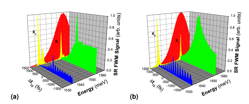
We study a ten well, undoped GaAs QW structure, with 14 nm thick GaAs layers sandwiched between 10 nm thick layers of Al0.3Ga0.7As. The sample is kept at 1.5-4∘K in a split-coil magneto-optical cryostat. A B–field (B=0-7 T) is applied along the QW growth direction. We excite the sample with three fs pulses of right-circularly polarized () light (Fig. 1c). These pulses propagate along directions , , and , with a time delay () between pulse and (). For negative values of the above delays, pulse arrives first. We study the transient signal in the background free direction . Using an interference filter, we spectrally resolve this signal and separate the X0 and X1 responses. We measure the signal intensity from each state (spectrally resolved FWM) as function of and . As explained below, the axis () accesses the dynamics of the intra–band coherence, while the axis measures the interband polarization dephasing.
Fig. 1d shows a schematic of the FWM signal due to the X01 coherence along the negative axis. To contribute in the direction, the inter–LL excitation X01 must be created by either and or and pulses. In Fig. 1d, pulses and arrive together (), and create the X01 coherence, which evolves for a time before it is probed by pulse . During this time interval, the coherence accumulates a phase at frequency and decays with a rate , both reflected in the FWM dependence on ( is the energy of Xn). Thus, for , we can access the X01 coherence dynamics, while, for , pulse arrives first and the FWM signal reflects the dynamics of the interband polarization created by .
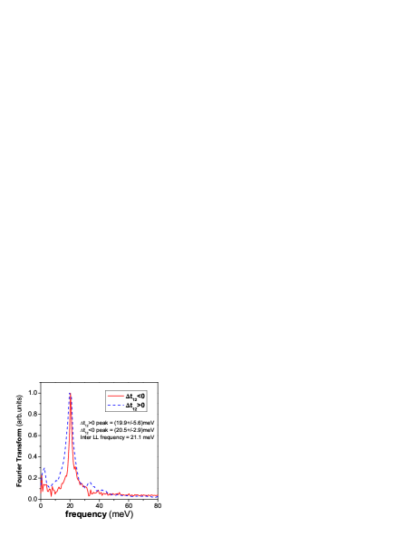
Fig. 2a shows the FWM intensity from both X0 and X1 along the axis. We largely excite X1 over X0 (see backpanel of Fig. 2) in order to suppress the Pauli blocking [phase space filling (PSF)] contribution at X0. We then see a very small X0 signal (as compared to X1) with striking beats. As discussed above, the negative and positive axes reflect different dynamics, so we analyze the decay rates separately. We subtract a constant (exponential) background from the negative (positive) axis and take the Fourier transform of the resulting signal (Fig. 3). In both cases, we see a strong peak at energy , where and are obtained from the linear absorption spectrum (back panel of Fig. 2a). However, we see a large difference in the linewidths obtained by fitting a Lorentzian to the peaks: 2.9 meV for the negative side vs. 5.6 meV for the positive. Therefore, the beats decay slower for . This asymmetric decay allows us to identify the decoherence time.
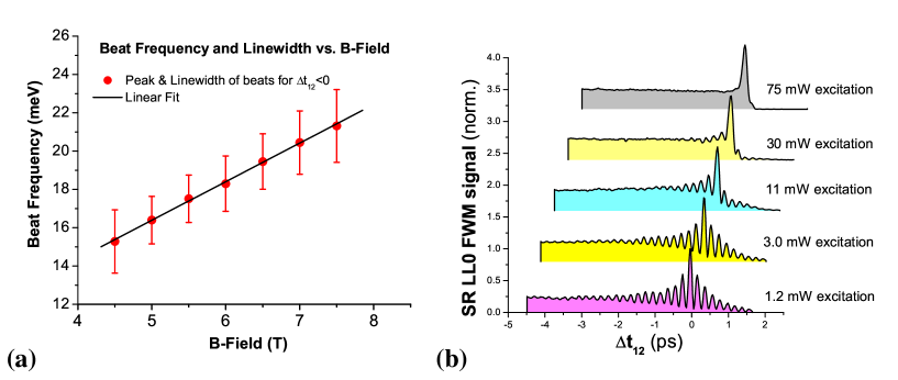
Fig. 4a shows the beat frequencies and linewidths extracted from the X0 FWM signal along the negative axis for various B–fields. We see a linear dependence of the beat frequency on B, as expected for large B–fields (where the cyclotron energy exceeds the Coulomb energy x-x ; shah ) from the inter–LL energy . From the slope of Fig. 4a we extract an e–h reduced mass of 0.0580.001, which, for electron mass of 0.066, corresponds to the heavy–hole mass of 0.498. On the other hand, we do not observe any substantial linewidth changes with B. We also studied the changes in the X0 FWM signal for increasing photoexcitation intensity (Fig. 4b). The decoherence times decrease as the photoexcited carrier density increases, while the asymmetric beat decay and overall temporal profile remain the same.
We analyze our results using a many-body theory perakis based on the dynamics controlled truncation scheme (DCTS). DCTS We expand in terms of the optical field in order to decrease the number of independent dynamical variables and separate out the correlated contributions to the third–order non–linear optical response. We consider optical pulses and include for simplicity only the photoexcited X0 and X1 states. We use the standard Hamiltonian that treats the Coulomb interactions between carriers in a B–field. perakis For polarized light, the only dipole–allowed optical transition is from the (, ) valence band into the (1/2,-1/2) conduction band.fromer This, as well as the measured linear dependence of the beat frequency on the B–field, allows us to consider a simple two band semiconductor model and assume the heavy hole mass of 0.498.
The FWM signal from Xn is described by the polarization . We derive the following equation of motion for (ignoring the non-resonant terms):
| (1) | |||||
where and are the energy and dephasing rate of X0, the interband transition matrix element, the optical pulse, the X0–X1 interaction,perakis the linear Xn polarization, the X01 Raman coherence, and the incoherent Xn density. The second term on the right hand side (rhs) of Eq. (1) is due to PSF. The last two terms, due to the Coulomb interaction , give a nonlinear coupling of X0 and X1. Setting recovers the semiconductor Bloch equations in a magnetic field.x-x We ignored the bi–magnetoexciton correlations shah ; perakis since our FWM signal along the negative axis, generated by these correlations, kner ; shah is suppressed and decays fast.
The DCTS showed that, in the absence of correlations mediated by a bath, the dynamics can be described in terms of interband amplitudes only. DCTS It is then impossible to obtain lifetimes longer than the magnetoexciton dephasing times. Here the key variable is ,DCTS ; perakis
| (2) |
which evolves with frequency and decays with rate (as in the interval of Fig. 1d). The second (source) term is due to the coupling to a bath, characterized by dephasing rates.DCTS It arises when the X01 dephasing rate, , deviates from the sum of the Xn dephasing rates, . In the case of uncorrelated interband transitions, the inter–LL coherence is given by the magnetoexciton amplitude product , which decays with a rate . This Hartree–Fock result gives the third term on the rhs of Eq.(1).x-x implies correlations, mediated by the bath, between the interband transitions. The dynamics of intraband and interband coherences can then be distinguished.
A microscopic calculation of and requires complete knowledge of the coupling to the bath. Ref.[perakis, ] analyzed the Coulomb coupling to a cold electron gas. Ref.[DCTS, ] demonstrated different time evolution of inter–band and intra–band variables due to exciton–phonon dynamics. In our system, dephasing arises from the interplay between phonon–carrier and carrier–carrier scattering and the disorder, which breaks the LL degeneracy, leading to a finite LL width. A complete theory of this interplay is lacking at present. However, our results clearly show different time evolution of Xn and X01 due to the bath.
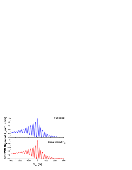
The numerical solution of our full equations, including nonresonant contributions, gives the FWM signal of Fig. 2b. This reproduces the experimental features. The signal due to the term in Eq.(1) reflects the phase accumulated by during , while the term gives , where is the relaxation rate of the incoherent X1 population. We attribute our long–lived coherence to the beating of the two above contributions, with frequency , which decays at a rate of . All other FWM contributions lead to oscillations that decay as or faster. On the other hand, for positive , all beatings have frequency and decay as . explanation This is illustrated in Fig. 5: without the contribution, the oscillations for both positive and negative decay with ; however, including with , the oscillations decay more slowly on the negative axis. With increasing photoexcited carrier density, carrier–carrier scattering enhances and , so the quantum beats decay faster as the intensity increases (Fig. 4b). However, the overall FWM temporal profile remains unchanged, reflecting population relaxation with very small . We extract from the oscillation decay an inter–LL coherence dephasing rate of meV. Our work demonstrates tunable quantum dynamics between Coulomb–coupled discrete Landau levels.
This work was supported by the Office of Basic Energy Sciences of the US Department of Energy and by the EU STREP program HYSWITCH.
References
- (1) K. J. Boller, A. Imamoglu and S. E. Harris, Phys. Rev. Lett. 66, 2593 (1991); A. S. Zibrov, M. D. Lukin, D. E. Nikonov, L. Hollberg, M. O. Scully, V. L. Velichansky, and H. G. Robinson, Phys. Rev. Lett. 75 1499 (1995).
- (2) M. E. Donovan, A. Shülzgen, J. Lee, P.-A. Blanche, N. Peyghambarian, G. Khitrova, H. M. Gibbs, I. Rumyantsev, N. H. Kwong, R. Takayama, Z. S. Yang, and R. Binder, Phys. Rev. Lett. 87, 237402 (2001); K. B. Ferrio and D. G. Steel, Phys. Rev. Lett. 80, 786 (1998); M. Joschko, M. Woerner, T. Elsaesser, E. Binder, T. Kuhn, R. Hey, H. Kostial, and K. Ploog, Phys. Rev. Lett. 78, 737 (1997); T. Dekorsy, A. M. T. Kim, G. C. Cho, S. Hunsche, H. J. Bakker, H. Kurz, S. L. Chuang, and K. Köhler, Phys. Rev. Lett. 77, 3045 (1996).
- (3) K. M. Dani, J. Tignon, M. Breit, D. S. Chemla, E. G. Kavousanaki, and I. E. Perakis, Phys. Rev. Lett. 97, 057401 (2006); N. A. Fromer, C. E. Lai, D. S. Chemla, I. E. Perakis, D. Driscoll, and A. C. Gossard, Phys. Rev. Lett.89, 067401 (2002).
- (4) M. V. Gurudev Dutt, J. Cheng, B. Li, X. Xu, X. Li, P. R. Berman, D. G. Steel, A. S. Bracker, D. Gammon, S. E. Economou, R.-B. Liu, and L. J. Sham, Phys. Rev. Lett. 94, 227403 (2005).
- (5) S. A. Hawkins, E. J. Gansen, M. J. Stevens, A. L. Smirl, I. Rumyantsen, R. Takayama, N. H. Kwong, R. Binder, and D. G. Steel, Phys. Rev. B 68, 035313 (2003).
- (6) A. G. VanEngen Spivey, C. N. Borca, and S. T. Cundiff, Solid State Commun. 145, 303 (2008).
- (7) A. T. Karathanos, I. E. Perakis, N. A. Fromer, and D. S. Chemla, Phys. Rev. B 67, 035316 (2003); I. E. Perakis and E. G. Kavousanaki, Chem. Phys. 318, 118 (2005); K. M. Dani, E. G. Kavousanaki, J. Tignon, D. S. Chemla, and I. E. Perakis, Solid State Commun 140, 72 (2006).
- (8) D. S. Chemla and J. Shah, Nature 411, 549 (2001).
- (9) W. Schäfer and M. Wegener, Semiconductor Optics and Transport Phenomena (Springer, Berlin, 2002).
- (10) P. Kner, S. Bar–Ad, M. V. Marquezini, D. S. Chemla, and W. Schäfer, Phys. Rev. Lett. 78, 1319 (1997).
- (11) V. M. Axt, K. Victor, and A. Stahl, Phys. Rev. B 53, 7244 (1996); V. M. Axt and S. Mukamel, Rev. Mod. Phys. 70, 145 (1998).
- (12) C. Stafford, S. Schmitt–Rink, and W. Schaefer, Phys. Rev. B 41, 10000 (1990).
- (13) T.V. Shahbazyan, N. Primozich, and I. E. Perakis, Phys. Rev. B 62, 15925 (2000).
- (14) N. A. Fromer, C. Schüller, C. W. Lai, D. S. Chemla, I. E. Perakis, D. Driscoll, and A. C. Gossard, Phys. Rev. B 66, 205314 (2002).
- (15) When (and ), pulse arrives first. It creates a polarization that evolves for time with frequency and decay rate , until pulses and come in. Different processes can then take place, but the FWM signal emitted in the direction will only depend on as . Thus, the only oscillations that can be created beat with frequency and decay as .