Penetration Depth of Transverse Spin Current in Ferromagnetic Metals
Abstract
The line width of the ferromagnetic resonance (FMR) spectrum of Cu/CoFeB/Cu/Co/Cu is studied. Analyzing the FMR spectrum by the theory of spin pumping, we determined the penetration depth of the transverse spin current in the Co layer. The obtained penetration depth of Co is 1.7 nm.
Index Terms:
Ferromagnetic resonance, Spin Pumping, Transverse Spin Current, Gilbert dampingI Introduction
There is great interest in the field of current-driven magnetization dynamics (CDMD) because of its potential applications to non-volatile magnetic random access memory and microwave devices. The concept of CDMD was first proposed by Slonczewski [1] and independently by Berger [2] in 1996. In the last decade, many experimental studies have shown the evidences of CDMD [3],[4].
Theoretical studies of CDMD have also been developped [5],[6]. The origin of the CDMD has been understood as the transfer of spin angular momentum of the conducting electrons to the magnetization of the ferromagnetic metal. One of the most important quantities in CDMD is the penetration depth of the transverse (perpendicular to the magnetization) spin current , over which the transfer of spin angular momentum is achived. However, there is a controversial issue regarding the penetration depth of the transverse spin current. The ballistic theory of electron transport argues that is on the order of the lattice constant in conventional ferromagnets such as Fe, Co and Ni, and their alloys [7],[8]. On the other hand, the Boltzmann theory of electron transport argues that is on the order of a few nm [9],[10],[11]. However, only a few experimental measurements of the penetration depth has been reported [12],[13].
In our previous paper [14], we studied the line width of the ferromagnetic resonance (FMR) spectrum in a ferromagnetic(F)/nonmagnetic(N) metal five-layer system (N1/F1/N2/F2/N3), and showed that the line width of the F1 layer depends on the thickness of the F2 layer due to spin pumping [15],[16]. Analyzing the FMR spectrum, the penetration depth of the transverse spin current of NiFe, CoFe and CoFeB were obtained [14]. Our result seems to support the Boltzmann theory of electron transport. However, we cannot compare our results with the results of [9],[10],[11] directly since only the penetration depth of Co is studied in [9],[10],[11]. In this paper, we study the line width of FMR spectrum of Cu/CoFeB/Cu/Co/Cu five-layer system, and determine the penetration depth of Co. The obtained penetration depth of Co, 1.7 nm, has good agreement with the results of [9],[10],[11].
II Theory
Spin pumping [15],[16] is, in some sense, the reverse process of CDMD, where the precession of the magnetization in the ferromagnetic layer generates spin current flowing into the adjacent layers. In a ferromagnetic/nonmagnetic metal multi-layer system the Gilbert damping constant of the ferromagnetic layer is enhanced due to spin pumping. Analyzing the dependence of the Gilbert damping on the thickness of the nonmagnetic layer the spin diffusion length, i.e., the penetration depth of spin current in the nonmagnetic layer is determined.
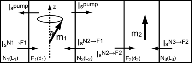
The penetration depth of the transverse spin current of a ferromagnetic metal, , is also determined in a similar way. Let us consider N1/F1/N2/F2/N3 metal five-layer system shown in Fig. 1, where () is the unit vector along the magnetization of the -th ferromagnetic layer. The magnetization of the F1 layer () is in resonance with the oscillating magnetic field, and pumps spin current flowing into the other layers. The precession axis of is along the direction of the magnetization of the F2 layer (). Since the magnetization vector of is perpendicular to [14] and the precession angle is very small (about 1 deg), the dominant component of the magnetization vector of spin current flowing into the F2 layer is perpendicular to , i.e., the dominant component of the spin current flowing into the F2 layer is the transverse spin current. Thus, analyzing the dependence of the FMR spectrum of the F1 layer on the thickness of the F2 layer, the penetration depth of the transverse spin current of the F2 layer can be determined. However, the conventional theory of spin pumping assumes that the penetration depth of the transverse spin current is zero. Thus, we need to extend the theory of spin pumping by taking into account the finite penetration depth [14].
The spin current pumped from the F1 layer is given by [15]
| (1) |
where is the Dirac constant and is the real (imaginary) part of the mixing conductance. The pumped spin current creates spin accumulation in the other layers. The spin accumulation is given by
| (2) |
where is the Pauli matrix and is the non-equilibrium distribution matrix in spin space. In general, the distribution matrix of a ferromagnetic layer, , is given by , where is the unit matrix, is the non-equilibrium charge distribution and is the difference in non-equilibrium distribution between spin-up ( and spin-down () electrons. () is a set of orthogonal unit vectors in spin space where is the unit vector parallel to the magnetization vector. and are the non-equilibrium distribution of the transverse spin components. Spin accumulation in a nonmagnetic layer is defined in a similar way.
The spin accumulation induces a backflow of spin current. The backflow of spin current flowing from the Ni layer to the Fk layer is expressed in terms of the spin accumulation as
| (3) |
where and are the spin accumulation of the Ni and the Fk layer, respectively. is the spin-up (spin-down) conductance and is the real (imaginary) part of the transmisson mixing conductance defined at the F/N interface. In the conventional theory of spin pumping, the penetration depth of the transverse spin current is assumed to be zero, and the last two terms in (3) is neglected [8].
The spin current given by (1) and (3) satisfies the boundary conditions of the continuity of the spin current. In general, the current operator in spin space is given by [9]
| (4) |
where is the absolute value of electron charge and is the applied voltage. Since we are interested in the FMR line width, we assume . , and are the matrices representing the conductivity, the diffusion constant and the density of the non-equilibrium electron, respectively. The conductivity and the diffusion constant are expressed as and , where , , and . and are the conductivity and the diffusion constant of spin-up (spin-down) electrons, respectively. and are the polarization of the spin dependent conductivity and diffusion constant, respectively. The conductivity and the diffusion constant satisfy the Einstein relation , where is the density of states. For simplicity, we assume that in this paper. The distribution and the density are related with each other via
| (5) |
The spin current is given by , where is the cross section area. Using (2), (4) and (5), the spin current is expressed in terms of spin accumulation . The spin current in a nonmagnetic metal is expressed in a similar way, but .
The diffusion equation of the spin accumulation is obtained by the continuity of the charge and spin current. In a nonmagnetic metal, the spin accumulation obeys the diffusion equation given by [17]
| (6) |
where is the spin diffusion length of the nonmagnetic metal. The spin accumulation can be expressed as a linear combination of . The longitudinal spin accumulation in a ferromagnetic metal, , also obeys the diffusion equation, and is expressed as a linear combination of , where is the longitudinal spin diffusion length.
We assume that the transverse spin accumulation in a ferromagnetic metal, , obeys the following equation [9]:
| (7) |
where is the spin coherence length [8] and is the transverse spin diffusion length. represents the strength of the exchange field. The transverse spin accumulation is expressed as a linear combination of and , where . Therefore, we define the penetration depth of the transverse spin current as
| (8) |
References [10],[11] show that the order of is a few nm for NiFe and Co. The exchange interaction, which determines , does not give any contribution to , i.e., there’s no relation between and . If the order of is a few nm, for example NiFe, . On the other hand, for Co , and therefore .
The spin current at the F2/N2(N3) interface is given by (). Soving the diffusion equations of spin accumulations of the N3 and F2 layers, (6) and (7), with these boundary conditions, the backflow at the N2/F2 interface can be expressed as [13]
| (9) |
where the conductance depends on the ratio , where is the thickness of the F2 layer. Similarly, the renormalized mixing conductances, , depend on the ratio . If the thickness of the N3 layer is thin enough compared to its spin diffusion length, is equal to given in [14], and are given by
| (10) |
where . and are given by
| (11) |
| (12) |
where and , where , and is the resistivity of the F2 layer. The mixing conductance of the F1 layer in (1) and (3) is also replaced by the renormalized mixing conductance.
The spin pumping modifies the Landau-Lifshitz-Gilbert (LLG) equation of the magnetization of the F1 layer as
| (13) |
where is the effective magnetic field, is the gyromagnetic ratio and is the intrinsic Gilbert damping constant. is the additional torque due to the spin pumping given by
| (14) |
where is the saturated magnetization of the F1 layer and is the thickness of the F1 layer. We assume that the spin relaxation in the N2 layer is so weak that the spin current in the N2 layer is conserved, i.e., . Then the dynamics of the magnetization of the F1 layer is affected by the F2 layer. We notice that the effects of the N1 and N3 layer are quite small because, as mentioned below, the thickness of these layers are thin enough compared to its spin diffusion length in our experiments. The LLG equation (13) is rewritten as [14],[15],[18]
| (15) |
where () and is the enhancement of the gyromagnetic ratio and the Gilbert damping due to the spin pumping, respectively. Assuming that , in the limit of , is reduced as
| (16) |
and . We should note that if we neglect the penetration depth of the transverse spin current in the ferromagnetic layer the mixing conductances are not renormalized, and that the enhancement of the Gilbert damping constant, , does not depend on the thickness of the F2 layer. This is because the dominant component of the pumped spin current is perpendicular to the magnetization of the F2 layer.
III Experiment
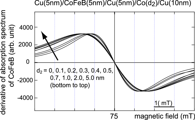
We performed FMR experiments on Cu(5nm)/CoFeB(5nm) /Cu(5nm)/Co()/Cu(10nm) five-layer system shown in Fig. 1 [16], where CoFeB layer corresponds to the F1 layer and Co layer corresponds to the F2 layer. Figure 2 shows the dependence of the derivative of the FMR spectrum of CoFeB on the thickness of Co, . The width of the peak to peak in Fig. 2, namely the linewidth of the FMR spectrum , is a linear function of the Gilbert damping constant [19]:
| (17) |
where is the frequency of the oscillating magnetic field. The line width of CoFeB depends on the thickness of Co through , as shown in Fig. 2. Thus, we can determine the penetration depth of the transverse spin current of Co by the line width of CoFeB. The enhancement of the gyromagnetic ratio does not give any contributions to the line width.
The sample was deposited on Corning 1737 glass substrates using an rf magnetron sputtering system in an ultrahigh vacuum below Pa and cut to 5 nm2. The Ar pressure during deposition was 0.077 Pa. The FMR measurement was carried out using an X-band microwave source ([GHz]) at room temperature. The microwave power, modulation frequency, and modulation field are 1 mW, 10 kHz, and 0.1 mT, respectively. The precession angle of the magnetization of the F1 layer was estimated to be 1 deg. The resistivity of CoFeB and Co are 1252 nm and 210 nm [20], respectively. The magnetization () and the gyromagnetic ratio of CoFeB are 1.66 T and 1.846 Hz/T, respectively.
A Cu layer typically shows an enhanced (111) orientation and the Co layer on it also shows an induced (111) texture. Thus, the Co layer is considered to be (111) texture.

In Fig. 3 the measured line width of the FMR, , of CoFeB layer is plotted with full circles against the thickness of Co layer, . The solid line is a fit to the experimental data according to the theory with the finite penetration depth of the transverse spin current . The dotted line is the calculated line width assuming . If the Co film is not continuous but consists of a Co islands, the thickness of the Co island is somewhat thicker than the nominal thickness. However, the effect of the Co islands is not so significant because the important quantity in our analysis is the mean thickness which is almost same as the nominal thickness.
The best fitting parameters are as follows. The real part of the mixing conductances per unit area, , of CoFeB and Co are 128 nm-2 and 20 nm-2, respectively. Although these values are determined by fitting, they have good agreement with the ab initio calculations [8]. For simplicity, we assume that , where the values of of CoFeB and Co are 0.8 nm-2 and 6.0 nm-2,respectively. The spin diffusion length of CoFeB and Co layer are 12 nm and 38 nm, respectively [20],[21]. The polarization of the conductance are 0.56 for CoFeB and 0.31 for Co [20],[21]. We take nm-2 and nm-2 both CoFeB and Co [15]; these are not important parameters for fitting. The spin diffusion length and resistivity of Cu are taken to be 500 nm and 21 nm [22].
The obtained value of the penetration depth of Co is nm. References [9],[10],[11] estimate , and predict that of Co with (111) texture is 1.1 nm. Thus, we have good agreement with [9],[10],[11].
IV Conclusion
In conclusion, we study the line width of the FMR spectrum of Cu/CoFeB/Cu/Co/Cu five-layer system. The line width of the CoFeB layer depends on the thickness of the Co layer due to spin pumping. We extend the conventional theory of spin pumping by taking into account the finite penetration depth of the transverse spin current of the Co layer, and analize the experimental data. The obtained penetration depth of the Co layer is 1.7 nm, which has good agreement with the Boltzmann theory of electron transport.
Acknowledgment
This work was supported by NEDO. One of the authors (T.T.) is supported by Research Fellowship of Japan Society for the Promotion of Science for Young Scientist.
References
- [1] J. C. Slonczewski, ”Current-driven excitation of magnetic multilayers,” J. Magn. Magn. Mater., vol.159, pp.L1-L7, 1996.
- [2] L. Berge, ”Emission of spin waves by a magnetic multilayer traversed by a current,” Phys. Rev. B, vol.54, pp.9353-9358, 1996.
- [3] S. I. Kiselev et al., ”Microwave oscillations of a nanomagnet driven by a spin-polarized current,” Nature, vol.425, pp.380-383, 2003.
- [4] A. Deac et al., ”Spin transfer effects in exchange-biased spin-valves for current-perpendicular-to-plane magnetoresistive heads,” J. Magn. Magn. Mater., vol.290-291, pp.42-47, 2005.
- [5] J. Z. Sun, ”Spin-current interaction with a monodomain magnetic body: a model study,” Phys. Rev. B, vol.62, pp.570-578, 2000.
- [6] J. Grollier et al., ”Field dependence of magnetization reversal by spin transfer,” Phys. Rev. B, vol.67, pp.174402, 2003.
- [7] M. D. Stiles and A. Zhangwill, ”Anatomy of spin-transfer torque,” Phys. Rev. B, vol.66, pp.014407, 2002.
- [8] A. Brataas, G. E. W. Bauer and P. J. Kelly, ”Non-collinear magnetoelectronics,” Phys. Rep., vol.427, pp.157-255, 2006.
- [9] S. Zhang, P. M. Levy and A. Fert, ”Mechanisms of spin-polarized current-driven magnetization switching,” Phys. Rev. Lett., vol.88, pp.236601, 2002.
- [10] A. Shpiro, P. M. Levy and S. Zhang, ”Self-consistent treatment of nonequilibrium spin torques in magnetic multilayers,” Phys. Rev. Lett., vol.88, pp.236601, 2002.
- [11] J. Zhang, P. M. Levy, S. Zhang and V. Antropov, ”Identification of transverse spin currents in noncollinear magnetic structures,” Phys. Rev. Lett., vol.93, pp.256602, 2004.
- [12] S. Urazhdin, R. Loloee and W. P. Pratt. Jr., ”Noncollinear spin transport in magnetic multilayers,” Phys. Rev. B, vol.71, pp.100401(R), 2005.
- [13] W. Chen, M. J. Rooks, N. Ruiz, J. Z. Sun and A. D. Kent, ”Spin transfer in bilayer magnetic nanopillars at high fields as a function of free-layer thickness,” Phys. Rev. B, vol.74, pp.144408, 2006.
- [14] T. Taniguchi, S. Yakata, H. Imamura and Y. Ando, ”Determination of penetration depth of transverse spin current in ferromagnetic metals by spin pumping,” Appl. Phys. Express, vol.1 pp.031302, 2008.
- [15] Y. Tserkovnyak, A. Brataas, G. E. W. Bauer and B. I. Halperin, ”Nonlocal magnetization dynamics in ferromagnetic heterostructures,” Rev. Mod. Phys., vol.77, pp.1375-1421, 2005.
- [16] S. Mizukami, Y. Ando and T. Miyazaki, ”Effect of spin diffusion on Gilbert damping for a very thin permalloy layer in Cu/permalloy/Cu/Pt films,” Phys. Rev. B, vol.66, pp.104413, 2002.
- [17] T. Valet and A. Fert, ”Theory of the perpendicular magnetoresistance in magnetic multilayers,” Phys. Rev. B, vol.48, pp.7099-7113, 1993.
- [18] T. Taniguchi and H. Imamura, ”Enhancement of the Gilbert damping constant due to spin pumping in noncollinear ferromagnet/nonmagnet/ferromagnet trilayer systems,” Phys. Rev. B, vol.76, pp.092402, 2007.
- [19] S. V. Vonsovskii, Ferromagnetic Resonance, (Israel Program for Scientific Translations Ltd., Jersalem, 1964.) Chap.II, pp.66-70
- [20] L. Piraux, S. Dubois, A. Fert and L. Belliard, ”The temperature dependence of the perpendicular giant magnetoresistance in Co/Cu multilayered system,” Eur. Phys. J. B, vol.4, pp.413-420, 1998.
- [21] H. Oshima et al., ”Perpendicular giant magnetoresistance of CoFeB/Cu single and dual spin-valve films,” J. Appl. Phys., vol.91, pp.8105-8107, 2002.
- [22] J. Bass and W. P. Pratt. Jr., ”Spin-diffusion length in metals and alloys, and spin-flipping at metal/metal interfaces: an experimentalist’s review,” J. Phys.: Condens. Matter, vol.19, pp.183201, 2007.