Non-magnetic simplified cylindrical cloak with suppressed order scattering
Abstract
A type of simplified cloaks with matched exterior boundaries is proposed. The cloak uses non-magnetic material for the TM polarization and can function with a relatively thin thickness. It is shown that the order scattering of such cloak is dominant among all cylindrical scattering terms. A gap is added at the cloak’s inner surface to eliminate the order scattering, through the mechanism of scattering resonance. The reduction in scattering is relatively smooth, indicating that the proposed scattering reduction method has good tolerance to perturbations. Numerical simulations also confirm that the proposed structure has very low scattering.
PACS numbers: 41.20.Jb, 42.25.Fx
Recently, invisibility cloaks have attracted intense attentions due to their amazing optical properties P ; L1 ; S ; C1 ; Cm ; R ; C ; L2 ; YM1 ; YM2 ; C2 . An ideal invisibility cloak can exclude light from a protected region without perturbing the exterior fields. The parameters of invisibility cloaks can be easily obtained from coordinate transformation method P . According to the number of transformed coordinates, invisibility cloaks can be classified into two-dimensional ones (line-transformed cloak) or three-dimensional ones (point-transformed cloak) Yan2 . Most of publications on invisibility cloaks are focused on two-dimensional cloaks, especially cylindrical cloaks S ; C1 ; Cm ; R ; YM1 ; YM2 ; C2 .
As described in Ref. [1], a two-dimensional cylindrical cloak can be easily constructed by compressing a cylindrical region into a concentric cylindrical shell radially. The coordinate transformation is described by the function with and . Under free space background, the relative permittivity and permeability of cloak are as following , and , where . Choosing various , we can obtain cloaks with different parameters. However, and are always infinitely large at the inner boundary regardless of owing to . Thus, in order to avoid this unphysical singularity and make the implementation practical, we should simplify the parameters of cloak. The simplification principle is to keep and () the same as the ideal case S ; Cm .
In Ref. [3], the simplified linear cloak with , and , is proposed and experimentally demonstrated for the TE polarization. However, as pointed in Ref. [9], this simplified cloak leads to considerable scattering for both order and high order cylindrical waves. A major factor for the high scatterings is due to mismatched exterior boundary. In Refs. [10] and [11], the authors proposed two different types of simplified cloaks with matched exterior boundary. The high order scatterings for such cloaks are reduced substantially, due to matched exterior boundary. Hence, the cloaking performance is improved significantly. However, as pointed in Ref. [10], the order scattering is still considerable. It indicates that the cloak operates similarly as a small-sized cylindrical rod, for which the scatterings are mainly contributed from the order scattering. As shown in Ref. [12], the order scattering for the small size rod can be eliminated by employing an appropriate layer outside the rod. This idea can also be utilized to the cloak structure. In this paper, we will analyze how to eliminate the order scattering of simplified cloaks by employing an appropriate layer.
It is worth noting that the simplified cloaks proposed in Ref. [10] have drawbacks of requiring magnetic materials even for a single polarization, while the cloaked proposed in Ref [11] having the size restriction of . In order to overcome these drawbacks, here we propose another transformation function
| (1) |
The parameters of a cloak obtained from such a transformation are:
| (2) |
It is seen from Eq. (2) that the parameters of the cloak at the exterior boundary is the same as free space, i.e., the exterior boundary matches perfectly with free space. Since , the cloak can be made non-magnetic for the TM polarization. In particular, different from Ref. [11], the cloak proposed in the present paper does not have any size restrictions, since is always a monotonic increasing function at . The monotonic increasing property is clearly seen from , which is always positive at .
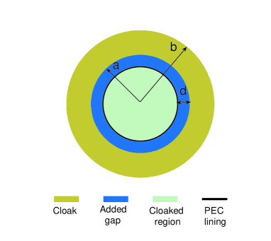
In the following, our discussions will be focused on the cloak with parameters expressed in Eq. (2). Only the TM polarization will be considered, since the cloak can be made non-magnetic under this polarization. In order to make the performance of the cloak independent of the material inside the cloaked region, a PEC lining is put at the boundary of the cloaked region [10]. To maintain the matched exterior boundary, the embedded layer to eliminate the order scattering is put at the inner boundary of the cloak. Consider the simplest case that the embedded layer is just free space, i.e., a gap is imposed at the cloak’s inner surface. In the following, we will focus on this case with the structure illustrated in Fig. 1, where it is seen that a gap with a width is added between the cloak and the cloaked region.
To choose the appropriate thickness of the imposed gap, the order scattering coefficient of the proposed structure needs to be analyzed. Since varies only with , an asymptotic approach can be employed to calculate the order scattering coefficient. We firstly divide the cloak into gradient layers. Then, we are able to calculate the scattering coefficient or , analytically using a matrix method. is characterized by
| (3) |
with
| (4) |
| (5) |
where and (); with ().
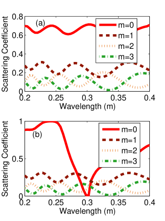
From Eq. (3), as a function of can be easily obtained. Finally, the value of for eliminating the order scattering can be approached by solving . For an example when , , and the wavelength is , the value for is calculated to be .
To illustrate the effect of the added gap, we carry out simulations for this example with commercial COMSOL Mutiphysics package. For comparison, the case without the gap is also simulated. The scattering coefficients versus wavelength for these two cases are plotted in Fig. 2. It is seen that the order scattering reduces dramatically around by employing the gap, which agrees well with above analysis. This cancellation phenomenon is due to the scattering resonance. It is also seen from Fig. 2(b) that the order scattering approaches zero quite smoothly. Within certain wavelength range near , the order scattering is relatively small. This in turn means that the order scattering at should be very small even when the thickness of the gap deviate from ideal design values. Thus, this effect is relatively insensitive to perturbations of the structure. Besides the dip in the scattering, there exists a peak around , which is also due to the anti scattering resonance. For high order scattering terms, no obvious difference between two cases is observed. It is due to the fact that the fields are almost zero near the inner boundary of cloak for high order terms [9].
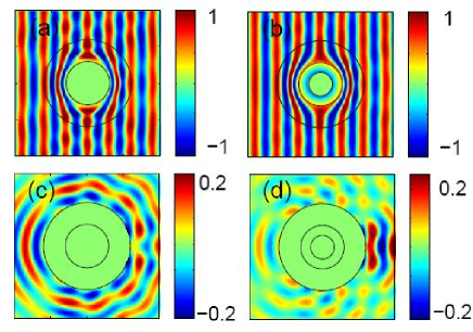
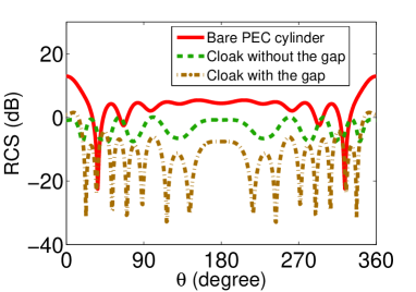
In Fig. 3(a) and 3(b), snapshots of fields at for the case without the gap and the case with the gap are plotted, respectively. It is clearly seen that the performance of the cloak is improved by imposing the gap. The difference can be further confirmed in Fig. 3(c) and 3(d), where only the scattering fields for two cases are plotted. Considerable reduction in scattering is observed. In Fig. (4), the radar cross section (RCS) normalized by the wavelength is plotted for the bare PEC cylinder, the cloak without the gap, and the cloak with the gap, respectively. It is seen that the RCS is reduced dramatically by imposing such a gap. The RCS of backscattering, i.e., at , is about and for the bare PEC cylinder and the cloak without the gap; while the RCS of the backscattering is only for the cloak with the gap. RCS also oscillates with angles much faster, which indicates the order scattering is eliminated and the high order scatterings dominate.
In conclusion, we proposed a type of simplified cloaks, which is non-magnetic for the TM polarization and has no any restrictions on cloak thickness. Since the designed simplified cloaks suffer from a high order scattering, we then proposed a method to eliminate the order scattering. This is achieved by imposing a gap between the cloak and the cloaked region. Due to the destructive scattering resonance, we can achieve complete cancellation of the order scattering for certain thickness at the desired wavelength. The overall scattering of the cloak is thus significantly reduced.
References
References
- (1) J. B. Pendry, D. Schurig, and D. R. Smith, Science 312, 1780 (2006).
- (2) U. Leonhardt, Science 312, 1777 (2006).
- (3) D. Schurig, J. J. Mock, B. J. Justice, S. A. Cummer, J. B. Pendry, A. F. Starr, and D. R. Smith, Science 314, 977 (2006).
- (4) W. Cai, U. K. Chettiar, A. V. Kildishev, V. M. Shalaev, Nat. Photonics 1, 224-227(2007).
- (5) S. A. Cummer, B. I. Popa, D. Schurig, D. R. Smith, and J. B. Pendry, Phys. Rev. E. 74, 036621 (2006).
- (6) Z. C. Ruan, M. Yan, C. W. Neff, and M. Qiu, Phys. Rev. Lett. 99, 113903 (2007).
- (7) H. S. Chen, B. I. Wu, B. L. Zhang, and J. A. Kong, Phys. Rev. Lett. 99, 063903(2007).
- (8) U. Leonhardt, New J. Phys. 8, 247 (2006).
- (9) M. Yan, Z. C. Ruan, and M. Qiu, Phy Rev. Lett. 99, 233901(2007)
- (10) M. Yan, Z. C. Ruan, and M. Qiu, Opt. Express 15, 17772(2007).
- (11) W. Cai, U. K. Chettiar, A. V. Kildishev, V. M. Shalaev, and G. W. Milton, Appl. Phys. Lett. 91, 111, 105(2007).
- (12) W. Yan, Min. Yan, and M. Qiu, New J. Phys. 10, 043040(2008).
- (13) A. Alu and N. Engheta, Phys. Rev. E. 72, 016623(2005).
Figure captions
Figure 1: (Color online) Schematic picture of the proposed cloak structure. A gap of free space with width is imposed between the cloak and the PEC lining.
Figure 2: (Color online) Scattering coefficients of cylindrical versus wavelength for the case (a) without the gap and the case (b) with the gap. The structure parameters are , .
Figure 3: (Color online) Snapshots of fields at for the case (a) without the gap, and the case (b) with the gap; The scattered fields at for the case (c) without the gap, and the case (d) with the gap. The structure parameters are the same as in Fig. 2.
Figure 4: (Color online) RCS normalized by wavelength for the bare PEC cylinder, the cloak without the gap, and the cloak with the gap. The structure parameters are the same as in Fig. 2, and .