GRADUATE COURSE IN PHYSICS
University of Pisa
The School of Graduate Studies in Basic Sciences ”GALILEO
GALILEI”
Researches on Non-standard Optics for Advanced Gravitational Waves Interferometers.
PhD thesis ( cycle )
Supervisor:
Dr. R. DeSalvo
Internal Supervisor:
Prof. F. Fidecaro
2007
LIGO-P080010-00-R
“I’ ve seen things you people wouldn’ t believe. Attack ships on fire off the shoulder of Orion. I watched C-beams … glitter in the dark near Tannhauser Gate. All those … moments will be lost … in time, like tears … in rain. Time … to die.”
Roy Batty, Blade Runner, 1982.
Acknowledgements.
First of all, I would like to thank my advisor, Riccardo DeSalvo, for his support, encouragement and for giving me so much freedom to explore and discover new areas of physics. I must say I am very pleased with the opportunity of being his student; for the challenging and rich experience and intellectual growth it represented, and for the energy he transmitted to me when moving throughout such a long way. Many thanks to my co-workers, from whom I received invaluable guidance and knowledge: Marco Giacinto Tarallo, Erika D’Ambrosio, Phil Willems, John Miller, Virginio Sannibale, Innocenzo Pinto and Vincenzo Galdi. In particular, I single out one of them, who have been not only a collaborator but also genuine friend. With Marco I enjoyed discussing research topics but also Borbonian, WWE and QUEFEF problems and had the best racquetball matches ever. During my stay in Pasadena I had the opportunity of sharing my way with people from the almost all over the world (even if most of them from Italy) and this was a real treasure. My housemates, Kalin, Snejana, Ganesh, Detchev family, my friends Artan, Alberto, Ciro e Simona, Misha e Cinzia, Monica, Paola, Enrico, and all the other “Caltech little Italy” friends; each of them in their own particular and unforgettable way made these years more than a nice memory. Thanks to family and friends for their presence and positive spirit that helped me to further my PhD adventure. I express my deepest gratitude and all my love to Chiara, who has been bringing so much more into my life than I could ever dream. I thank her for the patience, trust and support she has given during these hard times, while I have been working over a thousand miles away. The author gratefully acknowledge the support of the United States National Science Foundation for the construction and operation of the LIGO Laboratory and the Science and Technology Facilities Council of the United Kingdom, the Max-Planck-Society, and the State of Niedersachsen/Germany for support of the construction and operation of the GEO600 detector. The author also gratefully acknowledge the support of the research by these agencies and by the Australian Research Council, the Council of Scientific and Industrial Research of India, the Istituto Nazionale di Fisica Nucleare of Italy, the Spanish Ministerio de Educacion y Ciencia, the Conselleria d’Economia Hisenda i Innovacio of the Govern de les Illes Balears, the Scottish Funding Council, the Scottish Universities Physics Alliance, The National Aeronautics and Space Administration, the Carnegie Trust, the Leverhulme Trust, the David and Lucile Packard Foundation, the Research Corporation, and the Alfred P. Sloan Foundation.Chapter 1 Introduction
Gravitational waves111In this thesis we decided to present only the subjects which are strictly related to the research topics of our work. The reader is addressed to references Carroll ; Gravitation ; ph237 for an introduction to the subject or an in-depth treatment of gravitational waves physics., one of the more discussed predictions of Einstein’s General Theory of Relativity may be detected within the next few years. General Relativity predicts that massive accelerating and rotating astrophysical objects emit gravitational waves which propagate through space with the speed of light. Gravitational waves are most simply thought of as ripples in the space-time fabric, their effect being to change the separation of adjacent masses on earth or in space; this tidal effect is the basis of all present detectors. Sources such as interacting black holes, coalescing compact binary systems, supernova explosions and pulsars are all possible candidates for detection; observing signals from them will significantly boost our understanding of the Universe.
The first gravitational wave detectors were based on the effect of these tidal forces on the fundamental resonant mode of aluminum bars at room temperature. Initial instruments were constructed by Joseph Weber Weber . Following the lack of confirmed detection of signals, aluminum bar systems operated at and below the temperature of liquid helium were developed and work in this area is still underway Allegro ; Auriga ; Exp-Naut . However the most promising design of gravitational wave detectors, offering the possibility of very high sensitivities over a wide range of frequency, uses widely separated test masses freely suspended as pendulums on earth Saulson or in a drag free craft in space; laser interferometry provides a means of sensing the motion of the masses produced as they interact with a gravitational wave. Ground based detectors of this type have the sensitivity to observe sources whose radiation is emitted at frequencies above a few Hz, and space borne detectors will be developed for implementation at lower frequencies. Already gravitational wave detectors of long baseline are operating in a number of places around the world; in the USA (LIGO project LIGO led by a Caltech/ MIT consortium) , in Italy (VIRGO project Virgo , a joint Italian/French venture), in Germany (GEO project Geo , a UK/German collaboration) and in Japan (TAMA 300 project Tama ) . LISA LISA , a space-based detector proposed by a collaboration of European and US research groups, is one of the most challenging large scale experiment of the next future. This detector array should have the capability of detecting gravitational wave signals from many astrophysical events in the Universe, providing unique information on testing aspects of General Relativity and opening up a new field of astronomy.
Gravitational wave strengths are characterized by the gravitational wave amplitude , given by , where is the change in separation of two masses a distance apart. Unlike electromagnetism, gravitational radiation field is quadrupole in nature and this shows up in the pattern of the interaction of the waves with matter. The problem for the experimental physicist is that the predicted magnitudes of the amplitudes or strains in space in the vicinity of the earth caused by gravitational waves even from the most violent astrophysical events are extremely small, of the order of or lower (for a review of the gravitational wave sources and expected signal strength see Cut-Thorne ). Indeed current theoretical models on the event rate and strength of such events suggest that in order to detect a few events per year, from coalescing neutron star binary systems for example, an amplitude sensitivity close to over timescales as short as a millisecond is required. If the Fourier transform of a likely signal is considered, it is found that the energy of the signal is distributed over a frequency range or bandwidth which is approximately equal to timescale. Thus detector noise levels must have an amplitude spectral density lower than over the frequency range of the signal. The weakness of the signal means that limiting noise sources like the thermal motion of molecules in the detector (thermal noise), seismic or other mechanical disturbances, and noise associated with the detector readout, whether electronic or optical, must be reduced to a very low level. For signals above ground based experiments are possible, but for lower frequencies where local fluctuating gravitational gradients and seismic noise on earth become a problem, it is best to consider developing detectors for operation underground AspenRic or in space LISA .
Gravitational wave detector using laser interferometry, offers the possibility of very high sensitivities over a wide range of frequency. It uses test masses which are widely separated and freely suspended as pendulums to isolate against seismic noise; laser interferometry provides a means of sensing the motion of these masses produced as they interact with a gravitational wave.
This technique is based on the Michelson interferometer and is particularly suited to the detection of gravitational waves as they have a quadrupole nature. Waves propagating perpendicular to the plane of the interferometer will result in one arm of the interferometer being increased in length while the other arm is decreased and vice versa. The induced change in the length of the interferometer arms results in a small change in the intensity of the light observed at the interferometer output. The sensitivity of an interferometric gravitational wave detector is limited by noise from various sources. Taking this frequency dependent noise floor into account, the American LIGO detectors have a sensitivity (shown in Fig. 1.1), which would allow a reasonable probability for detecting gravitational wave sources.
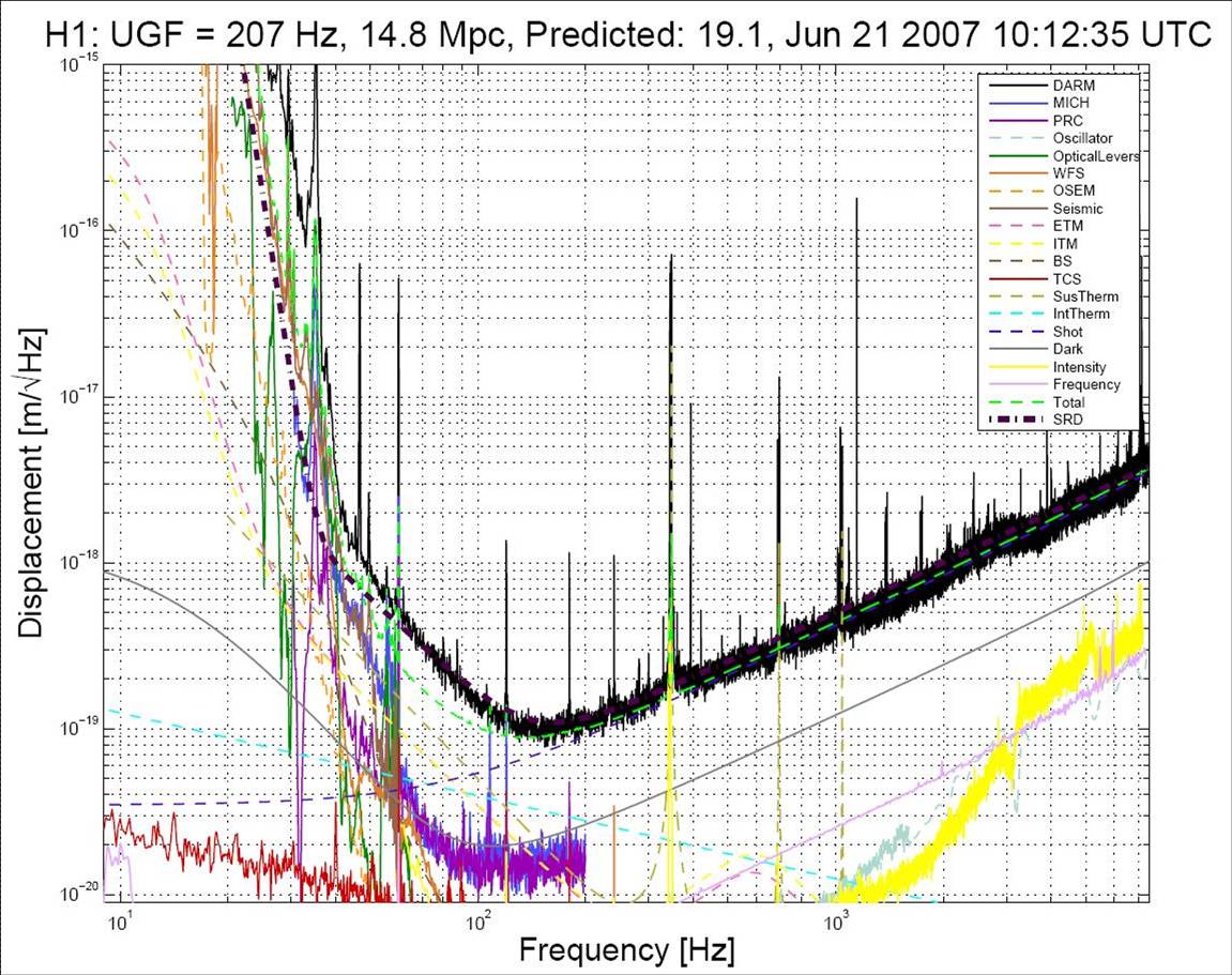
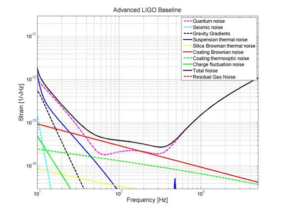
In order to observe a full range of sources and to initiate gravitational wave astronomy, a sensitivity or noise performance approximately ten times better in the mid-frequency range and several orders of magnitude better at Hz, is desired. Such a performance is planned for a future LIGO upgrade, Advanced LIGO AdLIGO .
In general, for ground based detectors the most important limitations to sensitivity result from the effects of seismic and other ground-borne mechanical noise, thermal noise associated with the test masses and their suspensions and shot noise in the photocurrent from the photodiode which detects the interference pattern.
Most modern designs implement improved versions of a simple Michelson interferometer (see Fig. 1.2). A simple Michelson interferometer has an antenna response function which has a maximum sensitivity for ,where is the round-trip travel time for photons leaving and returning to the beamsplitter and is the period of the gravitational wave signal ( the length of each arm). A simple calculation from this expression shows that for frequency between and , the optimal antenna length is of order to . This is much larger than would be feasible for an earth based detector.
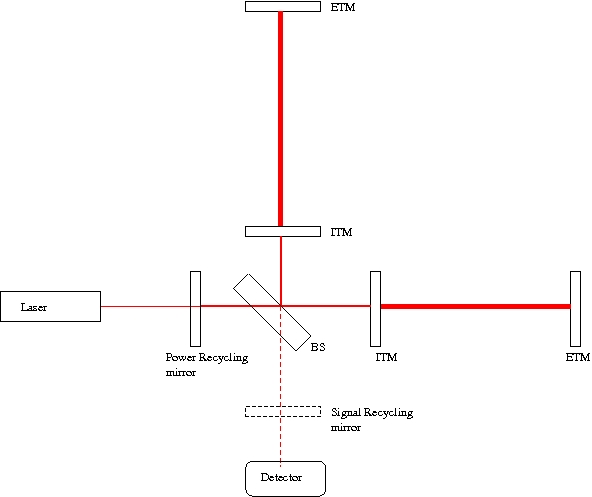
The situation can be helped greatly if a multi-pass arrangement is used in the arms of the interferometer as this multiplies up the apparent movement by the number of bounces the light makes in the arms. The multiple beams can either be separate as in an optical delay line, like the GEO configuration, or may lie on top of each other as in a Fabry-Perot resonant cavity, used in all others interferometric gravitational waves detectors. A Fabry-Perot cavity consists of a partially transmitting input mirror and a high reflective rear mirror. If the length of the Fabry-Perot is adjusted to a multiple of the laser wavelength the cavity becomes resonant. The light power inside the cavity builds up and simulates the effect of sending the light forth and back multiple times. However, in this case the number of bounces is not a fixed quantity, but rather an averaged effective value. Optimally, the light should be stored for a time comparable to the characteristic timescale of the signal. Thus if signals of characteristic timescale are to be searched for, the number of bounces should be approximately for an arm length of .
If the mirrors have low optical losses and if the rear mirror is a high reflector, most of the power incident to a Fabry-Perot arm cavity will be reflected back to the beam splitter. Ideally, the anti-symmetric port of the Michelson interferometer is set on a dark fringe to minimize shot noise Edelstein . Then a differential length change induced by a gravitational wave will leave through the anti-symmetric port with the highest possible signal-to-noise ratio. This in turn means that most of the injected light will leave the interferometer through the symmetric port and be lost. By placing an additional partially transmitting mirror at input one can form yet another cavity, the power recycling cavity, and recycle most of the otherwise lost light. The interferometer response is then enhanced by the power recycling gain (the shot noise is reduced by the additional power build-up in the power recycling cavity) and this configuration is called Power-recycled Michelson with Fabry-Perot arm cavities. By adding a partially transmitting mirror to the anti-symmetric output port the gravitational wave signal can be made resonant Strain . This makes it possible to shape the interferometer response, so that its sensitivity is improved in a narrow frequency band around the signal resonance. In general, this means that the sensitivity outside the resonant frequency band will be worse. This is not a problem at lower frequencies where the interferometer is usually limited by seismic noise. If both power and signal recycling are implemented the configuration is called dual recycled.
1.1 Topics discussed in this thesis
Thermal noise of the test masses is expected to be a limiting factor in Advanced GW interferometers. As an example, Fig. 1.3 shows the expected sensitivity curve for Advanced LIGO interferometer with the main noise contribution enlightened. Many research groups work on activities finalized to improve the thermal noise performance of next generation detectors. Some research lines deal with cryogenic temperature, other with improved or new materials, other with optical beam shaping and optimization of the mirror geometry and/or coating. Non Gaussian beams have been proposed years ago reducing ; erika to reduce a particular type of thermal noise (substrate thermoelastic).
In this thesis we provide a quantitative analysis of the impact of non-Gaussian beams on different kinds of thermal noises222In particular we show that the thermal noise of the mirror’s dielectric coating is greatly reduced by using flat profile beams. This resolved a question raised Tourn-Elba on the effectiveness of this type of beam on coating noise. We show that the mesa beam implementation could boost the Advanced LIGO sensitivity considerably: even with a rough estimation (without re-optimizing the detector for the introduction of mesa beams), the binary neutron star inspiral range increases from Mpc to Mpc.
We illustrate the importance of uniform sampling of the mirror surface to reduce thermal noise and the limitation brought by the use of excited modes with nodes on the mirror surface.
We developed the theory of mesa beam, in view of a future implementation in advanced GW interferometers of the mesa beam idea, focusing on the analytical derivation of the quantities (beam width, divergence, factor, etc…), which are chosen as “ISO standard” ISO reference parameters for the characterization of an optical beam.
We also analytically proved a new duality relation between optical cavities with non-spherical mirrors. This derivation provides a unique mapping between the eigenvalues and eigenvectors of two cavities whose mirrors shapes are related by a simple relation. This duality allows the direct application of beam property calculations performed in a case to geometries of the other configuration.
The interest of the GW community in this new beam technology led us to the construction and testing of a prototype mesa beam Fabry-Perot cavity with mexican-hat mirror. Part of the work of this thesis was devoted to the development of new simulation programs of optical systems333Available at http://www.ligo.caltech.edu/~jagresti/. These programs provided the theoretical expected behavior of our experiment, in particular cavity’s modes structure and misalignments sensitivity to be confronted with the experimental results. We developed new simulation packages to analyze the performance of our cavity prototype with real imperfect mirrors, using the measured mirrors maps. The model developed can include uniform and non-uniform scattering and absorption losses, as well as the effects of mirror heating A particular attention has been devoted to keep theses simulation programs very easy to use and very easy to change/upgade444 Most of the time we used Mathematica® for its capability of analytical manipulation and numerical analysis or Matlab® for its ability in manipulating large matrices. by anyone involved in optics research555The great simplicity and versatility of these programs turned to be fundamental properties for the usage by other research groups.. The good agreement between theory and experiment validated the mathematical tools here developed thus allowing safe extrapolation to the larger optical systems needed in GW observatories.
We also explored another complementary way of reducing the mirror thermal noise, beside the beam shaping, that is the multi-layered coating thickness optimization. We show it to be effective in reducing the coating noise and explore the possible implications for GW interferometers in terms of sensitivity.
During this analysis we developed an independent model for the coating effective elastic parameters, which is based on the well understood subject of homogenization theory.
Chapter 2 Paraxial beam and optical cavities
2.1 Introduction
This chapter is a brief description of the techniques used in this thesis to study paraxial laser beam propagation and optical resonators. It gives an overview of the main concepts related to standard spherical mirrors optics, and some less known concepts related to generic paraxial beam and resonators which is one of the main subject of this work. The reader familiar with these techniques can jump to Chapter 3.
2.2 Paraxial laser beams
Radiation from lasers is different from conventional optical light because it is very close to be monochromatic. Although each laser has its own fine spectral distribution and noise properties, the electric and magnetic fields from lasers are considered to have minimal phase and amplitude variations in the first-order approximation. Like microwaves from a maser, electromagnetic radiation with a precise phase and amplitude is described most accurately by Maxwell’s wave equations. For devices with structures that have dimensions very much larger than the wavelength, e.g. in a multimode fiber or in an optical system consisting of lenses, prisms or mirrors, the rigorous analysis of Maxwell’s vector wave equations becomes very complex and tedious: there are too many modes in such a large space. It is difficult to solve Maxwell’s vector wave equations for such cases, even with large computers. Even if we find the solution, it would contain fine features (such as the fringe fields near the lens) which are often of little or no significance to practical applications. In these cases we look for a simple analysis which can give us just the main features (i.e. the amplitude and phase) of the dominant component of the electromagnetic field in directions close to the direction of propagation and at distances reasonably far away from the aperture. When one deals with laser radiation fields which have slow transverse variations and which interact with devices that have overall dimensions much larger than the optical wavelength , the fields can often be approximated as transverse electric and magnetic (TEM) waves. In TEM waves both the dominant electric field and the dominant magnetic field polarization lie approximately in the plane perpendicular to the direction of propagation. For such waves, we usually need only to solve the scalar wave equations to obtain the amplitude and the phase of the dominant electric field along its local polarization direction. The dominant magnetic field can be calculated directly from the dominant electric field. Under these assumption, the Maxwell equations for the beam propagation in free space (or homogeneous and isotropic medium), can be replaced by the scalar wave equation (Helmholtz equation)
| (2.1) |
where is the phasor amplitude of a field component that is sinusoidal in time, is the Laplacian operator and is the laser wavenumber. Then, since laser beams are usually sufficiently collimated, we can describe their diffraction properties using the paraxial wave approximation. If the field is expected to propagate mainly in the direction, with a slow variation of amplitude and phase along the transverse direction, it is convenient to write the field in the following way
| (2.2) |
where is the complex scalar wave amplitude, called envelope function, which describes the transverse profile of the beam. Inserting this into the (Helmholtz) equation (2.1) we find the reduced equation
| (2.3) |
If the dependence of the envelope function is slow compared to the optical wavelength and to the transverse variations of the field, we can drop the second order partial derivative in in (2.3) and obtain the paraxial wave equation
| (2.4) |
This equation can be written for a generic set of transverse coordinates as
| (2.5) |
where s refers to the specific coordinate system, orthogonal to the direction, and means the Laplacian operator in these coordinates.
2.3 Integral approach
Another equally valid and effective way of analyzing paraxial wave propagation is to employ the Huygens-Fresnel principle in the paraxial approximation. Consider an aperture at a plane illuminated with a light field distribution within the aperture. Then for a point lying somewhere after the aperture, say at with coordinates , the net field is given by adding together spherical waves emitted from each point in the aperture. Each spherical wavelet takes on the strength and phase of the field at the point where it originates. Mathematically, this summation takes the form
| (2.6) | ||||
where is the angle under which the aperture element centered at is seen from the observation point and is the distance between these two points. This equation can be rigorously derived from the Rayleigh-Sommerfeld scalar diffraction theory as shown in goodman and rely on the approximation . The paraxial and the Fresnel approximations to diffraction theory consist in approximating the obliquity factor by unity and, once expanded the distance in a power series in the form
| (2.7) |
replacing the denominator of (2.6) by simply and retaining the quadratic terms in the exponent of the phase shift factor . With these approximations we obtain the paraxial approximation of the Huygens-Fresnel integral (2.6)
| (2.8) |
The integral is extended to the entire plane with the assumption that the input field distribution is a paraxial optical beam which transverse profile going to zero outside the region . The integral (2.8) provides a way to propagate an arbitrary optical wavefront from an input plane to any later plane . In the following we will assume . It is useful to note that this integral has exactly the form of a convolution product in the coordinates between the input field and the paraxial diffraction kernel
| (2.9) |
Using the Fourier transform the integral equation (2.8) can be transformed into a simple algebraic product. Consider a complex function (e.g. an optical wave amplitude) of two real variables, of integrable square modulus. Its two dimensional Fourier transform is defined by
| (2.10) |
and the reciprocal transform by
| (2.11) |
The Fourier transform of the propagator can be easily computed
| (2.12) |
and the propagation equation for the transformed field become
| (2.13) |
This equation can be retrieved starting from the Helmholtz equation in the paraxial approximation. Taking the Fourier transform of the equation (2.4) with respect to we obtain the following equation for the Fourier transformed envelope function
| (2.14) |
the solution of which is of the form
| (2.15) |
in which we recover the propagator (2.12) once we reintroduce the phase factor for the complete field.
2.3.1 Paraxial plane waves decomposition
The scalar wave equation (2.1) gives us a formal method for propagating an optical wave forward in space. The main concept in Fourier optics is that we use a Fourier transform to break up an arbitrary field into plane-wave components. Then we propagate the plane waves components, and the linearity of the propagation equations allows the reconstruction of the propagated field. Let’s see how this works. Recall the scalar plane wave solution to the wave equation:
| (2.16) |
where the wave vector indicates the propagation direction of the wave. Let s let the optical axis lie along the z-axis. Then the wave vector has a direction determined by its angles with respect to the z-axis,
| (2.17) |
where and are the transverse spatial frequencies.
That is, in the plane, the electric field has harmonic spatial dependence in the x- and y-directions:
| (2.18) |
This is the central point of Fourier optics: harmonic phase variation in the (x, y) plane (say, at z = 0) corresponds to a plane wave in a particular direction determined by (2.17). That is, the frequency of the harmonic variation determines the direction of propagation. A general field profile at can thus be written as a superposition of plane waves via the Fourier transform:
| (2.19) |
where the spatial frequency distribution is given by
| (2.20) |
Having transformed into the spatial-frequency domain, we can propagate this spatial-frequency distribution forward to any other plane by multiplying it by the phase shift factor , where
| (2.21) |
However in the paraxial approximation, since , the longitudinal component can be written in the form
| (2.22) |
Thus, the free-space transfer function becomes
| (2.23) |
where the first factor is an overall phase factor corresponding to plane-wave propagation along the optical axis, and the second factor generates the evolution of the spatial profile. Combining Eqs. (2.13) and (2.23) we obtain the expression for the propagation of the spatial-frequency components of the paraxial beam which is equal to Eq. (2.13), obtained by applying Fourier theorems to the Huygens-Fresnel integral.
2.4 Gaussian beam
The Gaussian beam is the simplest model of a directed beam that satisfies the Helmholtz equation in the paraxial approximation (2.4). It also turns out that the outputs of spherical mirror resonators and lasers are often Gaussian beams (approximatively), and therefore the theory of Gaussian beams is widely used in gravitational waves interferometric detectors. In most applications the standard Gaussian beam is expressed as
| (2.24) |
In this expression, we have used polar coordinates with ; is an overall field-amplitude constant; is a constant called the Rayleigh length (or “Rayleigh range”);
| (2.25) |
is the beam waist parameter or minimum beam radius
| (2.26) |
is the beam radius as a function of , and
| (2.27) |
is the radius of curvature of the wave front. The intensity is the square modulus of Eq. (2.24)
| (2.28) |
Clearly, the intensity falls off in the radial direction like a Gaussian function, hence the name Gaussian beam. Also, note that the beam spot size correspond to the distance from the optic axis to the point of attenuation of the beam intensity ( in electric field amplitude).
The beam radius traces out a hyperbolic curve in . Near the focus at , the spot size achieves its minimum value . At large distances from the focus, the hyperbola approaches its asymptotes, given by . The Rayleigh length marks the crossover between these two regimes; thus,
for the regions near and far away from the focus, respectively. From this we see that in the far field, the beam propagates in the form of a cone of half angle , called beam divergence, given by
| (2.29) |
where we have used the small angle approximation for the paraxial Gaussian beam. The region in which a gaussian beam can be considered collimated is roughly around the focal plane . Recall that the longitudinal phase factor has the form
| (2.30) |
The first term in the phase is simply the phase of a plane wave propagating in the same direction and with the same optical frequency as the Gaussian beam. The second term is called the Gouy phase shift and represents a small departure from planarity. The longitudinal phase is dominated by the term, but the Gouy term is important as well. It represents a phase retardation compared to the plane wave. Because of the arctan form, the retardation amounts to a total of in phase over all . Gouy effects are generic to focusing-beam-type solutions to the wave equation. As we will see, the Gouy phase is important in computing the resonant frequencies of optical resonators.
Examining the expression of the radius of curvature of the wavefront (2.27) we can see that at the waist , the wavefront is flat, and that in the far field region the radius increases as , i.e., the gaussian beam becomes essentially like a spherical wave centered at the beam waist. The minimum radius of curvature occurs for the wavefront at a distance from the waist given by , with a radius value . In a cavity, the boundary conditions imposed by the cavity mirrors require that the curvature of the spherical mirrors and the curvature of the wave fronts match. This allows the wave to map back on itself. This is one reason why Gaussian beams can exist in resonators as we will see later.
Despite the complex form of the Gaussian beam, relatively little information is needed to completely specify it. For example, if we know where is located, the value of , and the optical wavelength all the other parameters are uniquely fixed. Alternately, it is sufficient to know and at some distance , or it is sufficient to know and at some distance . It is useful the definition of a complex parameter for the gaussian beam, called -parameter
| (2.31) |
| (2.32) |
The propagation of a gaussian beam in free space can be simply computed using the q-parameters; the propagation law between two planes along the optical axis for is established as
| (2.33) |
This result is a particular case of the propagation low of a gaussian beam through various optical structures modelled with the so-called “ABCD” formalism of geometric optics which we will describe briefly in the next section.
2.5 transformation
Matrix optics has been well established a long time ago. Within the paraxial approach, it provides a modular transformation describing the effect of an optical system as the cascaded operation of its components. Then each simple optical system is given by its matrix representation. Before presenting the results of the application of the matrix optics to the Gaussian beam transformation, we need to analyze the basis of this approach (e.g., see Chapter of Ref. siegman ). In paraxial optics, the light is presented as ray trajectories that are described, at a given meridional plane, by its height and its angle with respect to the optical axis of the system. These two parameters can be arranged as a column vector. The simplest mathematical object relating two vectors (besides a multiplication by a scalar quantity) is a matrix. In this case, the matrix is a matrix that is usually called the matrix because its elements are labelled as and . If the input plane and the output plane are in the same optical medium, then the determinant of the matrix is unity, , and the matrix is called unimodular. In the absence of loss, the matrix elements are real, they are complex otherwise.
The relation can be written as:
| (2.34) |
where the column vector with subindex stands for the input ray, and the subindex stands for the output ray. An interesting result of this previous equation is obtained when a new magnitude is defined as the ratio between height and angle.
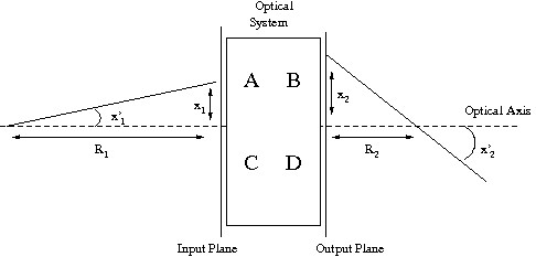
From Fig.2.1, this parameter coincides with the distance between the ray-optical axis intersection and the position of reference for the description of the ray. This distance is interpreted as the radius of curvature of a wavefront departing from that intersection point and arriving to the plane of interest where the column vector is described. When this radius of curvature is obtained by using the matrix relations, the following result is found:
| (2.35) |
This expression is known as the law for the radius of curvature. It relates the input and output radii of curvature of a spherical wavefront passing through an optical system described by its matrix. In recent years, a very useful generalized form of paraxial beam propagation has been developed, in which a generalized Huygens type of integral, describes paraxial wave propagation trough cascade sequences of optical elements, in terms of matrices. Consider an optical system (Fig. 2.1) described by an matrix with real elements and illuminated by a beam with a transverse amplitude distribution at the input plane. The amplitude distribution at the output plane can be written as
| (2.36) |
or for an optical system with cylindrical symmetry
| (2.37) |
If we now consider the transformation of a gaussian beam through a paraxial system described by an matrix, it is possible to prove (ref..) that the complex -parameter introduced in (2.32) transforms according to the simple relation
| (2.38) |
where and are the -parameters before and after the optical system, respectively. The equation (2.38) has the same form of the equation (2.35) for the transformation of the radius of curvature of a spherical wave passing through the optical elements; the q-parameter is also called complex radius of curvature for a gaussian beam. The results of the application of the law can be written in terms of the real radius of curvature and the Gaussian width by properly taking the real and imaginary parts of the resulting complex radius of curvature. When a Gaussian beam propagates along an optical system, its complex radius of curvature changes according to the law. The new parameters of the beam are obtained from the value of the new complex radius of curvature. However, there exists an invariant parameter that remains the same throughout optical systems. This invariant parameter is the product of the minimum beam width with the divergence of the beam
| (2.39) |
Using this relation, we can conclude that a good collimation (very low value of the divergence) will be obtained when the beam is wide. On the contrary, a high focused beam will be obtained by allowing a large divergence angle.
2.6 Higher order modes
In section 2.4, only one solution of (2.5), was discussed, i.e., a light beam with the property that its intensity profile in every beam cross section is given by the same function, namely, a Gaussian. The width of this Gaussian distribution changes as the beam propagates along its axis. There are other solution of (2.5) with similar properties, and they are discussed in this section. These solutions form a complete and orthogonal set of function and are called the modes of propagation. Every arbitrary distribution of monochromatic light can be expanded in terms of these modes. This procedure is largely used in the modal analysis of the light circulating in the gravitational waves interferometers.
Modes in cartesian coordinates
Using cartesian coordinates, a more general solution of the paraxial wave equation is given by the Hermite-Gaussian (HG) beam which can be written as
| (2.40) |
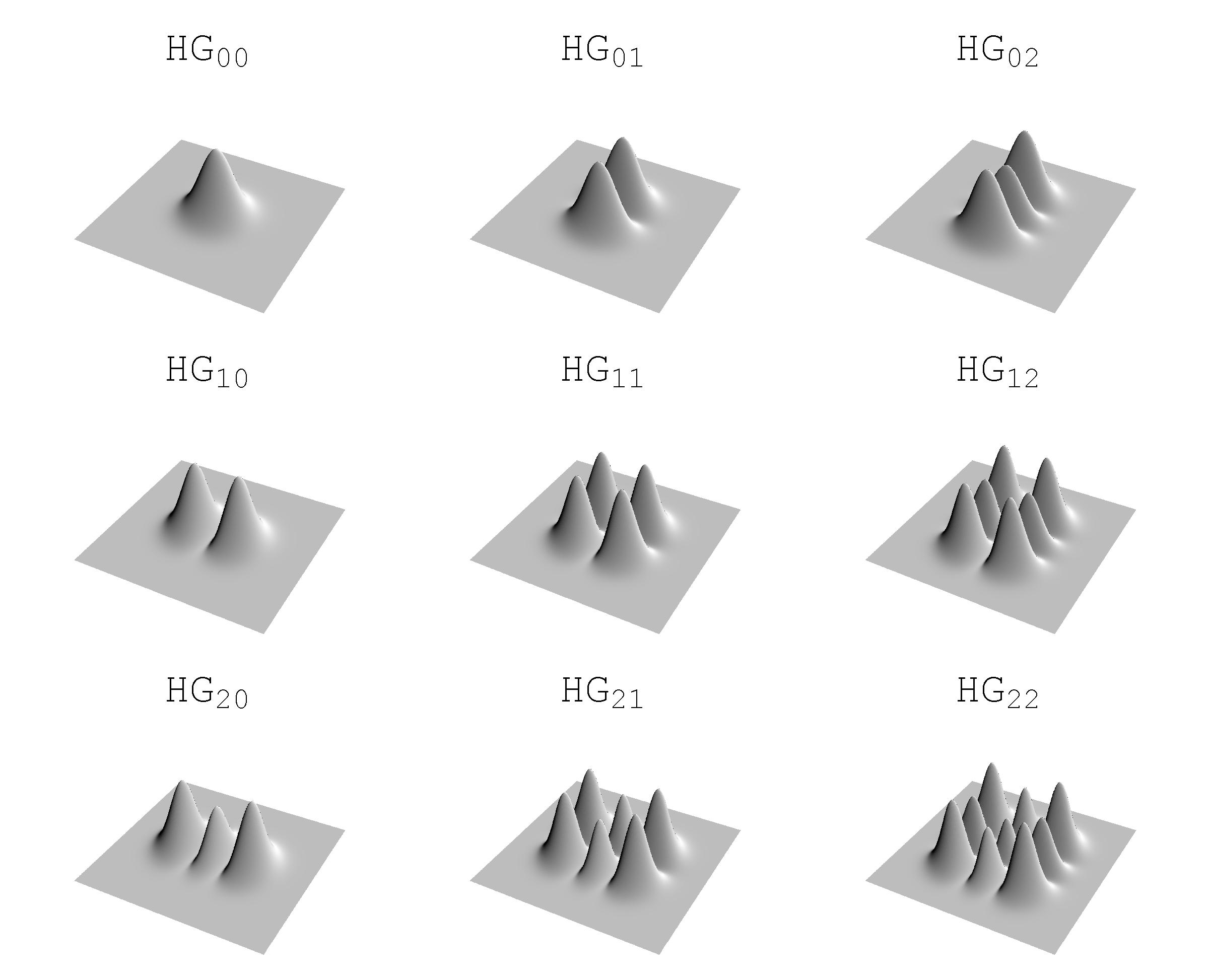
where the functions are the Hermite polynomials of order and the parameters and are the same as for the lowest-order gaussian mode as given in Sec. 2.4. In general, the intensity pattern of the mode, Fig. 2.2, has dark bands across the -direction and dark bands across the -direction, corresponding to the zeros of the Hermite polynomials. Alternately, the intensity pattern has a grid of bright spots in the x-direction and in the y-direction.
Modes in cylindrical coordinates
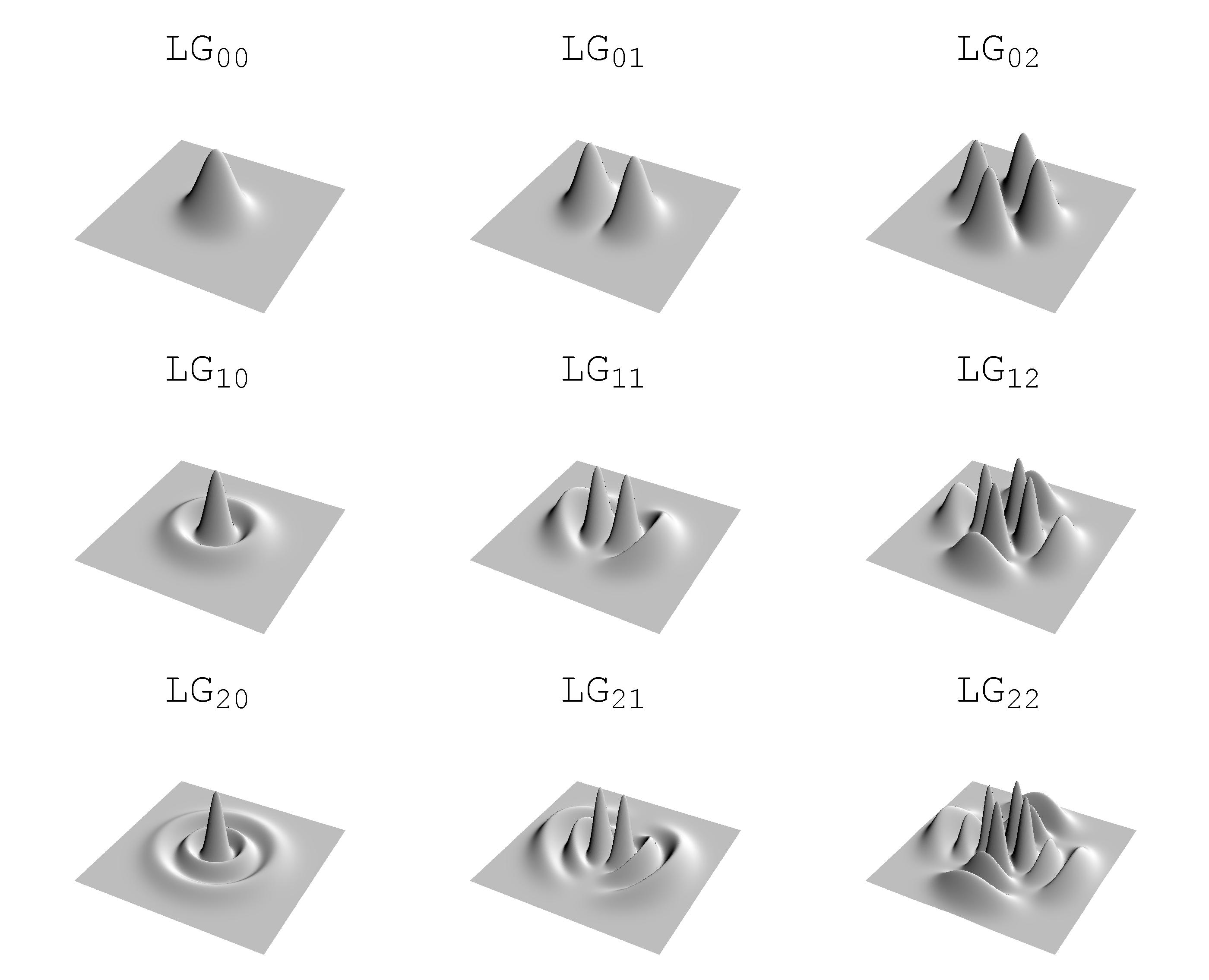
An alternative but equally valid family of solution to the paraxial wave equation (2.5) can be written in cylindrical coordinates and are called Laguerre Gaussian (LG) beams
| (2.41) |
where the integer is the radial index and the integer is the azimuthal mode index (see Fig. 2.3 for the Intensity distribution); the are the generalized Laguerre polynomials and all other quantities are exactly the same as in the Hermite-gaussian case.
2.7 Generic paraxial beam and ABCD transformation
The propagation and transformation of Gaussian, Hermite-Gaussian and Laguerre-Gaussian light beams through paraxial systems are governed by the law (2.38). However, since most of the work in this thesis deals with non-Gaussian (non-HG and non-LG) beams, it is useful to introduce a formalism for the analysis of a non-Gaussian beam by using an extension of the complex beam -parameter. We are going to introduce the most characteristic parameters for a generic paraxial beam, defined in terms of the moments of the intensity distribution and its Fourier transform. These parameters have been introduced in SiegmanR ; BelangerABCD ; PorrasABCD . In the case of orthogonal astigmatic beams, the field is separable in two orthogonal one-dimensional components. If the amplitude distribution in one of these transversal directions is denoted by , then the width of the beam is given by
| (2.42) |
where
| (2.43) |
is the total intensity in the transverse direction and
| (2.44) |
is the mean value of the transversal position of the beam. When is zero, we will say that the beam is on axis. It is easy to check that in the case of a Gaussian distribution, the width is the Gaussian width defined in the previous sections.
As we saw in the definition of the divergence for Gaussian beams, the divergence is related to the spreading of the beam along its propagation. This concept is described analytically by the Fourier transform of the amplitude distribution, i.e., also named as the angular spectrum. In this section the Fourier transform of the amplitude distribution is defined in a slightly different way with respect to (2.10); introducing a factor in the exponent we have
| (2.45) |
where is the transverse spatial frequency that is related to the angle by means of the wavelength. The angular width that is taken as the divergence of the beam is related to the mean-square deviation of the Fourier transform of the amplitude
| (2.46) |
where due to the Parseval’s theorem and
| (2.47) |
is the mean value of the transversal spatial frequency which is related to the angle between the optical axis and the direction of the propagation of the beam by . The mean value of the position, , and the slope of the beam, transform according to the geometrical optics rules (2.34) when the beam passes trough the system.
Another parameter defined in analogy with the Gaussian beam case is the radius of curvature. For totally coherent laser beams, it is also possible to define an effective or generalized radius of curvature for arbitrary amplitude distributions. This radius of curvature is the radius of the spherical wavefront that best fits the actual wavefront of the beam. This fitting is made by weighting the departure from the spherical wavefront with the irradiance distribution. The analytical expression for this radius of curvature can be written as follows:
| (2.48) |
By using the previous definitions, it is possible to introduce a generalized complex radius of curvature as follows:
| (2.49) |
Now the transformation of the complex radius of curvature can be carried out by applying the ABCD law, as it can be proved by using the generalized Huygens integral (2.36) or (2.37), which relates the output beam to the input one and the ABCD elements. It is important to note that there are three parameters involved in the calculation of the generalized complex radius of curvature: and . The application of the ABCD law provides two equations: one for the real part, and one for the imaginary. Therefore we will need another relation involving these three parameters to solve the problem of the transformation of those beams by ABCD optical systems. This third relation is given by the invariant parameter called beam propagation factor111Sometimes it is also called beam quality factor. .
For the Gaussian beam case, we have found a parameter that remains invariant through optical systems. Now in the case of totally coherent non-Gaussian beams, we can define a new parameter that will have the same properties. It will be constant along the propagation through optical systems. Its definition in terms of the previous characterizing parameters is:
| (2.50) |
This invariance, along with the results obtained from the law applied to the generalized complex radius of curvature, allows to calculate the three resulting parameters for an transformation. The value of the parameter has an interesting meaning. It is related to the divergence that would be obtained if the beam having an amplitude distribution is collimated at the plane of interest. The collimation should be considered as having an effective, or generalized, radius of curvature equal to infinity. From the definition of , this is an averaged collimation. The divergence of this collimated beam is the minimum obtainable for such a beam having a generalized width of . The propagation factor can be directly related to the product of the minimum width (waist size) of the beam (defined as variance in the coordinate) times the divergence (defined as variance in the coordinate). The value of for a Gaussian beam is 1, which follows directly by (2.39). It is not possible to find a lower value of the for actual, realizable beams. This property, along with its definition in terms of the variance in and , resembles very well an uncertainty principle. Using these definitions, the transformation of the beam width, divergence and radius of curvature of a generic paraxial beam by a real system from an input plane to an output plane (for simplicity in the following formulas we will assume that the beam is on axis and that the slope is zero at the input plane) can be written as
| (2.51) | ||||
| (2.52) | ||||
| (2.53) |
In particular, if is the plane of the smallest width, the free propagation of the beam and produces these equations
| (2.54) | ||||
| (2.55) |
where we have introduced a generalized Rayleigh distance . Since in the next chapter we will deal with cylindrical symmetric laser beam, it is useful to write the definitions of width, divergence, and radius of curvature in polar coordinates. If the beam is centered and aligned with the optical axis we have
| (2.56) | ||||
| (2.57) | ||||
| (2.58) |
where is the integrated intensity in the transversal plane and is the radial polar coordinate in the spatial frequency plane of the 2D Fourier transform of the field. It can be proved, using the integral transformation (2.37), that the three transformation formulas are identical to the orthogonal case, and therefore the conservation and the ABCD law remain valid for cylindrical symmetric beams. Once we have introduced this moment approach for the propagation of a general paraxial beam, it is useful to characterize the pointing stability, Morin , of a laser beam with a misalignment factor , which provides a global comparison between the misaligned beams and is expressed in the form
| (2.59) |
for the one dimensional case, where is called the misalignment superposition integral, is the field of the perfectly aligned beam and its misaligned copy is described by where and represent the transverse and angular shifts, respectively, of the misaligned beam in a given plane. The level of misalignment can be quantified by the number , which takes a maximum unitary value for a perfectly aligned beam and goes to zero as the misalignment is increased. This number has all the desired features. It takes into account both transverse and angular shifts as well as the width and the divergence of the beam. In essence, this number quantifies by how much the misaligned beam differs in phase and intensity from the perfectly aligned beam in any plane, since it is invariant under propagation through an ideal optical system. For small shifts equation (2.59) reduces to
| (2.60) |
where and are the beam propagation factor, waist width and far-field divergence angle of the beam, in accordance with the second-order moments definition (2.50), (2.42) and (2.46) respectively. In the derivation of (2.60) it was assumed that the transverse shift was measured at the waist plane. The variation range of the misalignment factor is . The larger value of the parameters multiplying the transverse and angular shifts, means that the beam is more sensitive to the misalignment. It is important to stress that the formula (2.60) is a useful criterion to characterize the misalignment sensitivity of different beam geometry and this aspect will be investigated in Sec. 3.4.5.
2.8 Optical cavities with spherical mirrors
An optical cavity 222Optical resonators are often called cavities. This term has been taken over from microwave technology (masers), where resonators really look like closed cavities, while optical resonators normally have a rather “open” kind of setup which doesn’t really look like a cavity. or optical resonator is an arrangement of mirrors that forms a standing wave cavity resonator for light waves. Light confined in a resonator will reflect multiple times from the mirrors, and due to the effects of interference, only certain patterns and frequencies of radiation will be sustained by the resonator, with the others being suppressed by destructive interference. In general, radiation patterns which are reproduced on every round-trip of the light through the resonator are the most stable, and these are known as the modes of the resonator. Cavity modes are self-consistent field distributions of light, more precisely, electric field distributions which are self-reproducing (apart from a possible loss of power) in each round trip. The most common types of optical cavities consist of two facing plane (flat) or spherical mirrors. Now we have seen in Sec. 2.4 that the wavefronts of a Gaussian beam (and its higher order partners HG and LG beams) are paraboloidal surfaces with radii of curvature given by (2.27). Suppose that we fit a pair of curved mirrors to this beam at any two points along the beam in such a way that the radii of curvature of the mirrors are exactly matched to the wavefront radii of the gaussian beam at those two points. If the transverse size of the mirrors is substantially larger than the gaussian spot size of the beam, each of these mirrors will essentially reflect the gaussian beam exactly back on itself, with exactly reversed wavefront curvature and direction. These two mirrors thus form an optical resonator which can support both the lowest-order gaussian mode, and (at slightly different wavelengths) the higher-order HG or LG modes as resonant modes of the cavity. Given two curved mirrors with radii of curvature and , separated by a distance , the calculation of the beam parameters follows directly from imposing that the wavefront curvature must match the mirror curvature at each mirror position. It is useful to introduce the resonator parameters, and , which are a standard notation in the field of optical resonators
| (2.61) |
In terms of these parameters we can find that the self-reproducing gaussian beam has a waist size given by
| (2.62) |
and the spot sizes and at the mirrors surfaces
| (2.63) |
It is obvious from these expressions that real and finite solutions for the gaussian beam spot sizes can exist only if the parameters are confined to a stability range defined by
| (2.64) |
This condition is called stability range because this also exactly describes the condition required for two mirrors with radii and and spacing to form a stable periodic focusing system for optical rays. The stability of an optical cavity can be analyzed from the ray-optics point of view. Light rays that bounce back and forth between the spherical mirrors of a laser resonator experience a periodic focusing action. The effect on the rays is the same as in a periodic sequence of lenses or, for more general type of resonator, of optical elements. It can be easily proved that the rays passing through these equivalent periodic systems, are periodically refocused if the elements of the matrix obeys the inequality
| (2.65) |
For a laser resonator with spherical mirrors the stability condition (2.65) reduces to (2.64). The simplest resonator configuration to analyze are the symmetric resonators (baseline for Advanced LIGO) which have equal mirror curvature and hence parameters . The waist of the gaussian resonant mode is then obviously in the center of the resonator, with waist and end mirror spot sizes given by
| (2.66) |
Another very often used configuration is the half-symmetric resonator (i.e. Virgo long arms cavities) in which one mirror is planar so that , and the other curved. The waist in this situation will be located on mirror number , with spot sizes given by
| (2.67) |
The central point in the stability diagram, , corresponds to the symmetric confocal333This is referred to as confocal resonator because the focal points of the two mirrors coincide with each other at the center of the resonator. resonator where the radii of curvature of the mirrors are exactly equal to the separation length . The beam waist and spot sizes at the end mirrors are given by
| (2.68) |
The confocal resonator has overall the smallest average spot diameter along its length of any stable resonator, although other resonator may have smaller waist size at one plane within the resonator. Moreover the confocal resonator is also highly insensitive to misalignment of either mirror.
We have seen that if a gaussian beam is found resonant for a given (infinite) spherical resonator, then all its Hermite-gaussian (or Laguerre-gaussian) functions can be resonant modes for that cavity. However for each of the transverse mode patterns, there are only certain optical frequencies for which the optical phase is self-consistently reproduced after each round trip (i.e., the round-trip phase shift is an integer multiple of ). These are called the mode frequencies or resonance frequencies and are equidistantly spaced. The cavity modes are labelled by three indices in which the first refers to the axial mode number and the other two to the transverse mode indices. Using the expression for the total phase shift of a travelling gaussian beam, and imposing the boundary condition on the wavefronts at the mirror positions, we have that the resonance frequencies of the axial-plus-transverse modes in the cavity are given by
| (2.69) | ||||
| (2.70) |
where the sign applies in the upper right quadrant of the stability diagram and the sign applies in the lower left quadrant. The frequency spacing, , of the cavity axial modes is called free spectral range (FSR). The confocal resonator represent a situation where all the even-symmetry transverse modes of the cavity are exactly degenerate at the axial mode frequencies of the laser, and all the odd-symmetry modes are exactly degenerate at the half-FSR positions midway between the axial mode locations. This is the reason way, despite the optimum performance in term of misalignment stability, this configuration is not employed in GW interferometric detector, which must be able to operate on the single fundamental gaussian mode.
2.9 Optical cavities: General Theory
In the preceding section aperture diffraction effects due to the finite size of the mirrors were neglected. There, it was mentioned that resonators used in Fabry Perot optical cavities usually take the form of an open structure consisting of a pair of mirrors facing each other. Such a structure with finite mirror apertures is intrinsically lossy and, unless energy is supplied to it continuously, the electromagnetic field in it will decay. In this case a mode of the resonator is a slowly decaying field configuration whose relative distribution does not change with time Fox-Li . The problem of the open resonator is a difficult one and a rigorous solution is yet to be found. However, if certain simplifying assumptions are made, the problem becomes tractable and physically meaningful results can be obtained. The simplifying assumptions involve essentially the quasi-optic nature of the problem; specifically, they are 1) that the dimensions of the resonator are large compared to the wavelength and 2) that the field in the resonator is substantially transverse electromagnetic (TEM).
So long as those assumptions are valid, the Fresnel-Kirchhoff formulation of Huygens principle can be invoked to transform the paraxial Helmholtz equation (2.4) with the appropriate boundary conditions for the cavity, into the familiar linear homogeneous Fredholm integral equation for defining the eigenmodes of an optical resonator. At a reference plane along the optical axis we have siegman
| (2.71) |
where is the Huygens kernel that propagates the complex optical wave amplitude through one complete round trip around the resonator. The kernel in the Fresnel approximation can be given in terms of the ABCD matrix elements using equations (2.36) and (2.37) for cartesian and cylindrical coordinates respectively.
The eigenfunctions that satisfy this integral equation form the lowest-order and higher-order transverse modes of the resonator. Each eigenfunction for Eq. (2.71) has its corresponding complex eigenvalue . The fractional power loss per round trip for the n-th eigenmode is given by and the phase shift accumulated during a round-trip is given by .
Questions have been raised as to whether the lossy open resonator can be viewed as having resonant modes in either a physical or mathematical sense. The kernel of the Huygens integral above is symmetric but not unitary due to the boundary conditions over the finite mirror surface. Therefore, the different eigenfunctions are not power orthogonal in the usual sense. The orthogonality relations over the cross section are of the form rather than . Hence, the total power cannot be expressed as the sum of the powers carried by the individual modes. But, the eigenfunctions , although perhaps not normal modes in the usual sense, are still self-reproducing mode distributions in the sense that each such mode when excited will retain the same transverse form, attenuated only in over-all amplitude, after any number of transits around the resonator. Further, it seems clear both theoretically and experimentally that, as long as power is provided to the resonator to compensate for the losses, at least the lowest-loss mode, and in principle any of the higher-loss modes, can maintain a steady-state oscillation. In this sense it would seem that the functions are clearly meaningful transverse modes for an open optical resonator. For optical resonators having rectangular mirrors (i.e., mirrors having different radii of curvature in the plane) the eigenvalue equation can be separated into two separate equations, each corresponding to the eigenvalue equation for a cylindrical strip mirror in the or variable. For mirrors of circular symmetry in the plane the equation can be converted into cylindrical coordinates and then solved separately for modes of different azimuthal symmetry characterized by different variations. As a representative example we will recall the eigenvalue equation for optical cavities with spherical mirror which is of large use in GW community. In the following, and in future Chapters, we may refer to field amplitude at the mirror surface and not at a plane orthogonal to the optical axis444In the paraxial approximation the transition from the field referred to the mirror surface to the field referred to a plane tangent to the mirror surface is given (as explained on pg.3.59) by a phase transformation , where is the radius of curvature of the mirror and and are the field at the mirror surface and at the tangent plane respectively. . For the case of circular mirrors, the equation (2.71) is reduced to the one-dimensional form by using cylindrical coordinates555The angular integrations can be computed analytically and led to the Bessel functions of the first kind and th order.
| (2.72) | ||||
where and are the cavity’s g-parameters defined in (2.61).
This equation can be analytically solved only in the very special case , (a confocal resonator). In general must be solved by numerical analysis, as we will see in Sec. 3.2. In the case of infinite mirrors the propagation between mirror surfaces is mathematically equivalent to a Fractional Fourier Transform, and the eigenfunctions of this linear operator are exactly the Hermite Gauss or Laguerre Gauss functions introduced in Sec. 2.6. The Fractional Fourier Transform has recently attracted much attention in optics studies as a tool to analyze paraxial optical systems imaging FracFT .
2.10 Optical response of a Fabry-Perot cavity
For completeness we recall the basics principles of the Fabry-Perot optical cavities Malik (they constitute the fundamental configuration for the present and future GW interferometers and the focus of the activity related to non Gaussian optics that will be analyzed in the following chapter). For simplicity we assume that the system is perfectly mode matched, that means the transverse field propagation law doesn’t change inside and outside the cavity. Let consider the input field as a generic and , and are the field reflectivity, transmittivity and losses for each mirror [see Fig.2.4]. The loss coefficient comprehends the absorption in the coating and any other source of optical power loss for the considered mode ().
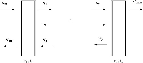
The equations for the steady-state fields are:
| (2.73) |
where is the phase gained (or loss) by the field in transit from mirror to mirror (it includes the axial phase shift and the Guoy phase shift). The resulting field are
| (2.74) | ||||
| (2.75) | ||||
| (2.76) |
The circulating power, , stored in the cavity is given by
| (2.77) | ||||
| (2.78) |
where we have introduced the Fabry-Perot gain and the Airy function . The maximum stored power corresponds to the peak of the Airy function, i.e. when the detuning phase , where is an integer. The detuning phase can be changed to match the resonance condition both by varying the length of the cavity and/or the frequency of the input light. The half-width of the resonances is determined by the finesse, F, of the cavity
| (2.79) |
The finesse is also related to the effective number of round-trips of the light inside the FP cavity by and to the storage time of the cavity by .
Chapter 3 Analytic and Numeric investigation of Optical Cavities
3.1 Duality Relation
3.1.1 Introduction
We discuss here a duality relation between deviations from sphericity (or planarity) of mirrors in FP cavities. This duality proved a key point for our theoretical and experimental studies of cavities with non gaussian beam profiles Duality . In his recent work on a tilt instability for advanced LIGO interferometers Savov-Vyat , P. Savov discovered numerically a unique duality relation between the eigenspectra of paraxial optical cavities with non-spherical mirrors: he found a one-to-one mapping between eigenstates and eigenvalues of cavities deviating from flat mirrors by and cavities deviating from concentric mirrors by , where need not be a small perturbation. In the following section, we analytically prove and generalize this result. In this work, we prove this remarkable correspondence analytically, for an even broader category of cavities: those whose mirror shapes remain invariant under the parity operation, identified as spatial reflection in the two dimensional -space (which is also equivalent to a rotation around the cavity axis). Eigenmodes of such cavities can be put into eigenstates of parity, and we show that all corresponding eigenmodes of dual cavities have the same intensity profiles at the mirrors, with their eigenvalues satisfying
| (3.1) |
where is the parity of the th eigenmode; subscripts c and f denote nearly concentric and nearly flat mirrors, respectively. We then illustrate its application to interferometric gravitational-wave detectors; in particular, we employ it to confirm the numerical results of Savov and Vyatchanin for the impact of optical-pressure torques on LIGO’s Fabry-Perot arm cavities (i.e. the tilt instability), when the mirrors are designed to support beams with rather flat intensity profiles over the mirror surfaces. This unique mapping might be very useful in future studies of alternative optical designs for LIGO interferometers, when an important feature is the intensity distribution on the cavity optics. While such a duality relation is well-known between cavities with spherical mirrors, i.e., those with (for example see Gordon ; siegman ; KL ), to our best knowledge no such relations had been established between generic cavities. In the following sections we present the work done in collaboration with E. D’Ambrosio. Another interesting approach to the duality relation was formulated by P. Savov and Y.Chen and is presented together with ours in a joint paper Duality .
3.1.2 Analytical proof for mirror-to-mirror propagation
3.1.2.1 Cartesian Coordinates
In this section we focus on field distributions on mirror surfaces, and restrict ourselves to cavities with two identical mirrors facing each other. The extension to the non symmetric cavity is presented later. We adopt the Fresnel-Kirchhoff diffraction formula to propagate fields from mirror surface to mirror surface (see e.g. Fox-Li ). In this formalism, the field amplitude on the surface of mirror 1 propagates into
| (3.2) |
on mirror 2, via the propagator
| (3.3) |
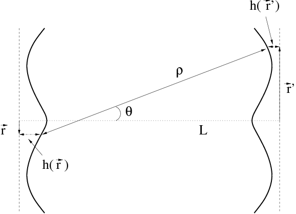
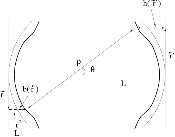
from (on mirror 1) to (on mirror 2), where denotes the (3-D) spatial distance between these two points and stands for the angle between the cavity axis and the reference straight line, as is illustrated in Fig. 3.1(a). We know that the Fresnel-Kirchhoff integral eigenequation
| (3.4) |
univocally determines the eigenmodes and eigenvalues of the cavity.
Applying the paraxial approximation
| (3.5) |
and we can use
| (3.6) |
in the integral eigenequation.
Here the mirror surfaces deviate by from a flat reference, and the subscript f is used to reflect this convention. From here on, we will also refer to as the nearly flat propagator. We now consider two slightly deformed concentric mirrors (see Fig. 3.1(b)) so that the mirrors height with respect to the flat reference surface is
| (3.7) |
where the height is the deviation from the concentric spherical surface (note that concentric spherical mirrors have their radii of curvature equal to , and thus surface height ). Inserting Eq. (3.7) into Eq. (3.5), we obtain the propagator for a nearly-concentric cavity,
| (3.8) | |||||
We use the term nearly concentric propagator for . Although we use the terms nearly-flat and nearly-concentric, and are not required to be small; in fact, they can represent any deviation from perfectly flat and concentric spherical mirrors.
Now let us consider mirrors that are then invariant under parity, i.e., those in which we also have
| (3.9) |
so that are both invariant under a spatial reflection
| (3.10) |
and therefore, we have
| (3.11) |
where we have defined
| (3.12) |
for two dimensional reflection. Equation (3.11) implies that all eigenmodes can be put into forms with definite parity. We derive the following relation between nearly flat and nearly concentric propagators, as constructed:
| (3.13) |
that is equivalent to:
| (3.14) |
Suppose we have an eigenstate of , i.e., an eigenstate of a cavity with mirror deviating by from flat surface, and we compute its eigenvalue and know the parity eigenvalue :
| (3.15) | |||||
| (3.16) |
By applying Eqs. (3.14)–(3.16), we derive the correspondance
| (3.17) |
which identifies as the corresponding eigenstate of , that is eigenstate of the corresponding resonator we denote the dual. The eigenvalue is . We also induce that the parity is still . The reverse is straightforward and the result is an established one-to-one correspondence between dual cavities. We summarize this mapping in Table 3.1. It is obvious to note that the corresponding eigenstates, and , have the same intensity profiles on the mirror surfaces; for infinite mirrors, we know is real-valued (see Appendix b of Duality ), so it is an eigenstate of the dual configuration itself.
Nearly Flat Nearly Concentric Kernel Eigenstate Parity Half-trip eigenvalue Round-trip eigenvalue
For cavities with identical mirrors facing each other, the full, round-trip propagator is just the square of the half-trip one. From Eqs. (3.13) and (3.11), we have
| (3.18) |
which means that the same duality correspondence exists between eigenstates of the full propagator, with their eigenvalues related by
| (3.19) |
3.1.2.2 Cylindrically symmetric mirrors
In most LIGO applications, cavity mirrors still have cylindrical shapes: . This allows us to decouple radial and azimuthal degrees of freedom, and simplify the eigenvalue problem. We shall follow roughly the notation of KL .
We adopt the cylindrical coordinate system:
| (3.20) |
Since is now invariant under rotation along the -axis, all eigenmodes can be put into eigenstates of rotation:
| (3.21) |
Inserting this into the eigenequation (3.42) and performing analytically the angular integration we obtain the radial eigenequation
| (3.22) |
where for each angular mode number we have indexed the radial eigenstates by , and
| (3.23) |
is a symmetric radial propagator, in the nearly-flat description.111Here we have used , where is the th order Bessel function of the first kind. Since is symmetric, we obtain orthogonality relations between radial eigenfunctions:
| (3.24) |
Using Eq. (3.7) again, for a configuration with correction from concentric spherical mirrors, we obtain the radial kernel of the nearly-concentric description:
| (3.25) |
Comparing Eqs. (3.25) and (3.23), we obtain:
| (3.26) |
This is a radial version of Eq. (3.14); here we know explicitly that all -eigenstates have parity .
Following a similar reasoning as done in the previous section, for each angular mode number , we can establish a one-to-one correspondence between radial eigenstates of a nearly-flat configuration to those of the dual configuration:
| (3.27) |
The mapping of the eigenvalues are given by
| (3.28) |
Similarly, the round-trip eigenstates have the same correspondence, their eigenvalues related by
| (3.29) |
3.1.2.3 Duality relation for non-identical mirrors
In this section we will study the duality relation when the mirrors shapes are not identical, but each still symmetric under a rotation around the cavity axis. Since now the field distributions of eigenstates over the two mirror surfaces are not the same, we have to study the eigenvalue problem associated with the round-trip propagator, instead of the individual surface-to-surface ones. Nevertheless, we can still use the propagators (3.6) and (3.8) to build a system of integral equations relating field distributions and over the two mirror surfaces. [Throughout this section, we use the subscripts and to refer to quantities associated with mirrors and , respectively.] If the mirrors deviate from parallel planes by , we have:
| (3.30) | |||
| (3.31) |
where give the attenuation and phase shift experienced by the optical field in transit from one mirror to the other and
| (3.32) | |||
| (3.33) |
are the propagators from mirror 2 to mirror 1, and from mirror 1 to mirror 2, respectively. The equations (3.30) and (3.31) give the field at each mirror in terms of the reflected field at the other but they can be combined to form the round-trip equation which states that the field at each mirror must reproduce itself after one round-trip. In the following, we will add a subscript or to make a distinction between quantities related to the nearly-flat or nearly-concentric case.
| (3.34) | |||
| (3.35) |
where the common eigenvalue is given by and the round-trip propagators
| (3.36) |
In the nearly-concentric configuration, using kernels of the form (3.8) for the propagation from one mirror to the other and combining them as done for the nearly-flat configuration, we obtain the following nearly-concentric round-trip equation for the field distribution over the mirror (similar formulas for the mirror with the substitution throughout the argument).
| (3.37) | |||
| (3.38) | |||
where are the mirrors deviations from concentric surfaces. Using the assumed symmetry properties of the mirrors, the propagators for the nearly-flat and nearly-concentric cavity fulfills this relation
| (3.39) | |||||
3.2 Eigenvalues and FEM analysis
In the preceding section we have analyzed an important relation which is satisfied by optical cavities in terms of eigenvalues and eigenfunctions of certain integral operator. In real application to GW Interferometers it is necessary to evaluate the eigenvalues and optical modes in situation where the mirror are not spherical and/or the finite size of the mirror become important. A few examples will be given below. We developed our own calculus packages in order to compute the optical modes and frequency spectrum of a FP cavity with non-spherical mirrors, which will be described in Sec. 3.6. This package found valuable applications also in the analysis of parametric instability222Knowledge of the diffraction losses for higher order modes is important for predicting opto-acoustic parametric instabilities. These arise due to the resonant scattering of the cavity fundamental mode against test mass acoustic modes into other optical cavity modes , which satisfy the condition . The parametric gain for this process determines whether the system is stable or unstable . The parametric gain depends linearly on the quality factor with higher order modes, which, on the optical side of the interaction, depends inversely on the diffraction loss ParInst . Thus it is very important to be able to obtain accurate estimates of modal diffraction losses in the optical cavities.Barriga of advanced detectors, due to its capability of obtaining, in a very efficient333In term of computational time. Other approaches like FFT propagation could obtain the same results but requiring up to two orders of magnitude more time than the approach described here (depending on the finesse of the cavity). and precise way, the eigenspectrum of an optical cavity. The equation which is the object of the next sections is
| (3.42) |
where the 2-D vectors and are the coordinates of the projections of mirror-surface points on planes orthogonal to the cavity axis at the mirrors positions, is the round trip (or half round trip for symmetric cavity as Ad-LIGO) propagator and and are the eigenvalues and eigenmodes (field distribution over the mirror surface) of the optical cavity. If the cavity mirrors are not equals, there is one eigenvalue equation for each field on the mirror surface; for the first mirror we have
| (3.43) | |||||
where and are the heights of the two mirrors respect with two planes orthogonal to the optical axis and separated by a distance . The equation for the transverse mode at the second surface is obtained with the substitution . These equations can be solved analytically only in very special cases (i.e. confocal spherical resonators, that is , Boyd ). In general some approximated solutions are found using different approaches. The finite-element method (FEM) has become a very powerful tool for the approximate solution of boundary-value problems governing diverse physical phenomena. We developed some general numerical tools for the FEM analysis of optical cavities of interest for the GW community working on the optical set-ups.
3.2.1 Cylindrical symmetric cavity
We will now solve the problem stated above for a cylindrical symmetric cavity, which is of interest for the application on the ideal perfect optical cavities of the GW interferometers both in their present design with spherical mirrors and in new configurations recently explored. It is obvious that for standard spherical optics the height function is given by , where is the radius of curvature of the mirror. As long as cavity mirrors posses cylindrical symmetry, we can separate the radial and azimuthal degrees of freedom, and simplify the search for eigenmodes. We adopt the cylindrical coordinate system: . Since is invariant under rotation along the cavity axis, all eigenmodes can be written in the form of
Inserting this into the equation Eq. (3.43), and performing analytically the angular integration 444Here we have used , in which is the th order Bessel function of the first kind., we have the reduced radial eigen-equation ( is the mirror radius)
| (3.45) |
| (3.46) | ||||
where for each angular number we have indexed the eigenstates by which is the radial mode number.
The problem is thus reduced to a series of one-dimensional integral equation, one for each . These are homogeneous Fredholm equations of the second kind and there are well documented standard techniques for their numerical solutions LD ; KA .
There are two general methods of solving (3.45). One is based on iterative techniques applied to a discrete grid that extract the dominant or several of the lowest-loss modes; the classical Fox and Li algorithm falls in this category.
For stable resonators the iterative method usually converges slowly because even higher-order mode losses are quite low. The second method, called Nyström method, requires the choice of some approximate quadrature rules in order to reduce the integral equation to a matrix eigenvalue problem of dimension equal to the number of integration points . The matrix method has two main advantages: it extracts the lowest N modes and their eigenvalues at one time, and its accuracy is determined by the order of the matrix. It is certainly possible to use low-order quadrature rules like trapezoidal, mid-point or Simpson’s rules, but since we are looking for a quite accurate solution of the eigenvalue problem (the modulus of the eigenvalues must be calculated with high precision for a realistic estimation of the diffraction losses) this would require a large number of integration points and therefore a lot of computation time. We used the Gaussian quadrature rule in order to have a greater accuracy with fewer points.
Typically, the value of the radial coordinate is bound by the radius of the mirror. We denote as this maximum value. Let be the abscissas and the weight factors for Gauss Legendre quadrature in the range . This technique has fine meshing at the edges of the computational window and more course meshing in the center.
The equation (3.45) for a certain can be approximated as
| (3.47) |
Defining the vector and the matrix we have transformed the integral eigenvalue problem Eq. (3.45) to a matrix eigenvalue problem which can be solved for and by any standard mathematical package. The convergence of the eigenvalues and eigenvectors of the discretized problem to those of the continuous eigenvalue equation (3.45) for sufficient large is guaranteed by mathematical theorems Atkinson .
Once the eigenvectors are determined, a particular mode may be evaluated at any point (not a sample point) by calculating the sum555This formula has been demonstrated to be the best interpolating function between the grid points. This is called Nyström interpolation formula.:
| (3.48) |
The complex eigenvectors correspond to the resonator mode patterns at the first mirror surface. The fractional power loss per transit of the mode due to diffraction effects at the mirrors is given by . As is usual in optical resonators, the eigenvalues can be sorted in decreasing magnitude order. The phase shift is given by the angle of , which is the phase shift suffered (or enjoyed) by the wave field in a roundtrip. The resonant condition requires that the total phase shift along the axis of the cavity be an entire multiple of rad; thus, separating the longitudinal phase shift666The minus signs are due to the sign convention in the propagator., . The resonance frequencies of the axial-plus-transverse modes in the cavity is given by
| (3.49) |
where is the free spectral range of the cavity, i.e the frequency spacing between successive longitudinal resonances. We implemented the described procedure in a program, using its built-in routines for the solution of eigenvalue problem777As a technical remark is useful to point to the fact that when diffraction losses are very small, i.e. when the absolute value of the eigenvalues is close to one, it may be necessary to increase the significant digits in all the computations and one of the advantage in is that it can handle approximate real numbers with any number of digits..
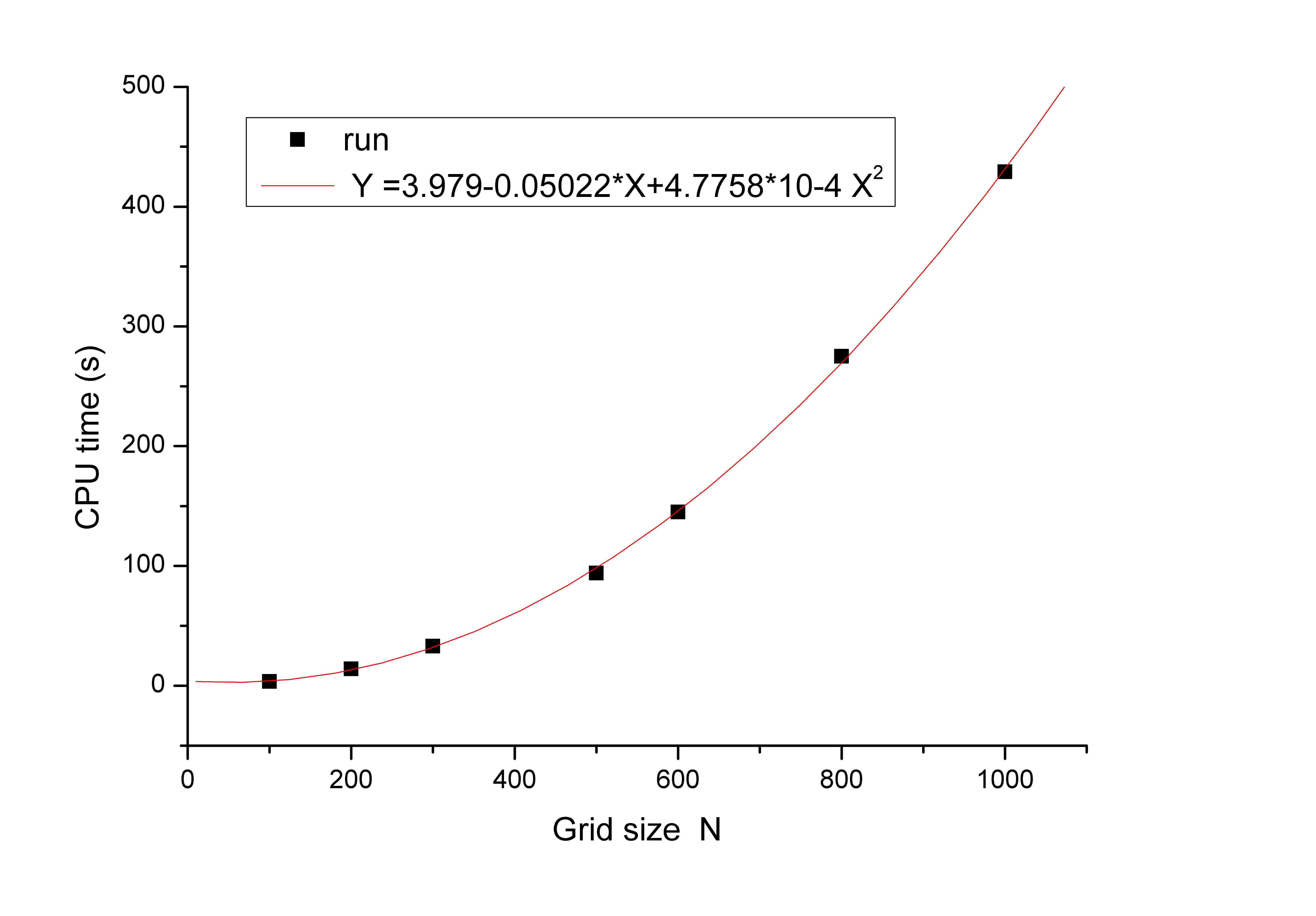
In Fig. 3.2 we show that the CPU time for the computation of ten eigenvalues as function of the grid size . The advantage of using the Gaussian quadrature rule is evident if we consider that a grid nodes in an equal spaced mid-point rectangular quadrature rule can achieve an accuracy of in the magnitude of the eigenvalues; by comparison a Gaussian quadrature rule with nodes reaches an accuracy of in the eigenvalue magnitude value.
3.2.2 Advantages with respect to iterative method
The advantages of the eigenvector method are:
-
•
The propagation matrix has to be calculated only once, then the main task is to solve the set of eigenvalues of the transit matrix, and each eigenvalue can directly derive one set of eigenvectors, which just represents one mode distribution on the mirror, without hundreds of iteration.
-
•
Phase shift and amplitude loss per roundtrip can be easily evaluated from the eigenvalues.
-
•
The multi-modes can be obtained with a single calculation.
-
•
There is no need of an initial field distribution, which has to be carefully given in the Fox Li or in the Prony method to get the convergent results.
As an example of the capabilities of this simulation tool let us mention the use in the calculation of realistic diffraction losses in the Ad-LIGO FP cavities, for the estimation of parametric instability. In eleven lines of Mathematica® code we are able to compute the diffraction losses of ten higher order modes in less than four seconds of CPU time using grid nodes. Barriga et al. Barriga used an iterative process based on FFT algorithm, which requires one hour888Barriga in private communication. of CPU time for the computation of each mode diffraction loss. As it is shown in Fig. 3.3, the agreement between the two calculations is very good with a maximum deviation of around due to intrinsic limitation of the FFT algorithm for this kind of analysis.
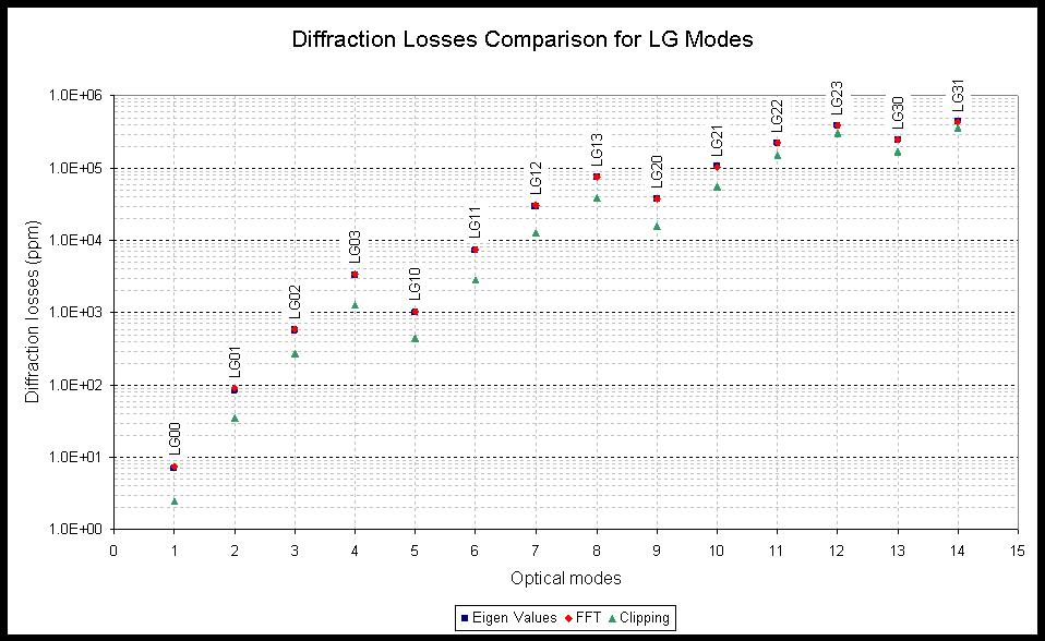
3.2.3 Arbitrary mirror shape
In the preceding paragraph we analyzed the problem (3.43) in the very special case of cylindrically symmetric mirrors and ideal mirrors with no imperfection. In real application, we have to analyze broader situations, where the mirrors deviate from the ideal shape by some amount,i.e. intrinsic manufacturing defects or deformations due to thermal effects. It is thus very useful to have an algorithm to solve Eq. (3.43) without the restriction of Sec. 3.2.1. In literature there are two well known technics for approximate solution of this problem both based on iterative procedure; to find the steady-state mode distribution, an arbitrary initial wave distribution is propagated repeatedly around the resonator,undergoing changes from transit to transit and loosing energy by diffraction. After many iterations, the wave converges to a steady-state stationary mode. In one case the propagation between mirrors was carried out by expanding the optical wave in an eigenfunction expansion using as a basis set the Hermite-Gaussian beam functions characteristic of free-space optical beam propagation. Because these functions are normal modes for free-space propagation, this basis set has both conceptual and computational advantages, as demonstrated in SiegmanMODE . However, this expansion has also the same practical disadvantage characteristic of most such normal mode expansions. If one expands a discrete point two-dimensional function in an series of basis functions, the amount of computation required goes up in proportion to , or in proportion to if . The other approach, SiegmanFFT , is based on a Fast Fourier Transform algorithm to compute the propagation between the surfaces and will be described in more details in the next Section. The FFT method has the advantage of requiring a smaller computational effort which increase as respect with the of the other iterative approach in the real space. Nevertheless if the diffraction losses are small, the iterative process could converge very slowly and require a long computational time. For this reason we developed a procedure for the calculation of the eigenmodes, that reduce the problem (3.43) to a matrix eigenvalue problem which can be solved by standard numerical routines. The problem is that in a simple discretized version of (3.43) over two grids, one for each mirror, we have an equation between matrix related by a kernel. We use the following trick to reduce it to a standard matrix problem. First we choose a numerical integration rule for the evaluation of integrals in a compact bi-dimensional domain (mirror surface). We will use, for simplicity, a mid-point rectangle quadrature formula,999The extension to more efficient quadrature formulas in polygonal domain is quite straightforward. such that the mirror is sampled at equally spaced points in the coordinates and assume that the mirror have equal radii . We first select the dimension of the grid and the spacing between nodes in this grid
| (3.50) |
It is however a waste of memory to keep track of the node points that fall outside the mirror boundary; we therefore build a , with matrix, that contains only the coordinates of cells inside the mirrors
| (3.51) |
The equation (3.43) is then reduced to the matrix equation
| (3.52) |
where the matrix is given by
| (3.53) |
This eigenvalue equation can be solved by any standard mathematical package. We implemented the above described routine in a code because of its efficiency in dealing with large matrices. With respect to the grid of dimension , the size of the matrix increases as , requiring a notable amount of memory to store its values and compute the eigenvectors.
3.2.4 Constraints on FEM analysis
It is interesting to point out some constraint of FEM analysis applied to Eq.(3.43) since it is often an overlooked aspect in papers related to this technique for optical simulation. The grid size is set by a compromise between accuracy of the calculations and computational effort required. The kernel in the integral equation is a rapidly oscillating function of the coordinates and sampling it at the grid nodes introduces inevitably some errors. A faithful discrete representation of this function is obtained applying a sort of sampling theorem of signal analysis. The fundamental constraint is that the phase difference between two adjacent point must be less than . There are two contribution to this phase, one independent on the mirror profiles and the other directly given by the height of the mirrors. They give the following constraints on the maximum spacing allowed between grid nodes
| (3.54) |
These constraints set, for a given quadrature rule, the number of minimum grid points; it is important to point out that the first constraint is determined by the laser wavelength and the cavity length, whereas the second constraint is set by the mirror geometry and the laser wavelength. Once these minimum requirements are fulfilled, a further increase in results in a better accuracy in the extraction of the eigenvalues and eigenvectors.
3.3 FFT
A new package based on was developed to simulate an optical cavity when realistic mirrors are included. It can moreover deal with many features including mirror tilts and shifts, beam mismatch and/or misalignment, diffractive loss from finite mirror apertures, mirror surface figure and substrate inhomogeneity profiles, in particular, using deformation phase maps that are adapted from measurements of real mirror surfaces and substrates, as well as fluctuations of reflection and transmission intensity across the mirror profiles. Similar programs VinetFFT ; Bochner developed by many other research groups, have been used for a variety of applications by the gravitational wave community, including numerous design help and performance estimation tasks. We decided to build our own code because we needed a fast and reliable tool for the optical simulation of our mesa beam cavity; the time we would have spent in learning and modifying the existent programs was employed to write and debug our own code. Incidentally, thanks to its simplicity and versatility, the programs revealed itself very useful for investigations related to Ad-LIGO and Virgo thermal compensation system.
The required procedure is to expand the propagating wave at any given plane into a series of plane-waves or spatial- frequency components, travelling at different angles in space. The component plane waves are propagated from one transverse plane to the next by a simple propagation formula, Eq. (2.12). The transformations from coordinate space to space and back again are formally equivalent to Fourier transformations, Eq. (2.10), and can be very efficiently carried out using the fast Fourier transform (FFT) algorithm. Fourier transformation carried out using the fast Fourier transform (FFT) algorithm provides the opportunity for a significant increase in computational efficiency. The computational labor required to expand a two-dimensional function in a two-dimensional Fourier expansion only increases as , which is a much smaller number than for moderate-to-large values. However, propagation from plane to plane is not sufficient for our purpose. In general we need to represent the propagation from the surface of one mirror to the other, which could be of standard spherical shape, or even non-spherical as we will see in Sec. 3.6. One fundamental point for the application of this algorithm is that the action of a mirror on the optical field, can be modelled without using a diffraction integral. Following VinetFFT it is convenient to discuss this issue in the Fourier space. If is the field in the plane , and the field on the mirror surface, we have
| (3.55) |
The argument of the imaginary exponent can be expanded keeping in mind that we are dealing with paraxial optics
| (3.56) |
In order to estimate the order of magnitude of the second term with respect to the first one let us remind that the divergence of a beam is defined as the second moment of the Fourier transformed field, Eq.(3.68); Therefore we have
| (3.57) |
where we have used the definition of the generalized Rayleigh range introduced in Sec. 2.7. Since the second term is a factor smaller than the first one, we can conclude that for surface height , with good accuracy we can write
| (3.58) |
The expression of the field on the mirror surface of equation is related to the field at a reference plane by
| (3.59) |
with this approximation is obvious that the reflection and transmission operators from a mirror with non planar surfaces are described by
| (3.60) |
where and are the ordinary scalar amplitude transmission and reflection coefficients and and are the functions representing the local phase change due to reflection or transmission trough a mirror (these functions depend on the mirror surface shape and on the material refraction index).
Therefore we can represent propagation in free space by a phase factor in the Fourier space according to equation (2.15), and the interaction with a mirror by phase factors in the direct space.
A simple FP cavity like Fig. 2.4 can be thus modelled using just multiplication of elements of matrices and FFT routines. For example the intra-cavity field obeys the steady-state equation
| (3.61) |
where indicate the Fourier transform, is the propagator down the cavity length , the reflection operators distinguish between right or left incidence and is a uniform phase added to achieve the fine tuning of the cavity (it plays the same role as a microscopic length change). Let us assume that we choose a square grid in the real space of dimension and the corresponding grid in the Fourier space. Thus each mirror reflection or transmission operation is reduced to a pixel-by-pixel multiplication between a mirror operator map and the e-field slice on the reference plane near to it; the propagation between two mirrors is given by an FFT, followed by a element-by-element multiplication between the transformed matrix and the matrix, and then an inverse FFT. The simulation program models a static optical cavity, which means that we do not follow the time evolution of the field inside the cavity but we iterate the equation (3.61) until a steady-state is obtained for the field. The simple field relaxation algorithm requires a pre-specified threshold of accuracy: the iteration process ends when the field calculated at the iteration is equal, within the accuracy requested, to the field calculated at the iteration. Other more sophisticated relaxation algorithm are described in Bochner and will not be adopted in this work.
3.3.1 FFT limitations
The propagation calculation using FFT procedure require proper attention to questions of sampling and aliasing. These problems have been deeply discussed in Bochner and we will point the fundamental issues. Let being the mirror radius and consider a square grid of dimension and side length which contains the mirror at its center101010For the moment we do not set a constraint on the relative size . It will be a crucial point in the aliasing discussion later.. Let being the spacing, in the directions, between the grid nodes (). These parameters set the k-space grid length and spacing
| (3.62) |
It is well known that sampling a function which has power at spatial frequency above the Nyquist frequency, , causes aliasing. One possible solution is increasing the highest spatial frequency in order to push this limit above the spectral distribution of the function. To quantify the requirements for the -space gridding, let us remember that gives the propagation direction of one Fourier component (plane wave) and that the beam divergence, is the second moment of the Fourier transformed field. In paraxial beam propagation, the k-spectrum of the beam is therefore limited by , where is a constant of order unity. The maximum propagation angle and the -resolution pose the following constraints to the grid choice
| (3.63) |
Remembering that for a generic paraxial beam, , we see that the second constraint is easily satisfied, but the first needs some care: it requires a large number of grid nodes but also constrains the resolution of the grid by . It is moreover important to consider the aliasing effect due to large-angle scatter from mirror deformations: a very simple way to take care of the power scattered by one fourier cell into the next replica, is to increase the window size well above the mirror diameter, and apply the so called ”zero-padding” method. It simply forces to zero the power outside the mirror surface. We thus have that for most application, is a good choice. There is also another aspect that has to be considered among this program constraints. Since the actions of the mirror are represented by pixel-per-pixel phase multiplication, the optical path difference between two neighboring pixels must be smaller than . This sets some limitations on the mirror shape and tilt we are able to simulate with a given grid finesse. For our optical cavity (m, mm, cm) we have the limitation mrad on tilt we can model.
3.4 Mesa beam
3.4.1 Introduction
The fundamental Gaussian has great flexibility, is used in many applications, and has an easy and attractive mathematical form. Nevertheless, many cases require different intensity profiles: a cylindrical volume with a diameter is just a quarter filled by a gaussian intensity distribution, therefore a gaussian beam is not appropriate for high power laser applications. The case of interest here is that of the reduction of thermal noise of mirrors. Most gravitational wave interferometric detectors (GWID) measure the variation in phase between light beams resonating in two perpendicular cavities caused by the passage of a gravitational wave. Any physical displacement of the reflective surfaces of the cavity mirrors also creates phase variations and thus contributes noise to the measurement. In particular, random displacements of the test masses’ reflective surfaces due to thermodynamical fluctuations is a major source of fundamental noise in the frequency range of maximum sensitivity for next generation interferometers (Fig. 1.3).
Gaussian laser beams are typically used to measure the position of the mirrors in these new detectors. Because of the peaked nature of the gaussian beams, they are not well suited to average over the localized thermal fluctuations. It is possible to significantly reduce the test mass thermal noise using modified optics (“graded-phase mirrors belange1 ”) that reshape the beam from the conventional gaussian intensity profile into a flat-top beam profile. Similarly, flat topped beams would be of interest to reduce mirror thermal noise in metrology and in frequency and distance standards.
One set of potential beam profiles that satisfy the request of a flat-top, more uniform transverse power distributions, is given by the supergaussian functions, with analytical form . Such a field pattern can be obtained shaping a gaussian beam with a diffractive optic, and use a refractive lens to produce a focused flat top intensity. In the case of gravitational wave interferometers, the optimized displacement sensitivity also requires very small diffraction losses ( ppm per bounce) in their Fabry-Perot arms. This precludes ordinary refractive techniques to flatten the resonant beam shape in the cavities. It was shown that certain optical resonators formed by two facing graded phase mirrors - i.e. aspherical mirrors - can have a fundamental mode with supergaussian features belange2 . The mirror profile, in this case, can be designed to match the phase wavefront for a prescribed intensity profile, while maintaining small diffraction losses. A different analytical approach to design flattened beam was proposed by Gori Gori : the flat top beam can be obtained as a sum of Laguerre Gauss modes in the cylindrical coordinate system. The main advantage of such transverse field distribution is that the field that they produce upon propagation can be evaluated in a simple way without introducing any approximation except, of course, that the paraxial regime is assumed to hold. Tovar Tovar has proposed a new class of beams, called multi-Gaussian beams, that can reproduce the flatness of a super-gaussian transverse field. They consists of a small sum of finite-width gaussian beams side by side with the same width, phase curvature and absolute phase. Unlike the flattened Gaussian beams, each of the multi-Gaussian beam components can be traced individually without resorting to further series expansion. Hence, this approach has an analytical form more desirable to study the beam diffraction characteristics.
Furthermore, beam propagation must be exactly known in order to characterize interferometer performances.
Thorne and others proposed and theoretically studied reducing ; oshaug ; erika the possibility of using a particular class of aspherical mirrors, the so-called “Mexican-hat” (MH) mirrors, in a Fabry-Perot cavity to generate a wider, flat top laser beam, the mesa beam. Such a beam is predicted to significantly reduce all sources of test mass thermal noise by better averaging over its surface fluctuations reducing ; oshaug ; erika ; Aspen ; VinetFB ; TNmeeting . A complete analysis of this problem will be given in Sec. 4.8.
3.4.2 Mesa Beam and Mexican Hat mirrors cavity
The mesa-beam must have an intensity distribution that is nearly flat across the light beam, and then falls as rapidly as possible (to minimize diffraction losses) at the beam’s edges. For a given length , and laser wavelength there is a particular Gaussian beam, called minimal-Gaussian beam, whose radius increases by a factor between the beam waist (at the cavity’s center plane) and the cavity’s mirrors, which provides a minimally spreading Gaussian beam. The mesa electromagnetic field,in a quasi-flat cavity, is a superposition of minimal-Gaussian fields whose axes are parallel to the cavity axis and lie within a cylinder of radius centered on the cavity axis. The (non-normalized) field distribution at the mirror plane is
| (3.64) |
where is the modified Bessel function of zeroth order and is the waist of the minimal-Gaussian (where k is the wavenumber). For a cavity to have the mesa beam as an eigenmode, the surfaces of the mirrors must coincide the mesa field’s surfaces of constant phase at that distance from the waist(this is true for infinite mirrors, but also a quite good approximation for finite mirrors if the diffraction losses are small). The resulting height distribution as a function of radius is given by
| (3.65) |
The resulting mirror’s radial profile is shown in Fig. 3.4(b) along with the spherical (nearly-flat) mirror profile which support a Gaussian beam with the same diffraction losses; notice the shallow bump in the middle and the flaring outer edges which resemble a Mexican hat (sombrero) and gave the mirror its name.
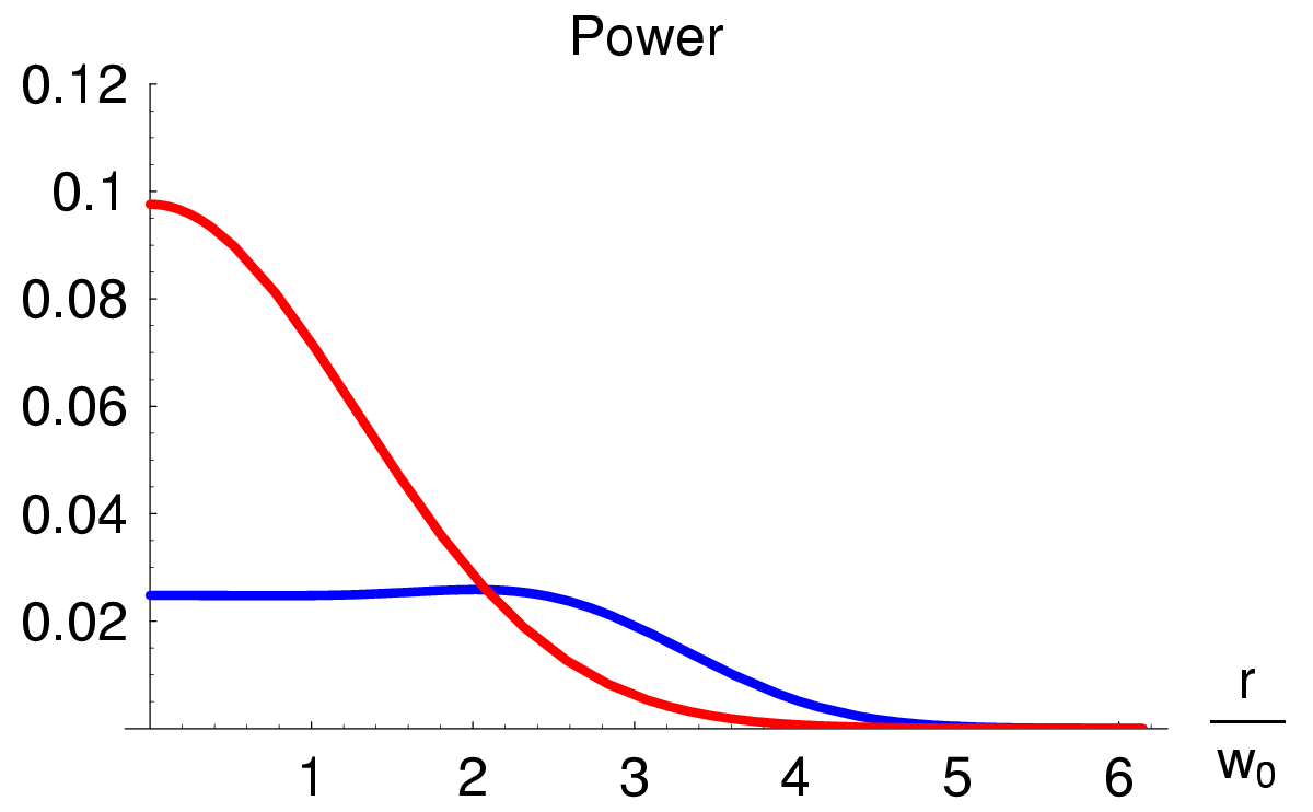
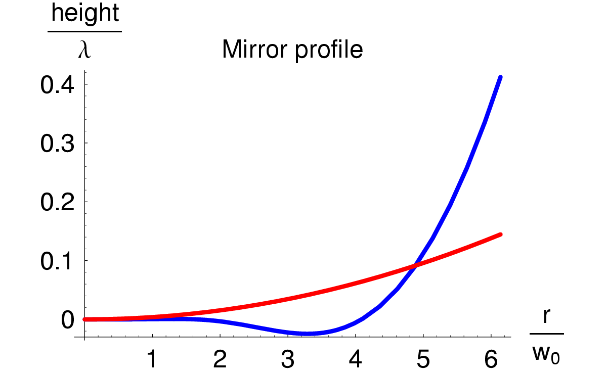
The corresponding optical design has shown strong tilt instability at high power Savov-Vyat than the corresponding Gaussian beam. K.S.Thorne proposed a different version of the mesa beam, that is supported by nearly concentric and opportunely shaped mirrors; this new version provides the same intensity profile at the cavity mirrors surface (and thus the same thermal noise), but introduces a weaker tilt instability (better than Gaussian beam cavities with the corresponding nearly concentric spherical mirrors analyzed by Sigg and Sidles sidles ) — as calculated by Savov and Vyatchanin Savov-Vyat and by us in Sec. 3.5.2. A general method to design a family of optical cavities has been proposed by Bondarescu and Thorne Bond-T , from nearly flat resonators to nearly concentric ones. This kind of mesa beam is constructed by coherently overlapping minimal Gaussian beams with axes in diverging directions sharing a common point at the cavity waist. The non-normalized field distribution at the waist plane (cavity middle point) is given by
| (3.66) |
This field can then be propagated along the optical axis using the Huygens propagator (2.37) adapted to a simple free space propagation. Examples of normalized power distributions of nearly flat and nearly concentric mesa beams are plotted in the upper panels of Fig. 3.5. In these plots, we take , which corresponds to the configuration proposed for Advanced LIGO .

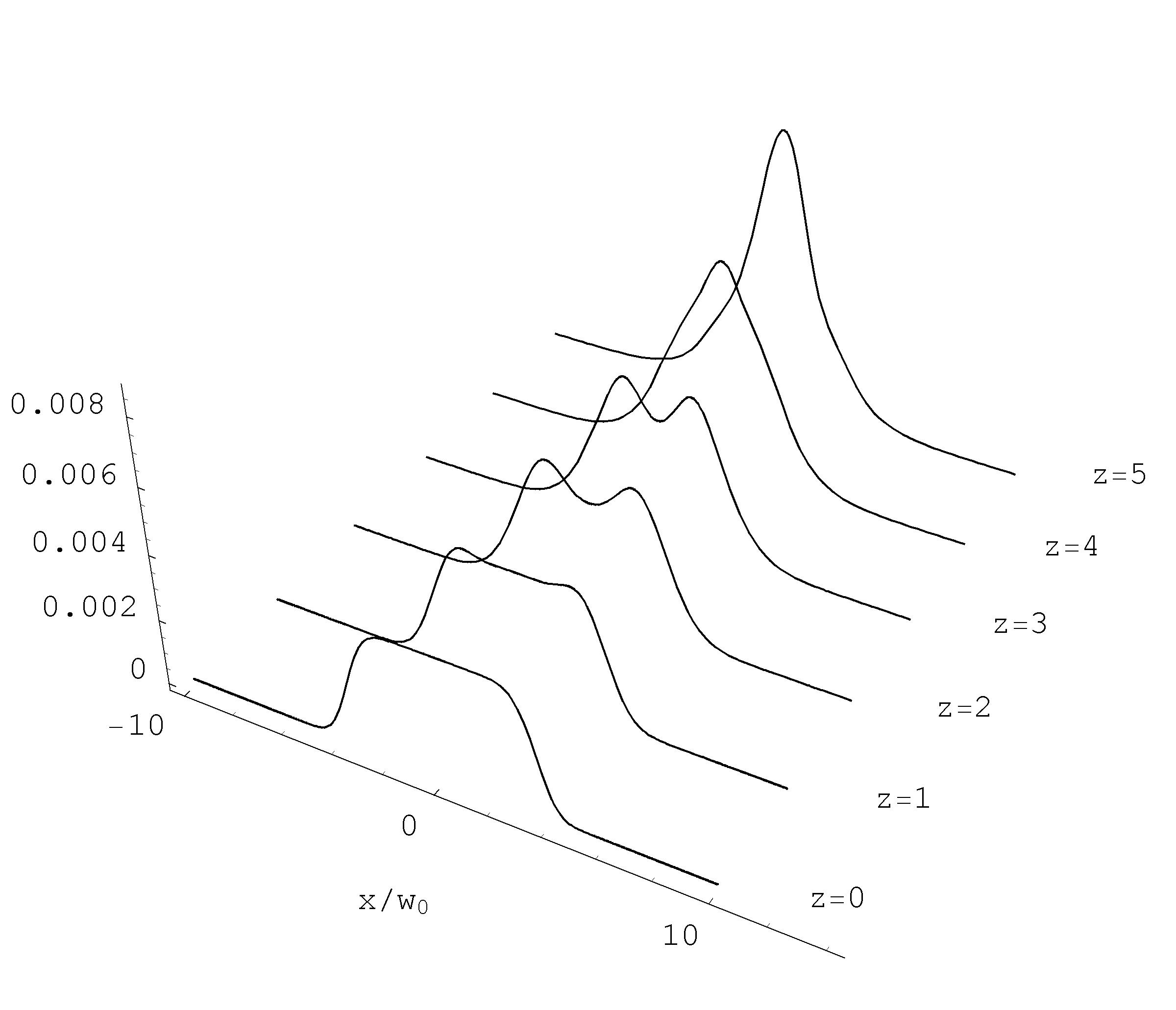
Even if the beam profile doesn’t conserve the same shape along propagation (see Fig.3.6 and 3.7), which is the case of Gaussian beam, we will show in the next section that is possible to characterize the beam trough the moments definitions of Sec. 2.7.
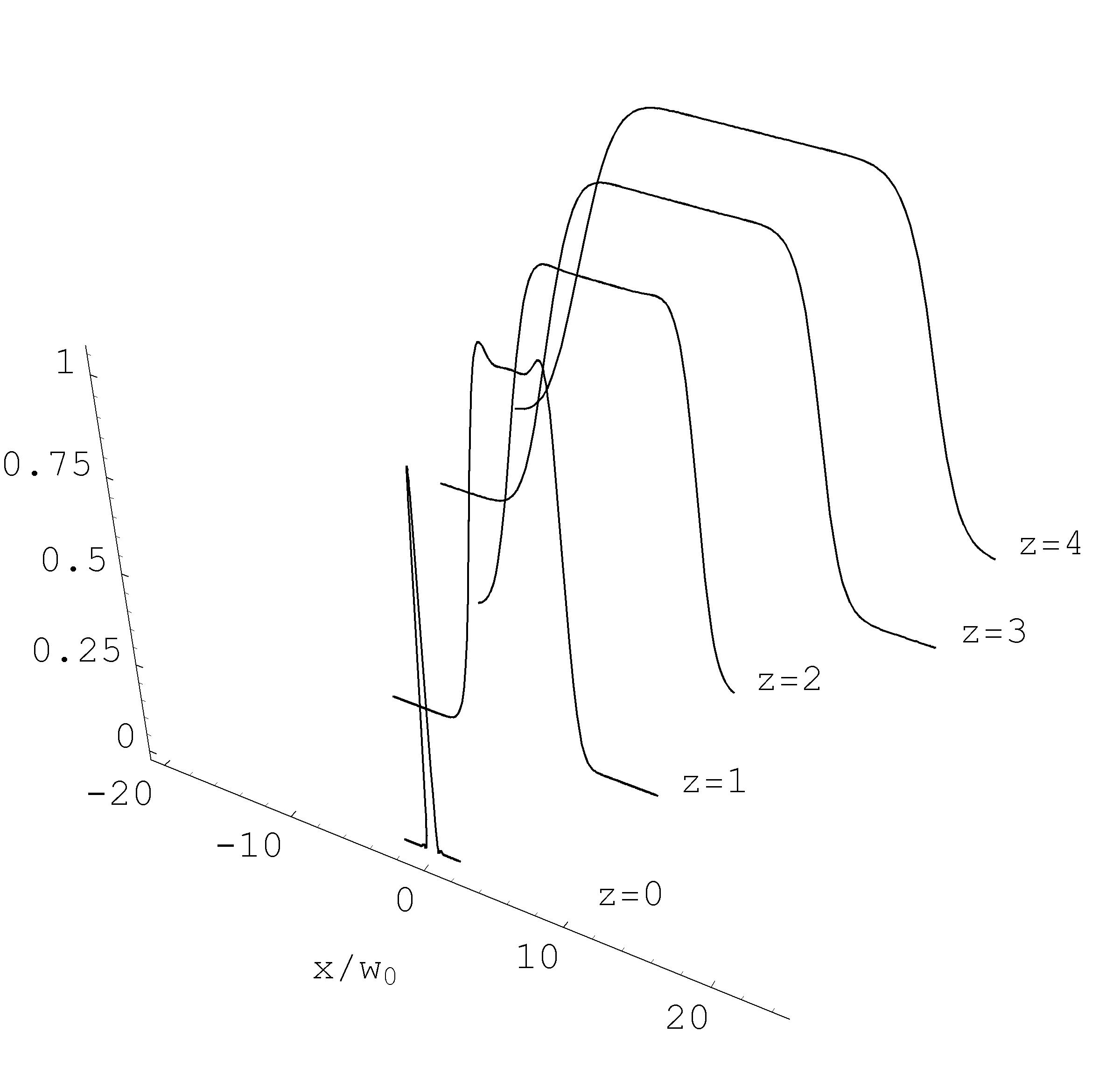
3.4.3 Analytical investigations of mesa beams
Mesa beam have been studied mostly numerically erika and Sec. 3.6.1.2, perturbatively oshaug ; reducing and Sec. or using an expansion on Gauss Laguerre functions Hyperboloidal . It is however of great utility to have some analytical formula for studying the beam characteristics and beam propagation trough an optical system without recurring to numerical analysis. In this section we follow the guidelines given in Sec. 2.7 for the definition of some parameters which are the usually measurable quantities (2.56) in an optical beam and which behave in a simple way under a generic transformation. The expression of the mesa field as given by equation (3.64) seems quite intractable from an analytical point of view, in particular the integral cannot explicitly computed. However it is a convolution product of a gaussian with the disc function of radius and in the Fourier domain this become a simple product of the transformed functions, which are well known. The first important step is to express the formula for the generalized beam width and radius of curvature in the Fourier domain. Since we are dealing with cylindrically symmetric problems it is useful to work with these definitions of Fourier transform and Hankel transform
| (3.67) | ||||
We recall here the formula of the generalized beam parameter assuming a normalized field 111111Note that the coefficient of the divergence contains different factors due to the different definition of the Fourier transform.
| (3.68) | ||||
| (3.69) | ||||
| (3.70) |
Using the definition (3.67) and the properties of Bessel functions is easy to prove the following equalities
| (3.71) |
It is then possible to express the equations (3.68) in a different way
| (3.72) | ||||
| (3.73) | ||||
| (3.74) |
First of all we need to find a normalization for our flat mesa (FM) beam (3.64) otherwise the above formulas are not analytically computable. We use the Parseval relation121212The same technique has been used in Virgo-Book . Our results confirms their calculation of the normalization factor and correct some errors for the Gaussian beam coupling efficiency calculated there. applied to the transformation (3.67) in polar coordinates
| (3.75) |
Lets consider the mesa beam (3.64) at the beam waist
| (3.76) |
Now, the Hankel transformation of the gaussian and of the disc function are well known
| (3.77) |
The integral of the intensity in the Fourier domain can be performed analytically
| (3.78) |
We have therefore the normalized field at the beam waist
| (3.79) |
The expression of the Fourier transformed field is
| (3.80) |
The expression of the FM beam in other plane along is just a straightforward application of the propagation rule for each Gaussian composing the beam. The calculation led the following result131313Omitting the phase factor common to all the minimal Gaussian given by the Gouy phase shift .
| (3.81) |
where is the Rayleigh range and is the beam radius at the plane of the minimal Gaussian field
| (3.82) |
The Fourier transformed field is
| (3.83) |
Using the expression (3.80) in equation (3.72) we can calculate the FM beam waist and the divergence .
| (3.84) | ||||
| (3.85) |
Using (3.83) with (3.72) we can calculate, at any plane , the beam width and the radius of curvature
| (3.86) | ||||
| (3.87) |
It is possible to verify that these quite complicated propagation rules can be put in the standard form
| (3.88) | ||||
| (3.89) |
3.4.4 Concentric Mesa beam
In the Concentric Mesa (CM) beam case, (3.66), we have the great advantage of having an explicit form of the field at the waist plane. The normalization is thus immediately performed using the same integral (3.78).
| (3.90) |
and the propagation is obtained using the Huygens integral (2.37) with .
| (3.91) |
It interesting to observe that the field has exactly the same for of the Fourier transformed . This is a manifestation of the duality relation between these two kind of beam; one beam is related to the other by a transformation which has the form of an Hankel transformation 141414Further details about this aspect of the duality relation are given in Duality . As seen for the FM case with equations (3.88) and (3.89) it is sufficient to calculate the beam waist and divergence to obtain the propagation formulas. For the CM it is more useful to work with the field (3.90) and use the first of (3.68) and the last of (3.72) for this computation. The results are
| (3.92) | ||||
| (3.93) |
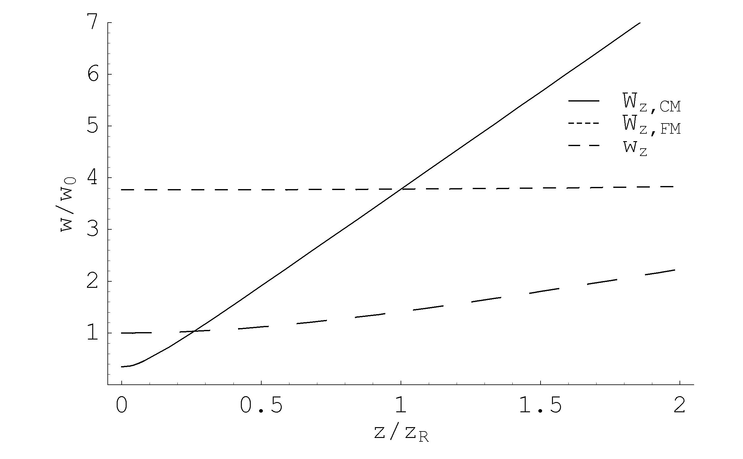
3.4.5 parameters and misalignment sensitivity
The parameter , introduced in (2.50), is an invariant of the beam along the propagation and is a very useful tool in beam propagation analysis. At the beam waist is given simply by151515For a pure Gaussian beam .
| (3.94) |
| (3.95) |
In Fig.3.9 is shown as a function of the integration disc radius .
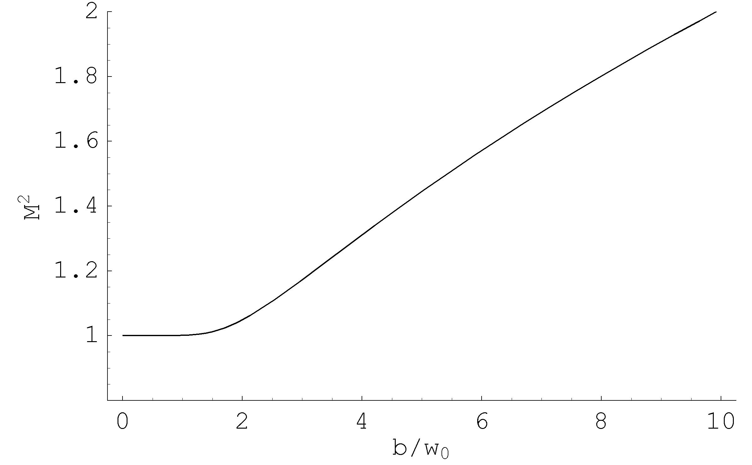
| (3.96) |
which is another manifestation of the duality relation.
The misalignment sensitivity of a generic paraxial beam is quantified by the misalignment factor introduced in Morin and briefly recalled on pg. 2.60 (where and represent the transverse and angular shifts, respectively, of the misaligned beam in a given plane). The misalignment superposition integral of Eq. 2.59 can not be analytically performed for FM and CM beams but the approximated expression Eq. 2.60 offers a good approximation for small misalignments.
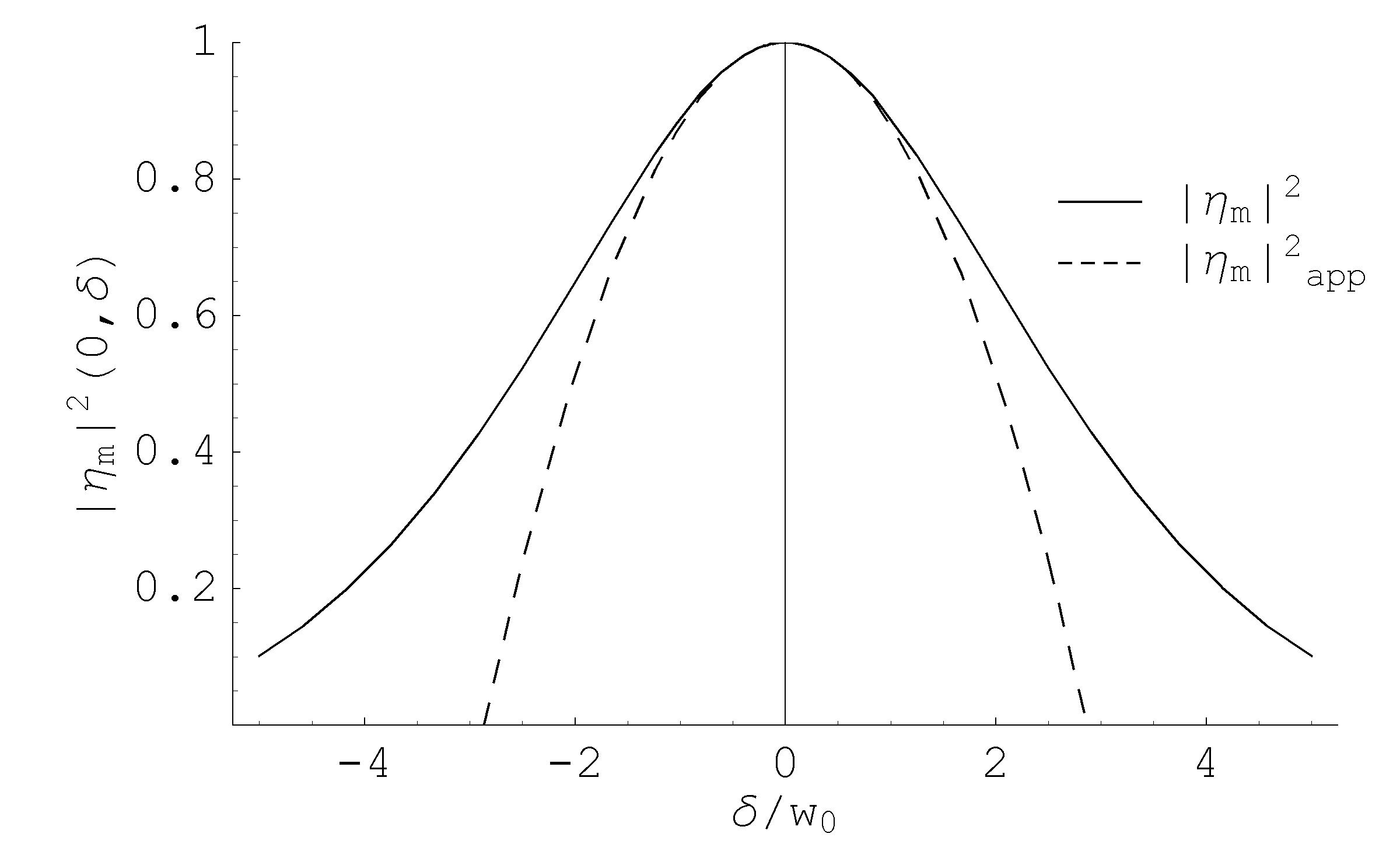
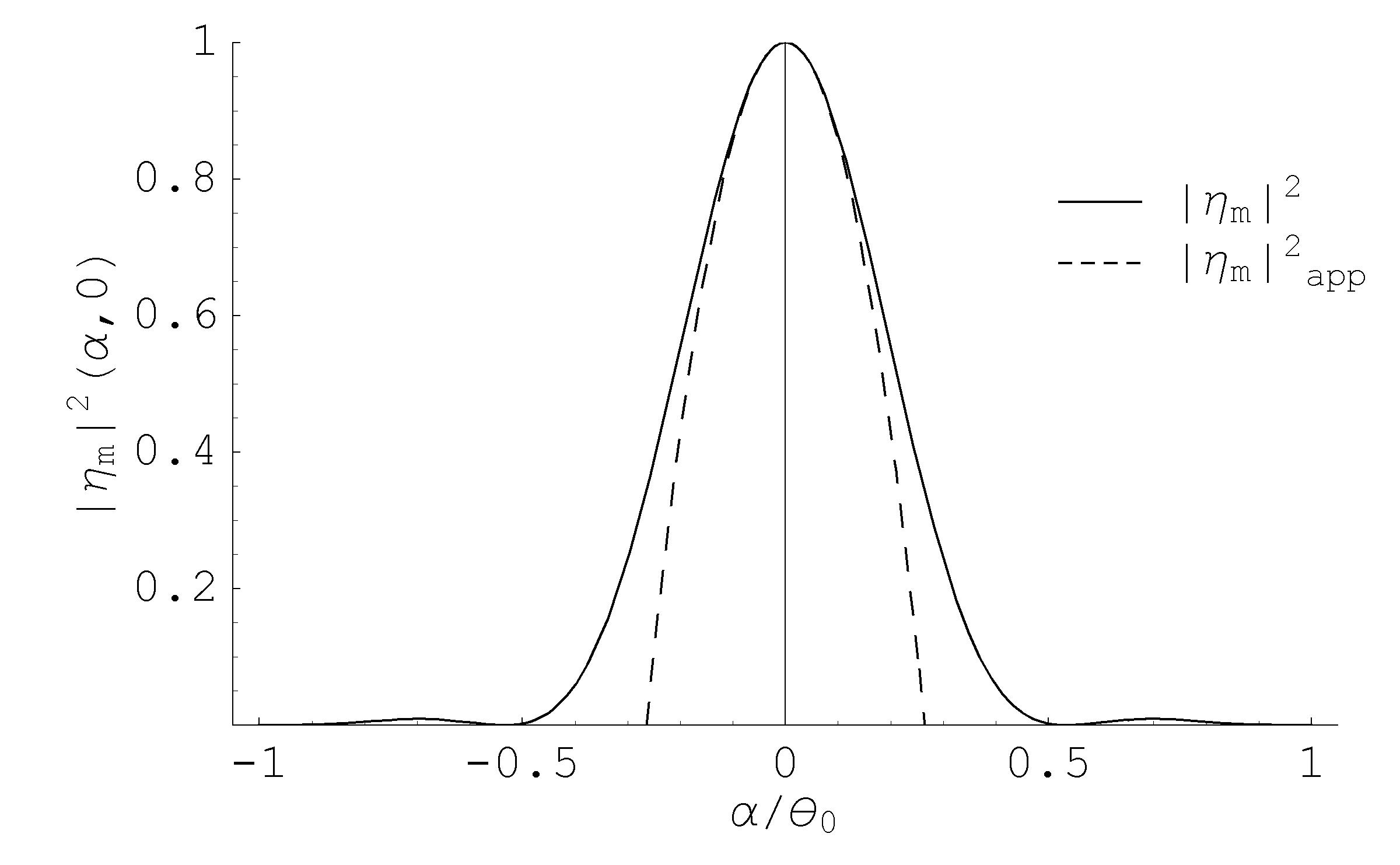
We will therefore continue the misalignment analysis using the approximated expression
| (3.97) |
where and are the beam divergence and beam waist respectively. This factor is trivially computable for Gaussian beam. To analyze the mesa beam misalignment sensitivity in both configuration, FM and CM, we plot in Fig. 3.11 the beam divergence and beam waist for different value of the constituent parameter .
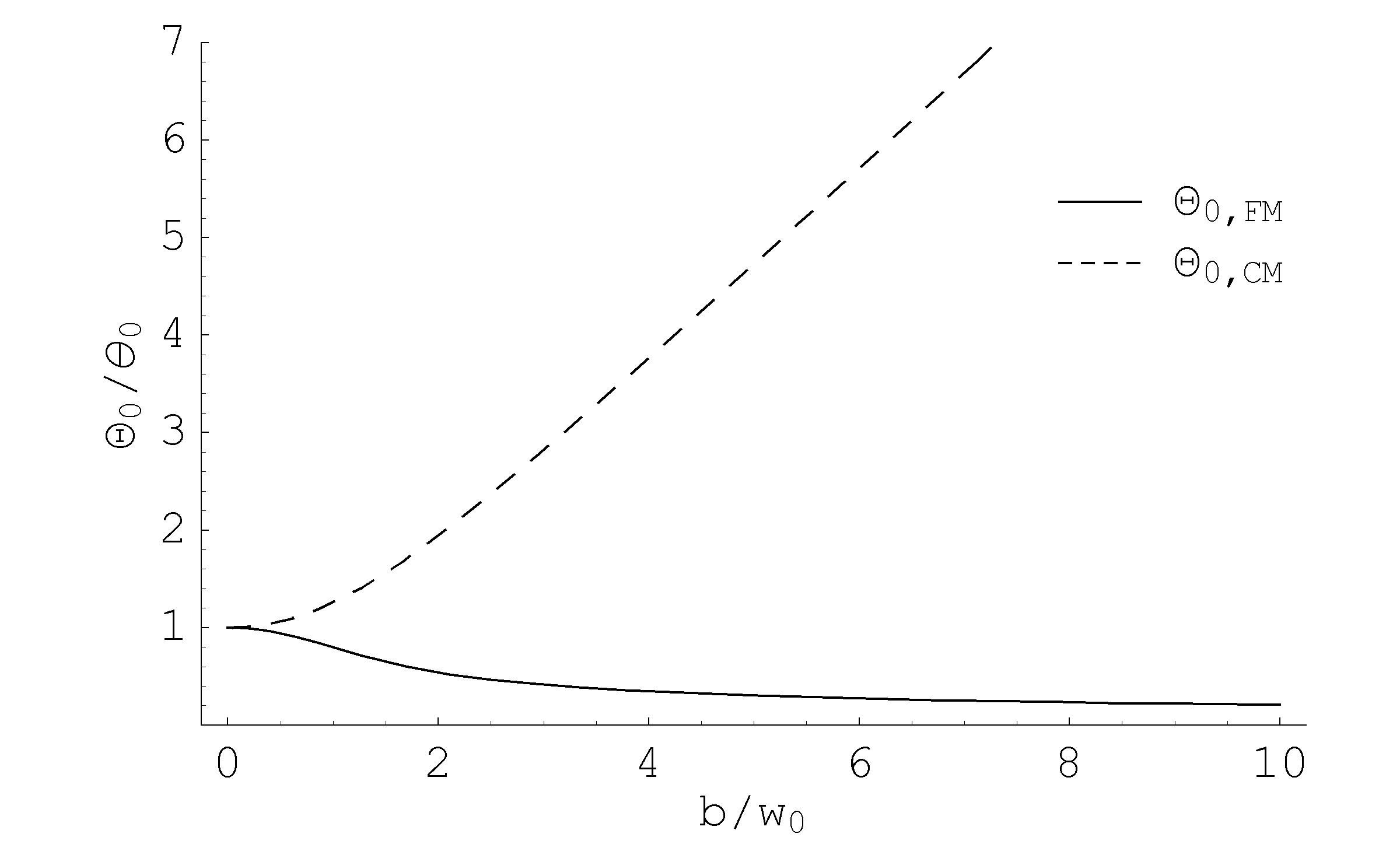
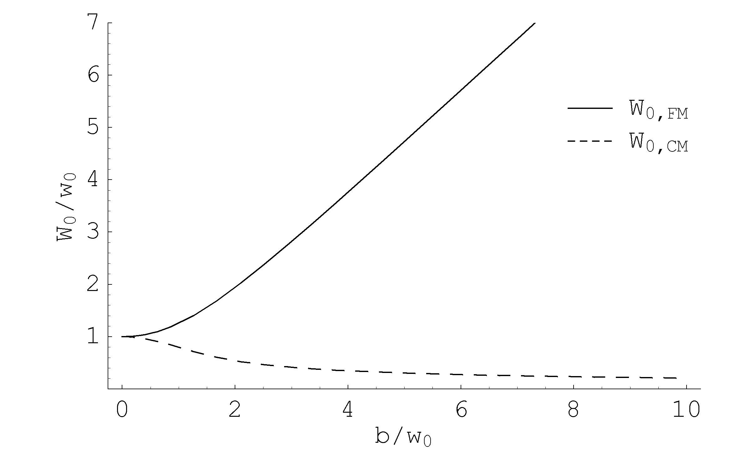
The misalignment sensitivity ratios between the FM and CM configurations are represented in Fig. 3.12
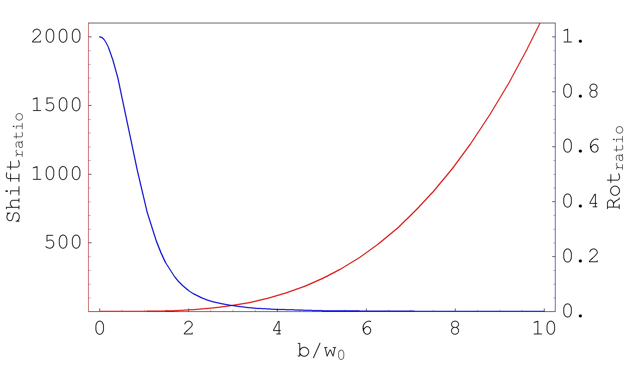
3.4.6 Gaussian beam coupling to FM and CM beams
For the application to advanced GW interferometers FP cavities it is of fundamental importance to find the best Gaussian injection beam which has the maximum coupling with the Mesa beam resonating in the Mexican hat cavities. This can be computed analytically using the above formulas. Lets take the scalar product, at the waist plane, between a gaussian field of waist and the FM beam field (3.76)
| (3.98) |
After the integration we have
| (3.99) |
Fig. 3.13 shows the power directly coupled, from a gaussian beam into a FM beam. The maximum coupling, which occurs for solution of
| (3.100) |
in agreement with erika , can be quite large, i.e for we have a power coupling of with a gaussian beam of .
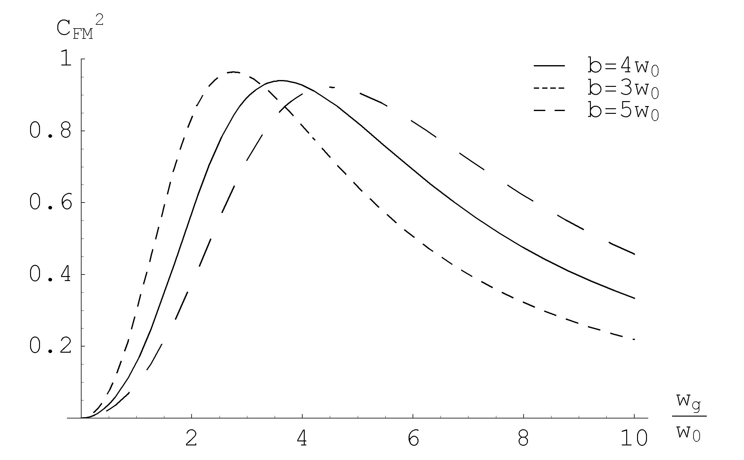
We now proceed to the same calculation for the CM beam, which seems the most promising design for advanced interferometers
| (3.101) |
Carrying out the integration we have
| (3.102) |
The maximum coupling occurs for solution of
| (3.103) |
As shown in Fig.3.14,for the proposed design , a power coupling of occurs with .
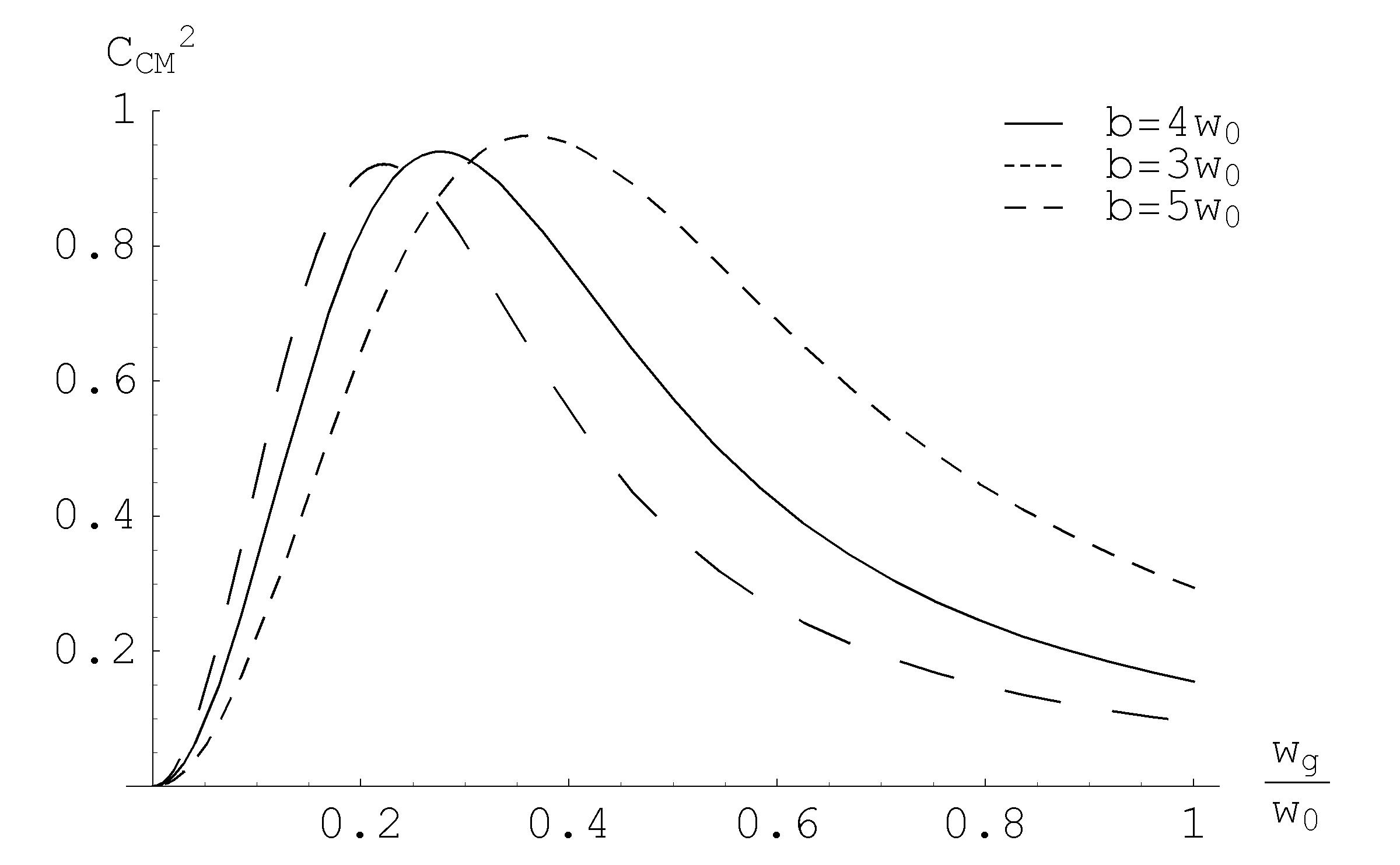
Therefore, direct coupling of a gaussian beam with a mesa beam can be very efficient in both configurations.
3.5 Application of the duality relation to real problems
Spherical cavities are not optimal in terms of their thermal noise: (the two types of) mesa beams, whose intensity profiles are flatter given the same loss specification, turn out to provide much lower thermal noises. For these beams, the larger the parameter , the lower the thermal noises, but the higher the diffraction loss. The loss specification of Advanced LIGO corresponds to which is the case we study in Fig. 3.4. While having the same diffraction losses and thermal noises, dual configurations do differ significantly in a very important aspect: their eigenspectra are different. Thus, any problem using modal analysis of optical cavities will reveal these differences.
It has been recently pointed out sidles that the force induced by radiation pressure, when the end mirrors of an optical resonator are misaligned in tilt, can induce a positive feedback and further increase the tilt. This effect is obviously power dependent and increases with power. In the case of anti-symmetric tilt, the coupling between the laser radiation pressure and the misalignment makes the mirrors tilt further, while in the symmetric case the torque induced by the light beam impinging on the mirrors, counteracts the tilt. Calculations show that the antisymmetric tilt is much more critical, and is therefore advantageous of reducing the effects of the antisymmetric case even at the expense of worsening the symmetric case. Although control systems are designed to keep the mirrors aligned, they have limited authority, and minimized coupling between radiation pressure and cavity misalignment is desirable, when there is positive feedback. Quantitative assessments of the problem sidles (that depends on the geometry of the resonator) have shown that optical cavities with almost flat mirrors are more prone to the antisymmetric instability with respect to almost concentric cavities (where the comparison is done between geometrical configurations that correspond to the same transverse distribution of the fundamental mode on the reflective surface of the mirrors). In Fig. 3.15 there is a geometrical explanation of this phenomenon for the spherical mirror case.

Because of this issue, the current baseline design for Advanced LIGO has been changed from nearly flat to nearly concentric AdLIGORefDes .
It is important to evaluate the radiation pressure problem for the case of mesa beams. We will use our proved duality-relation to show that, in the quasi-concentric Mexican-Hat configuration, the cavity is less prone to become unstable and therefore easier to control poster . For general, non-spherical cavities, a perturbative approach must be used to calculate the tilt instability. The torque due to radiation pressure is expressed in terms of numerically found eigenvalues and intensity profiles of the cavities’s spatial eigenmodes. Using the numerical work done for the mesa beam in the nearly flat configuration, and using the mapping of eigenvalues and eigenmodes between the nearly flat and nearly concentric cavities (to obtain the estimation of the tilt instability for nearly concentric Mexican-Hat cavities without having to solve the eigenvalue problem again) we proved that, for the antisymmetric case, the nearly concentric MH configuration is much more stable than the nearly flat MH one, and even slightly more stable than the corresponding nearly concentric spherical configuration proposed for Advanced LIGO. The same results were obtained by Savov and Viatchanin Savov-Vyat using a similar modal analysis.
3.5.1 Perturbation theory for finite size mirrors
Since the propagation between finite mirrors is described by non-unitary operator, Eq.(3.43) we can’t apply the standard perturbation theory, based on a set of power-orthogonal modes. We derived a rigorous procedure for perturbative analysis in the finite mirror case, which converges to the standard approach in the limit of infinite mirrors. With this method we can apply a perturbative approach even in those cases where the diffraction losses are large and the optical modes are greatly affected by the mirror finiteness. The drawback is that, since the modes of an open resonator are the eigenmodes of a non-unitary operator, it cannot be rigorously guaranteed that they form a complete set. We simply make the assumption that these modes can be used as a basis set and check this assumption numerically by examining the convergence of the series expansion.
In general we have that for a non hermitian operators, a biorthogonality relation holds between the eigenfunctions of the operator , the transposed operator and the hermitian adjoint operator . , and will have separate and different sets of eigensolutions fulfilling these relations
but no simple relationship between eigenfunctions and for non-hermitian operator ()
Instead of being power-orthogonal () the eigenfunctions of will be biorthogonal to the eigenfunctions of the corresponding transpose (or hermitian adjoint) operator
In the special case of simple optical cavities the kernel (3.43) is always symmetric in and this implies 161616This is not true for more general types of resonator like ring resonator. These cases are discusses in siegman . .
In the following we will use a compact formalism for hermitian scalar product and usual integration and we will assume that the eigenmodes are power-normalized even if not power-orthogonal.
| (3.104) | |||
| (3.105) | |||
| (3.106) |
To keep light notation we will indicate simply with the set of integers which characterize the eigenvalues and eigenvectors of our problem (e.g. for unperturbed aligned cylindrically symmetric cavity).
Assume that we solved the eigenvalues problem for the kernel , which corresponds to the unperturbed cavity
| (3.107) |
and we want to study the effect of a small perturbation (e.g. small mirror tilting) so that the resulting full kernel can be written as
| (3.108) |
We’d like to solve this problem using a perturbation series and to keep track of powers of the perturbation we will make the substitution where is assumed to be a small parameter in which we are making the series expansion of our eigenvalues and eigenvectors.
| (3.109) | |||
| (3.110) | |||
| (3.111) |
where the superscript are the zeroth, first, and second order terms in the series and is a normalization factor.
Using these equations we can write
| (3.112) |
For this equation to hold as we vary , it must hold for each power of . Looking at the first three terms
| (3.113) | |||
The zero order term is the solution of the unperturbed problem and so there is no new information there, but we can extract the first and second order correction to eigenvalues and eigenvectors from the other two terms using the orthonormality of the functions . Multiplying these equations by or and integrating over the free coordinates we have after straightforward calculations
Where the denominators take care of the normalization properties for the eigenfunctions. The normalization factor played no role in the solutions to the eigenvalues equation since that equation is independent of normalization. We can easily derive the normalization factor for the first order corrected eigenfunction .
| (3.116) | |||
The correction is of order and can’t be neglected at this level of approximation.
These results are nearly formally the same as in quantum mechanics but we have to keep in mind the different meaning of our notations (the expression of the normalization constant is completely different due to the fact that we don’t have power-orthogonal functions).
3.5.2 Evaluating tilt instability
The case of antisymmetric mirror tilt, as indicated above, is the possible source of laser-power driven instability.
The mechanical torque exerted by the misaligned fundamental mode on the mirror is given by
| (3.117) |
For a symmetric spherical mirror cavity, the torque can be computed, at the leading order, using very simple ray-beam physics. The pure geometric contribution is given by where is the displacement of the optical axis (see Fig. 3.15 given by . This very quick result is completely in agreement with sidles ; Savov-Vyat .
In the special case of mirror’s antisymmetrical tilt by a small angle we have that the full kernel describing the propagation from one mirror’s surface to the other is
| (3.118) |
If we can write this kernel as
| (3.119) |
and we can identify
| (3.120) |
We now calculate the lowest order correction to the fundamental eigenmode and eigenvalue.
so the first order correction to the lowest eigenvalue is zero and before calculating the second order correction let us calculate the first order coupling coefficient
Remembering the form of the unperturbed eigenfunctions we have that the possible non zero terms involve only (the radial index may vary) and the result is
| (3.121) |
Since the same kind of integral enters in the definition of we can easily see that the sum over reduces to just one contribution
| (3.122) |
We now calculate the first order corrections in the case (lowest radial eigenfunctions) so that the eigenfunctions entering in the integrations are of the form
From Eq. 3.117 and the above results we have the dominant contribution is given by
| (3.123) |
This can be written as explicit function of the eigenvalues and radial eigenfunctions
| (3.124) |
From our numerical calculation for the solution of the eigenvalues equation using the algorithm explained in Sec. 3.2 follows these results: Fig. 3.16 shows the intensity profiles of the lowest order modes of a symmetric Mexican hat symmetric cavity (both FM and CM). Tab. 3.2 shows an example of eigenvalue calculation for a Mexican hat mirrors cavity like Ad-LIGO proposal ()
| FMH | ||
|---|---|---|
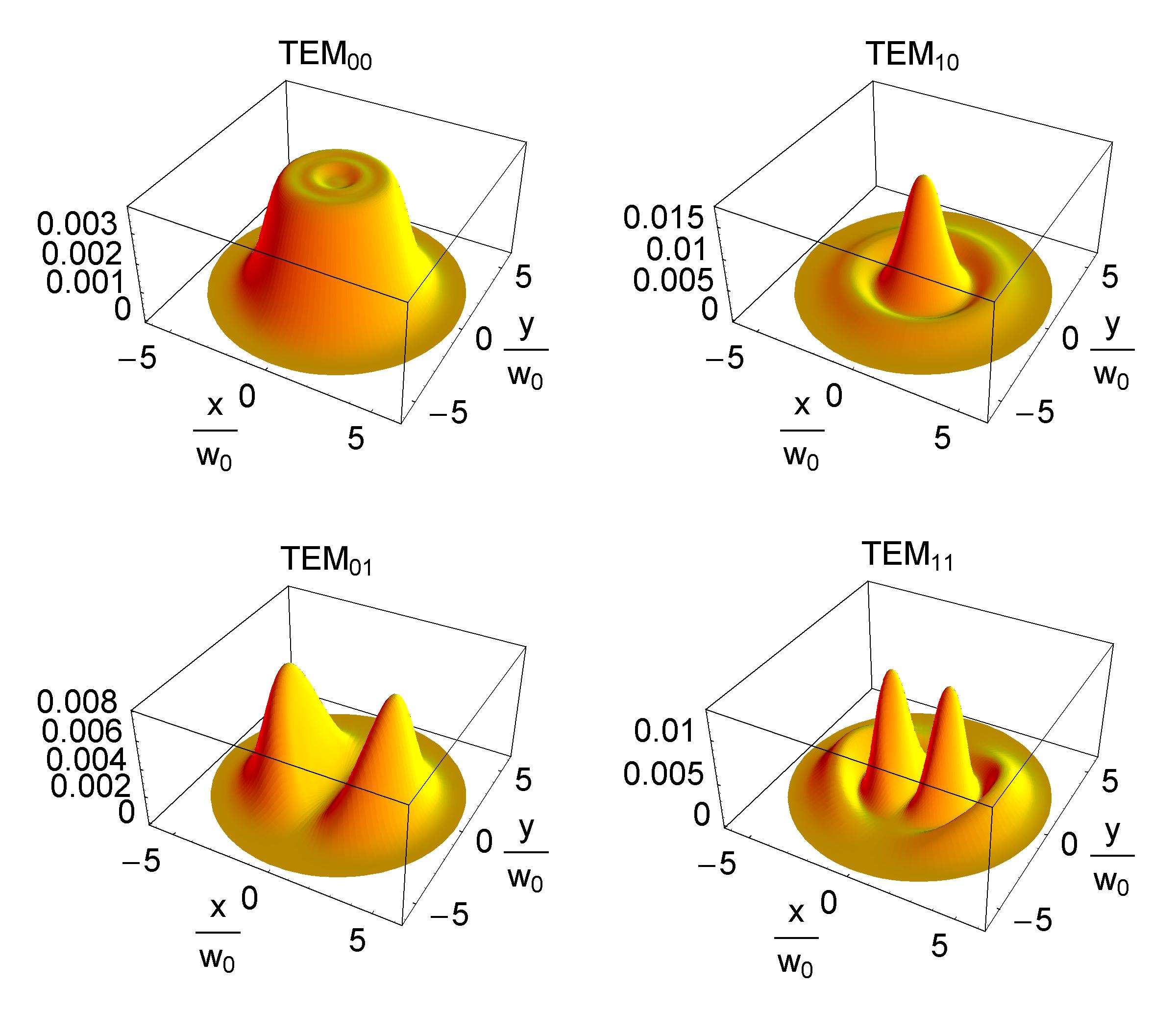
Using our equivalence relation we can immediately write the eigenvalues and eigenvectors in the nearly concentric case
| (3.125) |
and the numerical calculations for the overlapping integrals are performed using the eigenfunctions of the FMH configuration (Fig 3.16).
We calculate the ratio between the coupling coefficients of the nearly-flat and nearly-concentric configurations
which means that the MH-concentric configuration is about 250 times less sensitive to antisymmetrical-tilt induced torque than the MH-flat configuration.
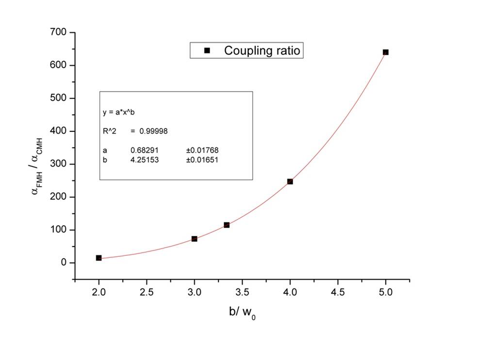
In Fig. 3.17 we investigate the sensitivity of different mesa beam design with respect to the baseline Advanced LIGO configuration.
As we will see in Sec. 4.8, increasing the mesa beam radius has the advantage of reducing the mirror thermal noise. In particular the configuration with should be the optimal choice for Ad-LIGO in terms of thermal noise, and this correspond to a factor of between the torques in the FM and CM configuration.
3.6 Mexican Hat cavity experiment
This work is a collaboration with M. Tarallo , J. Miller, R. DeSalvo, E. D’Ambrosio, P. Willems, B. Simoni, J.M. Mackowski and A. Remillieux, colleagues at University of Pisa, the LIGO Laboratory at Caltech and LMA (Laboratoire des Matériaux Avancés) in Lyon. The main motivation of this project SPIEmio ; mesabeam is to demonstrate the feasibility of building a Fabry-Perot cavity with Mexican Hat mirrors, which can support a Mesa beam.
The aim of this experiment is to explore the main properties of a single optical cavity before any eventual use in a second generation gravitational-wave interferometer. In particular, we are interested in studying the experimental mesa field achievable with realistically imperfect mirrors and how its behavior differs from that of a gaussian field with respect to perturbations such as cavity misalignments. Other groups have demonstrated mesa beam cavities using deformable mirrors beyersdorf ; derosa , but such mirrors are not obviously usable in low-noise gravitational wave interferometry.
The MH mirror production technique sets the main constraint to the prototype geometry.
The production of the Mexican hat mirror has been undertaken in the Laboratoire des Matériaux Avancés in Lyone (LMA). They use a three steps deposition process over a micro-polished flat substrate: the general shape coating, the corrective coating and the multi-layer coating. In the first step a “rough” Mexican hat shape is deposited with a precision of about nm using a profiled mask and rotating the substrate to generate the cylindrical symmetry. The mask, calculated from the thickness profile of the ideal Mexican hat, is placed between the sputtered flow of silica and the rotating substrate.
The second step is a more precise correction of the “general shape” previously obtained. This method controls the deposited profile with a precision of about nm Peak-to-Valley (PV). Nevertheless, it is not possible to coat more than nm with this technique, because it would require a deposition time which is too long. The measurement of the achieved mirror shape after the first deposition is performed using an interferometric technique. The comparison between the achieved and the desired mirror shape generates a data file which is used to move the robot arm that positions the mirror in front of the corrective silica beam. The main limitations of the corrective technique come from the measurement of the wavefront, the precision of the robot arm movement and the size and resolution of the corrective beam. The maximum achievable slope is nm/mm, thus setting a limit on the smallest feasible Mexican hat mirror. Finally, a high reflectivity multi-layer coating is deposited on the corrected substrate. The slope of the Mexican Hat mirror profile 3.4(b) sets the radius of the smallest feasible mesa beam made using our technique to about mm.
Our smallest practical mirror size sets our cavity length to meters. We further reduced the physical length of the structure to m by building a half-symmetric cavity (a single MH mirror paired with a flat mirror at what would be the midpoint of a full length cavity) and then to m by folding. In this way it was possible to build a rigid suspended cavity.
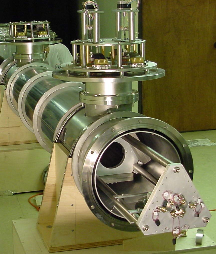
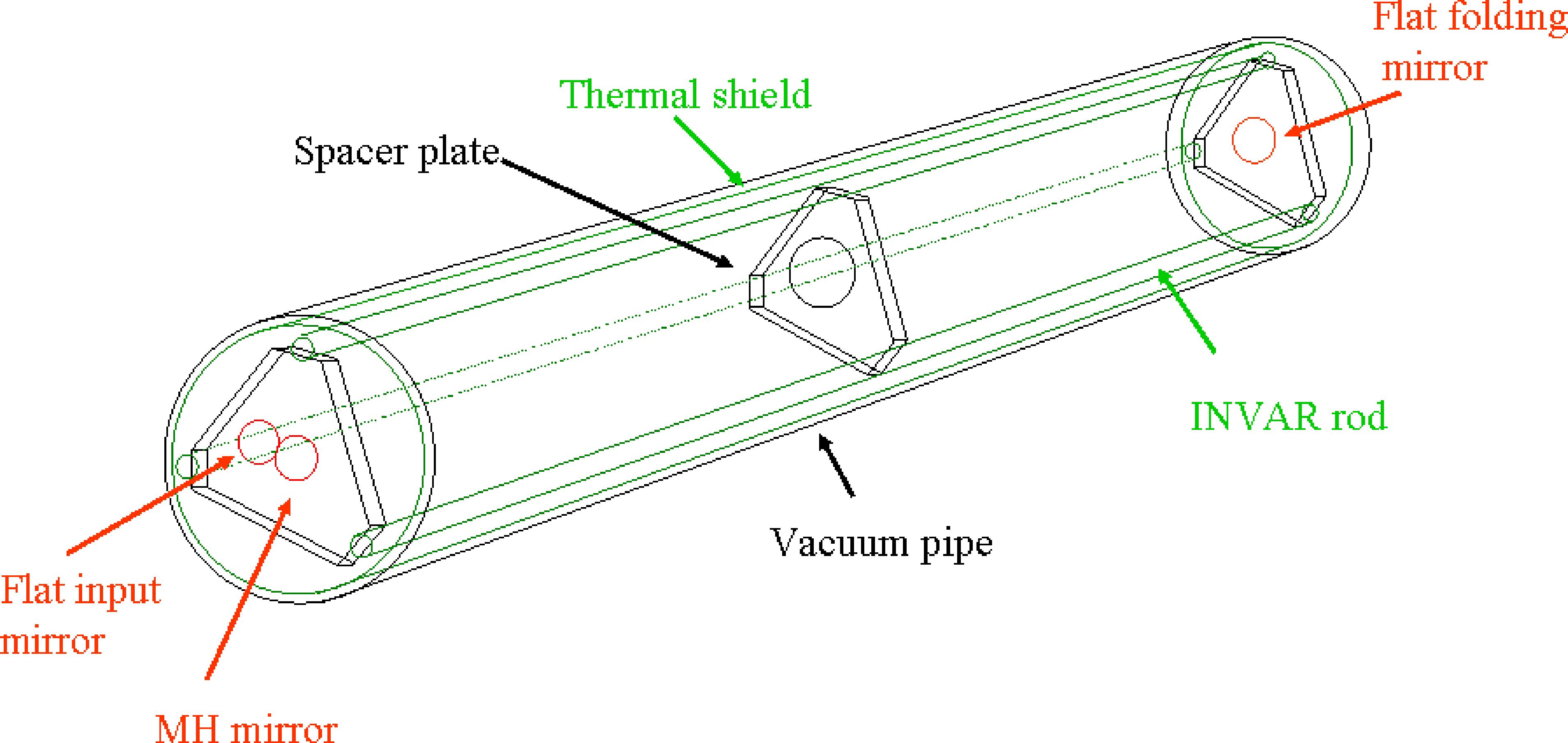
Fig. 3.18(a) shows the suspended cavity. Three Invar rods fix the cavity length to = 23.657 m = 7.32 m, with a folding mirror at one end of the structure and the input and end mirrors on the other end. Five triangular spacers maintain structural rigidity, with the outer two spacers bolted at the ends of the structure and containing the mirror mounts. The cavity is suspended by two pairs of maraging steel wires from GAS (Geometric-Anti-Spring) cella blades, providing both horizontal and vertical isolation. The whole is suspended in an aluminum chamber for thermal stability and protection from air currents; this chamber is not evacuated.
The test MH mirror was designed using the waist size of the minimal gaussian with as a reference length, so that the resulting mesa beam had a radius mm. We required that our test mirror have similar diffraction loss around its aperture as an Advanced LIGO test mass; in order to have 1 ppm diffraction loss the mirror radius was set to mm.
Due to the technical difficulties of the MH figure deposition on the flat substrate, the MH mirror had non-negligible figure error [see Fig. 3.19], mostly in the central bump where the height is just nm. In particular, the figure error reaches a maximum of nm at the edge of the central bump.
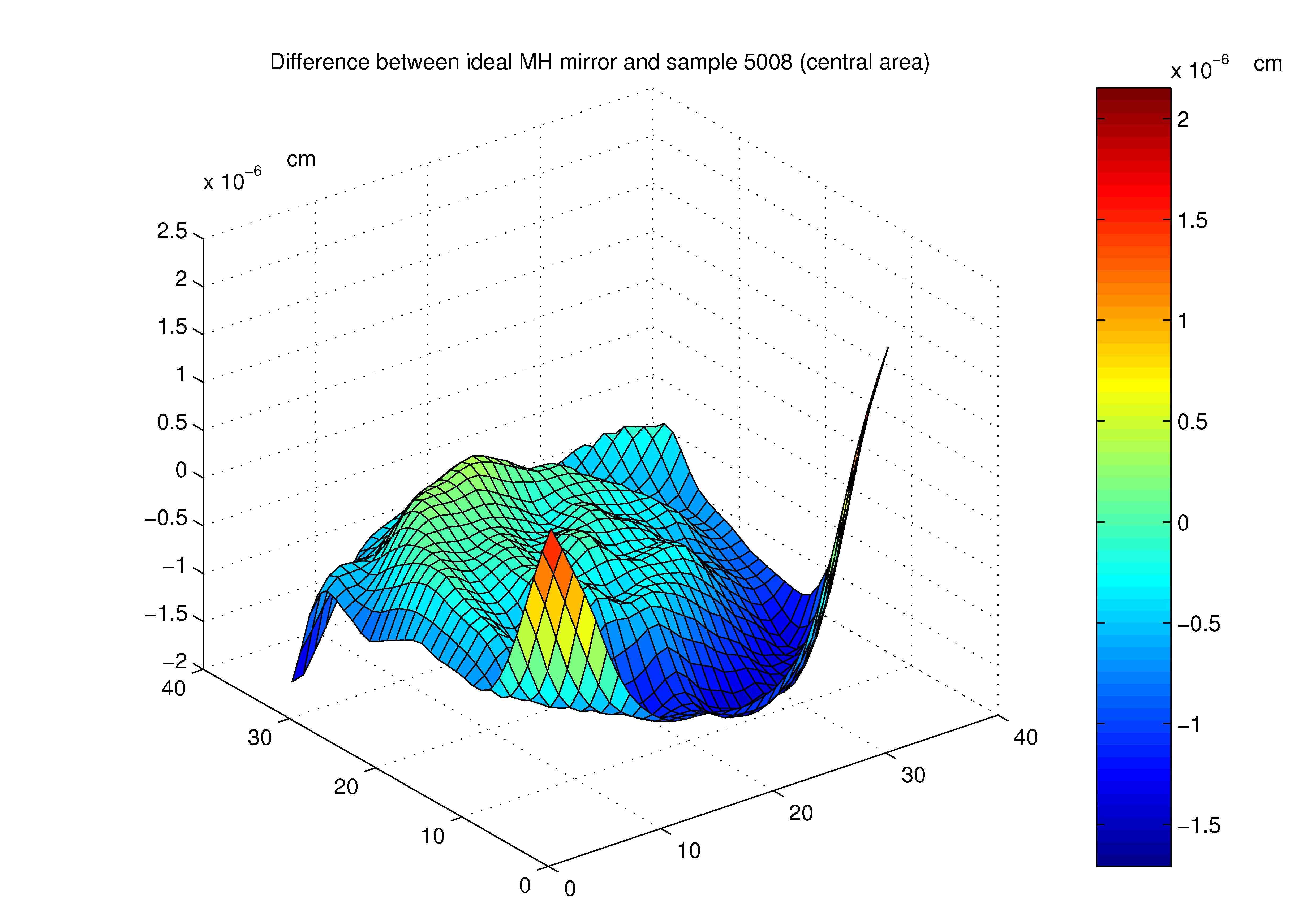
Further details on the experimental set-up and the development of the project are given in the MS thesis of Simoni SimoniTesi and Tarallo TaralloTesi .
3.6.1 Comparison between experiment and simulations
In order to simulate our FP cavity we used a dedicated version of the FFT implementation described in Sec. 3.3. Its aim is to investigate the impact of misalignments and mode matching with the input Gaussian beam driving the FP cavity and to study the cavity behavior with imperfect mirrors using real mirror maps for setting requirements and tolerance for Mexican hat mirror manufacture and control constraints. From the mirror’s maps we can make theoretical prediction of the sensitivity of this new type of optical cavity to mirror imperfections and alignment. Since the geometry of the Mexican hat mirror of this FP cavity is completely different from the standard spherical mirrors supporting Gaussian beams, the effects of misalignment for mesa beams are more important. In the Mexican hat case, the change in the surface of the mirror due to orientation has a more general effect: not only does the cavity have a new optical axis but the phase profile sensed by the beam is quite different. For spherical mirrors this is not the case since an incident beam experiences the same curvature at all points on the mirror surface.
We have mounted the sample , one of the three made in the LMA laboratory. As shown in Fig. 3.19 it presents significant deviations from the design mirror shape. In particular, there is an evident slope in the central part of the mirror, which manifests itself by modifying the expected beam shape, as shown in the FFT simulation of Fig. 3.20(a). We used the map of this sample mirror in our simulation program to characterize the properties of the resonating light. Our simulations have shown that the resulting beam shape could fit the expected flat top behavior: by slightly changing ( rad) the alignment of the mirror we can partially correct for this intrinsic tilt. The best beam we could obtain with this imperfect mirror is shown in Fig. 3.20(b)(assuming perfect flat input and folding mirrors). The ripples in the central area are inevitable due to the roughness of the mirror surface (limited by the accuracy of the corrective coating deposition) and set a limitation of about PV on the flatness of the power distribution on the top of the beam.
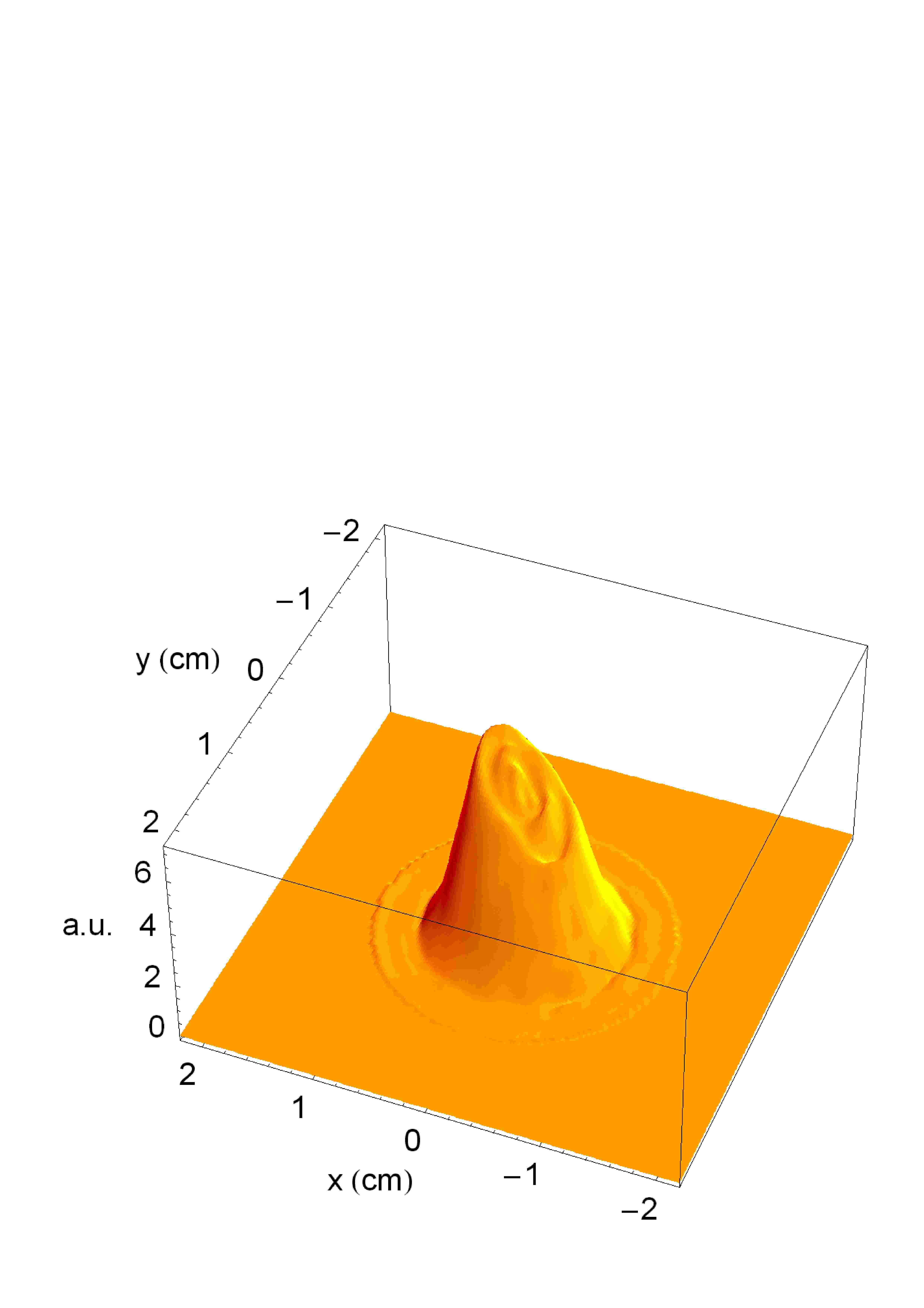
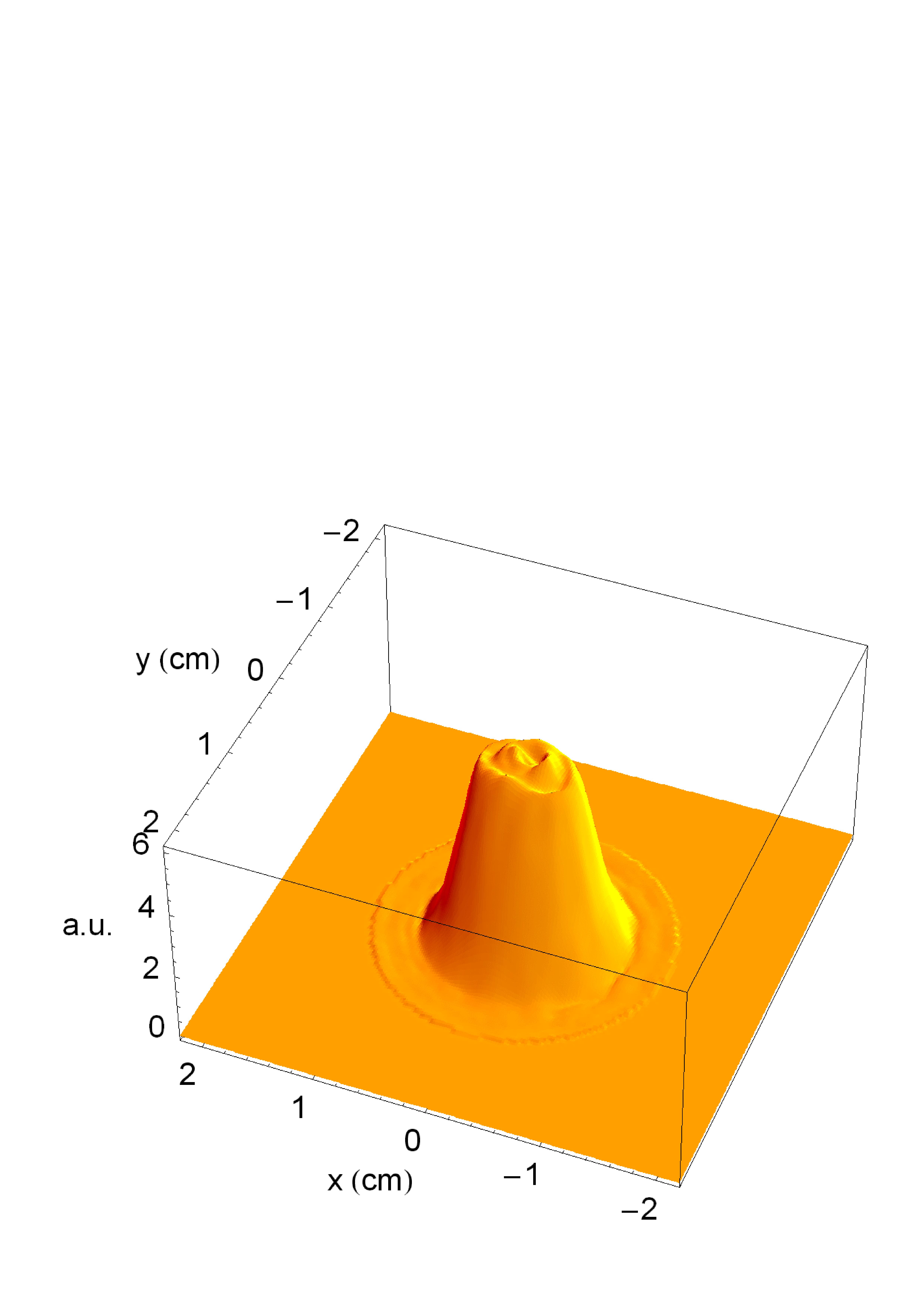
3.6.1.1 Alignment and intrinsic defect correction
The greatest experimental difficulty was found in obtaining a sufficiently precise alignment to achieve a flat top power distribution in the cavity. In a cavity made with spherical mirrors, a tilted mirror presents the same spherical profile to the opposite mirror, but shifted sideways, and the cavity simply resonates the same transverse mode spectrum centered upon a shifted optical axis. In contrast, the MH mirror has a non-spherical shape, and any misalignment destroys the cylindrical symmetry of the cavity. In such a situation the resonant beam senses a mirror with a suboptimal profile and the cavity mode will thus have a radically different intensity distribution and phase front. When our cavity was in such a misaligned state, higher order and distorted modes were found easily. We were able to reproduce these patterns with our simulation program by changing the alignment of the MH mirror and/or shifting the input Gaussian beam as shown in Sec. of TaralloTesi .
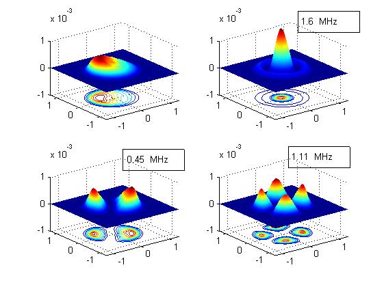
Fig. 3.21 shows the simulated cavity spectrum when a tilt of rad is applied to the MH mirror. The higher order modes are less effected by the MH mirror tilt with respect to the fundamental mode; this is traduced in the experiment in a greater difficulty in aligning the mirrors to obtain a fundamental flat mode. On the other side higher order (misaligned) modes are obtained very easily.
3.6.1.2 Cavity modes and spectral distribution
The extreme sensitivity to misalignment proved to be caused by our nominally flat folding and input mirrors, which had surface deviations of order nm from flatness before we fixed aluminium compensating/strengthening rings to them. Having reduced the flat mirrors’ flexure, it was possible to lock the cavity to a stable fundamental mode with nearly uniform distribution. In fact, taking into account the residual warping of the flat mirrors and MH mirror imperfections, this mesa beam is consistent with the best achievable using our current prototype MH mirror [see Fig. 3.22]. Figure 3.23 shows four beam profiles. Two are experimental data, smoothed with a mm ( pixels) gaussian kernel to clean them of digitization noise and dust diffraction rings. The other two are profiles simulated using our FFT code. The simulated profiles represent the leakage field at the output bench ( meters from the input mirror) achieved applying the ideal corrective tilt at the MH mirror.
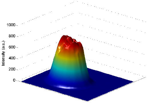
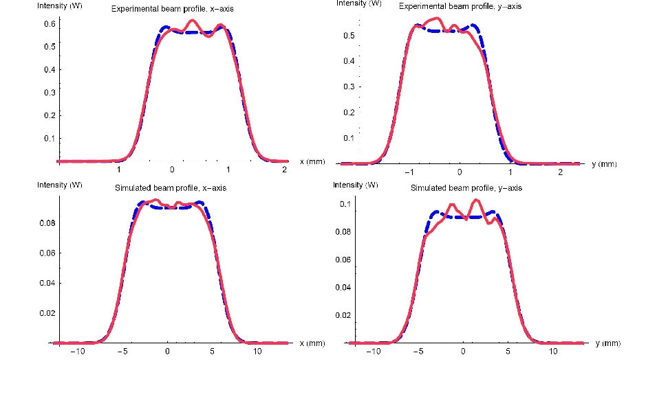
Analyzing the profile in Fig. 3.23, the normalized absolute power in the simulated profile not fitted by the mesa TEM00 is . By comparison, the normalized absolute power in the experimental profile not fitted by the mesa TEM00 is , after the normalization of the power on the CCD, with a peak to valley deviation from the flat profile of about . These numbers suggest that the resulting mesa beam is very close to the experimental limit due to the imperfect MH test mirror.
In Fig. 3.24 we show some higher-order transverse mesa beam modes observed. These modes are superficially quite similar to the Laguerre-gaussian modes for a spherical mirror Fabry-Perot cavity. However, in the precise power distribution there are differences as shown in Fig. 3.25. The experimental data is in good agreement with the expected mesa TEM10 profile. As for the fundamental mode, there is some asymmetry due to the mirror imperfections.
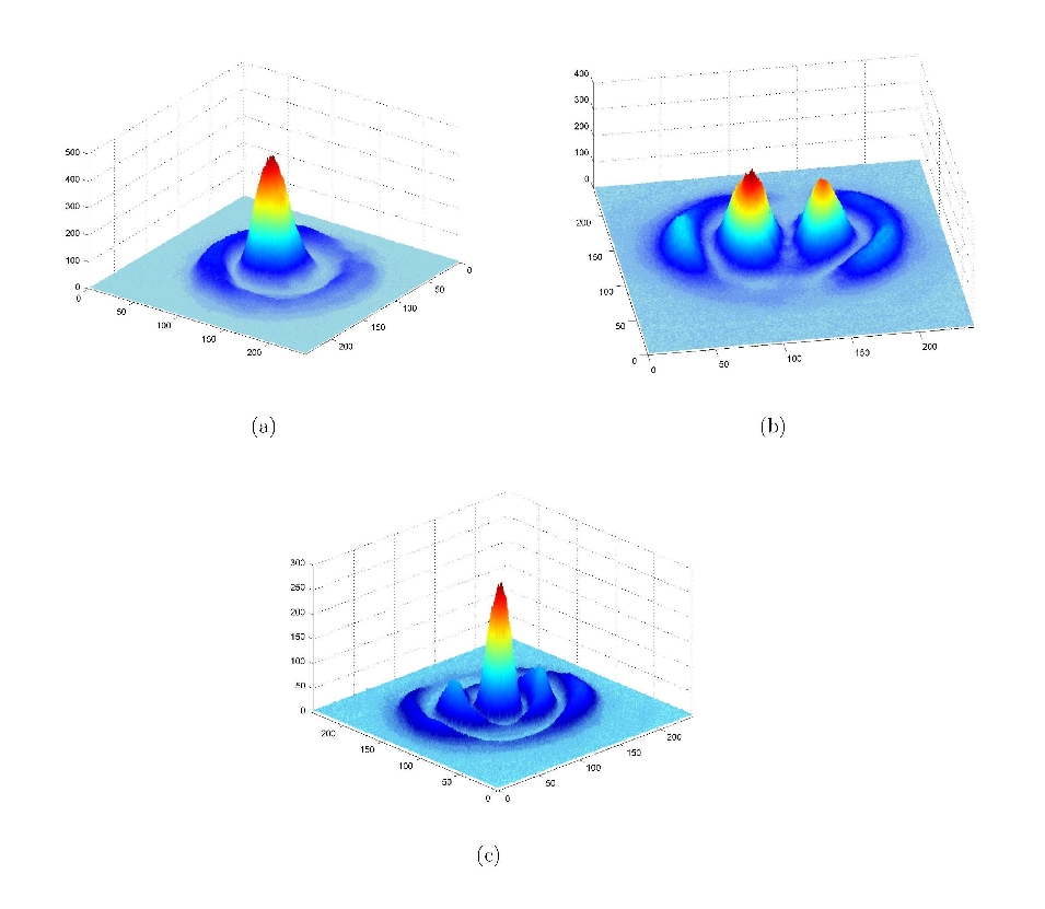
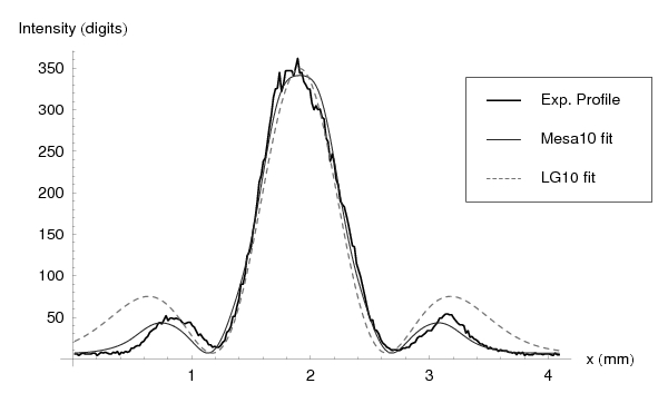
A simple study has been done to compare the numerical predictions for our resonator and cavity length sweeps. Results are shown in Tab. 3.3.The second column is calculated assuming perfect MH and flat Input mirrors. Although the estimate has large uncertainty ( MHz due to frequency spacing and systematic effects) we can conclude that the numerical predictions are well respected.
| Peak | (MHz) | TEMpl (expected) | |
|---|---|---|---|
| 1 | 0 | 00 | 0 |
| 2 | 0.4413 0.2 | 01 | 0.4141 |
| 3 | 1.198 0.2 | 02 | 1.0945 |
| 4 | 1.574 0.2 | 10 | 1.6542 |
| 5 | 2.144 0.2 | 03 | 1.9905 |
| 6 | 2.900 0.2 | 11 | 2.8789 |
| 7 | 4.161 0.2 | 12 | 4.1754 |
| 8 | 4.414 0.2 | 20 | 4.4050 |
| 9 | 5.549 0.2 | 13 | 5.5523 |
| 10 | 5.801 0.2 | 21 | 6.0031 |
The mirrors imperfections and the quite large deformations of the Input mirror cause a deformation in the mode shapes and some shifting in the resonances spectrum. The simulation shown in Fig. 3.26 is performed using our algorithm described in Sec. 3.2.3. The cylindrical symmetry is broken by the mirror’s imperfection/deformations and the power distribution over the lobes of the higher order modes is no more symmetric (as experimentally observed)
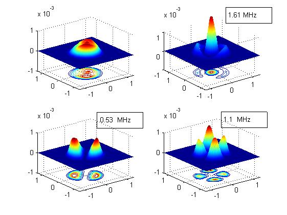
3.6.1.3 Tilt sensitivity
Since the mesa beams are intended for use in actual interferometers it is important to study their ease of control. Some theoretical and experimental investigations have been carried out in this area reducing ; oshaug ; erika ; beyersdorf . The alignment tolerances for a mesa beam arm cavity are expected to be times more stringent than those of the gaussian arm cavity in an advanced gravitational wave detector.
In our m cavity (just as in a long baseline GWID), extremely small tilts create significant modification of the mesa beam profile.
The tilt precision of the optical lever is estimated to be rad.
Figure 3.27 shows the good agreement between our recorded profiles (thin lines) and FFT simulated data (thick lines). Note that these FFT simulated profiles were constructed using a two-mirror cavity (as opposed to the real three-mirror cavity).
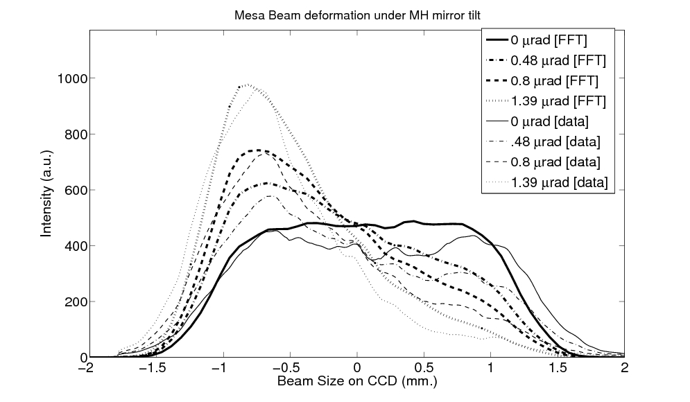
Chapter 4 Thermal noise in view of GW sensitivity improvements
4.1 Introduction
Thermal noise is one of fundamental noise sources in precision measurement, such as gravitational experiments Saulson:1990jc . It is expected that the sensitivity of the next generation interferometric gravitational wave detectors (see Fig. 1.3) will be limited by the thermal noise of its optical components (i.e. mirrors substrate and high-reflective dielectric coatings). Therefore, it is important to study the thermal noise in view of sensitivity improvement. In this chapter, the fundamental theorem and the estimation method of the thermal noise are introduced. Moreover, the evaluation of the thermal noise of the interferometric gravitational wave detectors are discussed. We will analyze two different method for thermal noise reduction: the first based on beam shaping whereas the second on coating optimization. In this thesis we calculate for the first time the coating noise reduction using mesa beam instead of standard Gaussian beam and we show that the mesa beam is a good candidate111There are currently different studies on other beam shapes Galdi ; vinetLG (and so other mirror shapes) to minimize the mirror thermal noise. We will comment briefly on this aspect later. for application in advanced GW interferometers.
4.2 Fluctuation Dissipation Theorem
The fluctuation-dissipation theorem (FDT) is one of the most important theorems of non-equilibrium statistical mechanics. The FDT predicts the relationship between the spectrum of the thermal noise and the dissipation of linear222The linearity states that the amplitude of the response is proportional to the amplitude of the driving force. dissipative333A system is considered dissipative if, under an external solicitation, it absorbs energy through irreversible processes. systems. Since the thermal fluctuations and the dissipation are governed by the same interaction between a system and the heat bath, there must be a relation between both phenomena. This theorem was established by Callen et al. PhysRev.83.34 . In their fundamental work, they established a generally valid connection between the response function and the associated equilibrium quantum fluctuations, i.e., the quantum fluctuation-dissipation theorem. Another key development must be credited to Lars Onsager: via his regression hypothesis, he linked the relaxation of an observable in the presence of weak external perturbations to the decay of correlations between associated microscopic variables Onsager1 ; Onsager2 . This all culminated in the relations commonly known as the Green–Kubo relations Callen-Green ; Kubo . This notion of “linear response” related to the fluctuation properties of the corresponding variables constitutes the (response) fluctuation-dissipation theorem.
For a macroscopic system, the fluctuation-dissipation theorem describes the behavior of any generalized coordinate of any system that is weakly coupled to a thermalized bath with many degrees of freedom. The interaction between the system and externals is represented by a fluctuating generalized force, . The information of the dissipation of this system is included in the response of to . This response is derived from the equation of motion of the system.
The information of the dissipation of the system is embedded in a generalized impedance function , and the FDT establishes a relation between the spectral density of the spontaneous fluctuations exhibited by the system in equilibrium and this generalized admittance (the inverse of the impedance) of the system. The impedance is defined as
| (4.1) |
where and are the Fourier components of the generalized force and velocity, respectively. If the system were completely conservative, then the impedance would be perfectly imaginary. The bath prevents the system from being conservative: energy can be fed back and forth between the generalized coordinate and the bath’s many degrees of freedom. This energy coupling changes the impedance from pure imaginary to complex, and correspondingly, the resulting motions of feed energy into the bath and vice versa. The FDT states that the spectral density (power spectrum) of the thermal fluctuation for the quantity is
| (4.2) |
and that the spectral density of the generalized force 444This is also known as generalized Nyquist noise formula is given by
| (4.3) |
The fluctuation dissipation theorem is derived from the assumption that the response of a system in thermodynamic equilibrium to a small external perturbation is the same as its response to a spontaneous fluctuation. Therefore it seems natural to look for a direct relation between the fluctuation properties of the thermodynamic system and its linear response properties to an external perturbation, which is coupled exactly to the generalized coordinate we are interested in. Levin Levin proposed a direct and very powerful method for the application of the FDT and derived a formula which requires no specific information about the dissipation mechanism, apart from the fact that it should be dissipation of mechanical energy and that the localization and the amount of dissipation are known. As a consequence, the Levin formula can be used to study a broad range of thermal noise induced fluctuations associated with all specific dissipations. We imagine to apply to the system an external oscillatory force that derives the generalized momentum conjugate to but does not derive the other generalized momenta of the system. In order to introduce this force into this equation of the motion, the new term,
| (4.4) |
is added to the Hamiltonian of the system. From the definition of the generalized impedance we have that and the average dissipated power within the system as a function of the driving frequency is given by
| (4.5) |
| (4.6) |
where we have done the substitution since the same reasoning can be repeated for any driving frequency (in the range coupled to the bath) and the spectral density has the claimed form anywhere in this range. This formula is particulary useful because for many systems, the calculation of the dissipated energy is simpler than that of the real part of the generalized admittance function.
4.2.1 FDT: superposition principle
In many practical situations it is necessary to evaluate the behavior of system in which the generalized coordinate we are looking at is a superposition of other generalized coordinates of the system. This can be the case of the surface of a mirror as seen by a laser beam profile, since the displacement sensed by the laser beam can be expressed as a spatially weighted superposition of the internal modes of the mirror interacting with the beam itself. Since the FDT is based on the linear response theory, it is obvious that for any linear combination of generalized coordinates we can repeat the reasonings of the previous section and obtain analogous formulas for the FDT. Lets define a new coordinate as a weighted superposition of certain system’s generalized coordinates
| (4.7) |
The generalized force that drives the momentum conjugated to is introduced in the Hamiltonian of the system, trough the following interaction term
| (4.8) |
and the generalized admittance of the system becomes
| (4.9) |
where and are the Fourier components of the generalized force and of the velocity of the new generalized coordinate respectively. The spectral density of the thermal fluctuation for the coordinate is given by
| (4.10) |
4.3 Mirror thermal noise
The standard thermal noise is the phase noise caused by random motions of the reflecting faces of mirrors in a GW interferometer. A reflecting face can move either because it is displaced by its suspension systems or because it undergoes internal stresses. At finite temperatures both effects are possible. We address here the internal stresses. Consider a massive body at temperature . If the atoms constituting the body are excited and have random motions around their equilibrium position. The fact that they are strongly coupled to neighboring atoms makes possible propagation of elastic waves of various types, reflecting on the faces and the onset of stationary waves. One can show that, for a finite body (like for instance a cylinder of silica) there is a discrete infinity of such stationary waves, each corresponding to a particular elastic normal mode. At thermal equilibrium, the state of the body can be represented by a linear superposition of all the modes, with random relative phases, and, due to the energy equipartition theorem, the same energy ( is the Boltzmann constant). The motion of atoms near a limiting surface of the body will slightly modify its shape, and if we consider the reflecting face of a mirror, a surface distortion is cause of phase change in the reflected beam; in other words, of a noise. Estimation of the resulting spectral density of phase noise in the probe beam is the internal thermal noise problem in massive mirrors.
Modal expansion is a traditional method to calculate thermal noise. Although now superseded by the Levin approach, we find it useful to first discuss the general concept of this method and then discuss its application to the mirror. In a frequency domain, the equation of motion of a one-dimensional harmonic oscillator is written as
| (4.11) |
where m is the mass of the oscillator, and is the angular resonant frequency of the oscillator. We introduced the mechanical loss as the loss angle , and is called the complex spring constant. For a mechanical system with a spring constant, we describe the dissipation as the imaginary part of a complex spring constant. In the standard theory of inelasticity, Hooke s law is extended to represent the internal friction process, leading to a description of the dissipation of energy in the oscillator in terms of its complex stiffness spring. As a matter of fact, Eq. (4.11) has merely phenomenological relevance to express the experimental appearance of a lag angle between the stress and the strain and the behavior with respect to the frequency. The mechanical impedance of the system is given by
| (4.12) |
and the application of the FDT (4.2) allows the calculation of the spectral density of the thermal fluctuations of the oscillator’s position
| (4.13) |
Before giving a short overview of the modal expansion approach to the calculation of the FDT, we have to summarize and fix the notation for the elastic theory of continuum media which will be used in the following Sections.
4.4 Basic elasticity theory
We label the position of a point (a tiny bit of solid) in an unstressed body, relative to some convenient origin, by its position vector . Let a force be applied so the body deforms and the point moves from to ; we call the point’s displacement vector. The strain tensor is defined as a second-rank tensor field given by the covariant derivative of the displacement vector which can be written in arbitrary system of coordinates using index notation and the symbol ‘;’ for covariant derivative
| (4.14) |
In a Cartesian coordinate system the components of the gradient are always just partial derivatives.
The strain tensor is a general, second-rank tensor. Therefore, its irreducible tensorial parts are its trace , which is called the deformed body’s expansion; its symmetric, trace-free part , which is called the body’s shear; and its antisymmetric part , which is called the body’s rotation:
The strain tensor can be reconstructed from these irreducible tensorial parts in the following manner
| (4.15) |
Since the third term represent a rigid rotation which does not deform the solid and we are interested in the deformation itself, it is useful to rewrite the strain tensor as
| (4.16) |
The first part is a symmetric tensor and represents elongation, compression, and shear. In many textbooks this part alone is called strain tensor. The displacement due to rotation will be not considered in the following since it is not related to the deformations of the elastic body.
The forces acting within an elastic solid are measured by a second rank tensor, the stress tensor. Consider two small, contiguous regions in a solid. If we take a small element of oriented area in the contact surface with its positive sense pointing from the first region toward the second, then the first region exerts a force (not necessarily normal to the surface) on the second through this area. The force the second region exerts on the first (through the area ) will, by Newton’s third law, be equal and opposite to that force. The force and the area of contact are both vectors and there is a linear relationship between them. The two vectors therefore will be related by a second rank tensor, the stress tensor :
| (4.17) |
and the elastic force per unit volume acting on a solid can be expressed as the divergence of the stress tensor
| (4.18) |
The diagonal terms of the stress tensor define the normal stresses in the coordinate system in which is expressed. The off-diagonal terms define the shear stresses. Normal stresses act parallel to the unit vector orthogonal to the surface while shear stresses act perpendicular to it. The conservation of angular momentum requires that the stress tensor be symmetric. Consequently, there are only 6 independent stress components to be determined.
To understand the relationship between stress and strain in elastic media, we must generalize Hooke s law for continuous, linear, elastic media.
The most general linear equation relating two second rank tensors will involve a fourth rank tensor known as the elastic modulus tensor or elastic stiffness tensor, . In tensor notation we have
| (4.19) |
The inverse relation defines the fourth rank compliance tensor
| (4.20) |
Now, a general fourth rank tensor in three dimensions has independent components. However there are several symmetries that we can exploit. As the stress tensor is symmetric, and only the symmetric part of the strain tensor creates stress, is symmetric in its first pair of indices and also in its second pair. Moreover, from the expansion of the elastic internal energy in terms of components of strain, it can be shown that the elastic tensor must be symmetric under the interchange of the first two indices with the second ones. There are therefore independent components in .
Many substances, notably crystals, exhibit additional symmetries and this can reduce the number of independent components considerably. The simplest, and in fact most common, case arises when the medium is isotropic. In other words, there are no preferred directions in the material. This occurs when the solid is polycrystalline or amorphous and completely disordered on a scale large compared with the atomic spacing, but small compared with the solid’s inhomogeneity scale.
If a body is isotropic, then its elastic properties must be describable by scalars. Now, the stress tensor , being symmetric, must have just two irreducible tensorial parts, a scalar part and a trace-free symmetric part; and the parts of the strain that can produce this behavior are the scalar expansion and the trace-free, symmetric shear , but not the rotation. The only linear, coordinate-independent relationship between these tensorial quantities involving solely scalars is
| (4.21) |
Here is called the bulk modulus and the shear modulus, and the factor is included for purely historical reasons. Sometimes it is convenient to introduce the Lamé coefficients which are related to by the relation
| (4.22) |
and write the elastic tensor in a generic coordinate system as
| (4.23) |
and the relation between stress and strain tensor as
| (4.24) |
In terms of the Young modulus and the Poisson coefficient the linear elasticity relation (4.19) for an isotropic and homogeneous body can be written as
| (4.25) |
If one has coordinate components, found from generalized coordinate tensor analysis, for some quantity, such as stress or strain, one needs to be able to translate those into the values measured in the experiment. The method for doing this is reviewed in Appendix A.1. The measured value for a given vector component, unlike the coordinate component, is unique within a given reference frame. In differential geometry (tensor analysis), that measured value is called the “physical component”(App. A.1). It is important to recognize that physical components do not transform as true tensor components and one can not simply use physical components in tensor analysis as if they were. Typically, one starts with physical components as input to a problem. These are converted to coordinate components, and the appropriate tensor analysis carried out to get an answer in terms of coordinate components. One then converts these coordinate components into physical components as a last step, in order to compare with values measured with instruments in the real world. Since we will deal with only orthogonal coordinate (Cartesian and Cylindrical) we can restrict our discussion to orthogonal coordinate systems in which the metric tensor is diagonal and
| (4.26) |
The physical components of a tensor are given by the components of the tensor with respect to unit basis vectors. In the following sections we will deal with orthonormal cylindrical basis and the components denoted by are referred to this basis. More details about the relation between physical components and tensorial components is given in App. A.1.
4.4.1 Thermal noise with mode expansion
When the thermal noise of the internal modes of a mirror in interferometric gravitational wave detectors is calculated, the mirror is treated as a elastic cylinder. Cylindrical coordinates are employed with the origin at the center of the mirror and the -axis along the cylindrical axis. The observable coordinate, , which is the surface displacement averaged by the beam power distribution, is expressed as
| (4.27) |
where is the component of the displacement vector , and the weighting function is the normalized distribution of the beam power over the mirror surface. The external generalized force that drives the momentum conjugated to is introduced in the equation of motion without dissipation for the elastic body in the following form
| (4.28) |
where is the density and we have used the equation of motion of a linear and homogeneous elastic body (Eq. (A.14) in App. A.2). We can look for a solution of (4.28) in the form of a normal modes expansion, that is, we write the following superposition of basis functions
| (4.29) |
The basis functions, , are the solution of the eigenvalue problem, for the free elastic body, written as
| (4.30) |
where and correspond to the angular resonant frequency and the displacement of the n-th resonant mode of the system, respectively.
The function, in Eq.(4.29), represents the time development of the n-th mode. The equation of motion of is derived substituting the equation Eq. (4.29) for in Eq. (4.28) and using the orthogonality property of the complete set of functions . The result is written in the form
| (4.31) |
where the parameter , called effective mass of the n-th mode, is defined by the normalization choice for the functions
| (4.32) |
where is the component of . Therefore, the time evolution of the n-th mode is the same as that of a harmonic oscillator of mass and angular resonant frequency with an external force acting on it. Using Eq. (4.29) and Eq. (4.4.1)in Eq. (4.27) it follows
| (4.33) |
showing that the observable coordinate can be simply described as a superposition of the motions of the harmonic oscillators . Up to now we neglected dissipation in the system. To describe dissipation, the loss angles,, are introduced in the frequency domain equation for the normal modes evolution. Equation (4.31) is rewritten as
| (4.34) |
| (4.35) |
| (4.36) |
Therefore the thermal motion of the system is expressed as the sum of the contributions given by the harmonic oscillators of the normal-mode expansion. Equation (4.36) allows to calculate the thermal noise from the angular resonant frequency , the effective mass and the loss angle of each mode. The angular resonant frequency and the displacement of the mode are obtained from the eigenvector problem, Eq. (4.30) . The effective mass is calculated from the found and equation (4.4.1). The loss angle is derived from the experiments but its measurement in a wide frequency range is commonly difficult; thus, it is usual to estimate it from the Q-value on the resonant frequencies for different modes, according to the following relation:
| (4.37) |
There are two methods to solve the eigenvalue problem. The first one is the method proposed by Hutchinson Hutch . This is a very accurate semi-analytical algorithm to simulate resonances of an isotropic elastic cylinder. The second method is the finite element method which is a numerical method. The thermal noise can be calculated using (4.36), where the summation has to be done over a number of modes that assures a good convergence of the series. Using the mode expansion formalism described above, the mirror thermal noise of interferometric gravitational waves detector has been calculated by Gillespie–Raab Gillespie , Bondu–Vinet Bondu:1995ur under the assumption of homogeneously distributed loss inside the mirror bulk.
Recently, a problem of the modal expansion method was clarified in yamamoto . The introduction of the mechanical loss after the system is divided into basis functions, is not equivalent to the solution that is directly obtained from the equation of motion with the loss included since the beginning. The modal expansion fails, especially when the loss is inhomogeneously distributed in the system, , because of a coupling between the internal modes. The LIGO mirrors, composed of several parts, mirror substrate, coating, magnet, each with its own loss mechanism, correspond to this case.
4.5 Thermal noise: direct calculation
At present the technique recognized to be the most appropriate to calculate the thermal noise is the “direct” method. It has the advantage that leaves aside the modal decomposition. There are many different ways of implementing this computation, Levin s approach Levin , Nakagawa s approach Nakagawa and Numata’s numerical dynamic approach Numata . In the following we limit the discussion to Levin’s method explained in Sec. 4.2, since this is the approach used in this thesis work.
Consider the surface of the mirror invested by the laser beam which has a profile given by the weighting function . The read-out variable will be the generalized coordinate expressed as a continuous combination of system coordinates in the form of Eq. (4.27). Using the FDT, Eq. (4.10), the calculus of the thermal noise reduces to the calculus of the real part of the admittance. Levin’s method consist in the calculation of from the average mechanical energy dissipated by a particular driving force. Suppose to apply on the mirror surface an oscillatory continuous force that mimics the profile of the laser beam:
| (4.38) |
This force corresponds to a generalized force
| (4.39) |
4.6 Mirror thermal noise contributions
Mirror thermal noise (in the bulk and in the coating), can be divided into:
-
•
Brownian thermal noise,
-
•
thermoelastic noise,
-
•
thermorefractive noise.
In this thesis, we will focus our attention on these kinds of mirror thermal noises and we will show the possible sensitivity improvements in using a mesa beam instead of a standard Gaussian beam.
4.6.1 Brownian thermal noise
Internal friction in solids was identified by Kimball and Lovell PhysRev.30.948 , who described it as a phase shift between stress and strain. Brownian thermal noise due to mirrors, can be interpreted as a fluctuation of the mirror surface position coming from the mirror modes thermal excitation or, using the FDT, as fluctuations induced by a structural damping. In the real lattice, impurities, dislocations and imperfections play the role of dissipation sources in the phonon dynamics. Irreversible processes can also be attributed to relaxation mechanism in asymmetric potential-well models Two-level ; Diss-asi . Thermal noise due to homogeneously distributed damping processes, such as Brownian bulk noise in GW detector mirrors, can be estimated using complex valued elastic coefficients whose imaginary part is related to the dissipation mechanism. For example, the structural damping can be parameterized by a complex material s Young modulus, were the imaginary part is related to the energy dissipation of the system
| (4.40) |
Measurements Freq-silica have shown that is dependent on the frequency , but its dependence is sufficiently slow that it can be neglected in the frequency region of interest. To calculate the power spectral density associated to Brownian bulk motions, Levin expressed in Eq. (4.6) as
| (4.41) |
where is the loss angle of the substrate, denotes the time average over the period of the oscillatory pressure previously defined and is the elastic energy stored in the substrate of the test mass. This energy is derived by using elasticity theory, and will depend on which monitoring beam profile you use as well as the mirror s dimensions. Levin supposed that the mirror is an infinite half-space and that the elastic deformation follows quasistatically the oscillatory pressure (a reasonable hypothesis because the first resonance mode of the mirror is far higher than the region of interest). In the case when the beam has a gaussian profile and the mirror is approximated by a semi infinite half-space, the displacement spectral density will be Levin
| (4.42) |
The calculation was also made by Bondu et al. Bondu:1998sm , and reviewed by Liu and Thorne LT in the case of a finite size mirror.
The correction to the noise spectral density is an infinite series of Bessel function with coefficients depending on the material properties and on mirror and beam-spot size dimensions. If compared with the result in the approximation of infinite mirror mass, this calculation gives a correction to the thermal noise that, e.g. in the case of the new Advanced LIGO mirrors, starts to be greater than for beam spot sizes greater than cm.
Considering that there is the project to use flat beams, this correction becomes crucial in estimating the Brownian thermal noise correctly.
4.6.2 Thermoelastic noise
Thermoelastic noise is intended as a noise that comes from the coupling of thermal fluctuations with displacement fluctuations thanks to a non-null coefficient of thermal expansion. The oscillating squeeze and stretch of the substrate material causes an oscillating, inhomogeneous temperature distribution: heat flows down the temperature gradient in such a way that it converts oscillation energy into additional heat.
The inhomogeneity of the deformations causes the temperature perturbation to be inhomogeneous, and that inhomogeneity produces a heat flux . Whenever an amount of heat flows from a region of temperature to one of slightly lower temperature , there is an increase of entropy and the resulting rate of entropy increase per unit volume is
| (4.43) |
This entropy increase entails a creation of new thermal energy at a rate per unit volume . Since, for our thought experiment with temporally oscillating applied stress, this new thermal energy must come from the oscillating elastic energy, the rate of dissipation of elastic energy must be
| (4.44) |
To calculate this noise for the mirror it is necessary to solve a system of two coupled equations, the first one is the elasto-dynamic equation for the displacement including a stress term coming from the temperature inhomogeneity, and the second one is the thermal conductivity equation for the temperature perturbation including an heat-source term coming from the non uniform expansion. As the time required for sound to travel across the mirror is usually smaller than the oscillatory period, it is often used a quasistatic approximation in the equation of elasticity for a field of deformation
| (4.45) |
The thermal conductivity equation for the temperature inhomogeneity
| (4.46) |
where and are Young modulus, Poisson ratio, the coefficient of linear thermal expansion, the thermal conductivity and the specific heat per unit volume at constant volume of the mirror. Braginsky et al. Braginsky:1999rp solved the problem using the fluctuation-dissipation theorem in the form (4.10), approximating the mirror with an infinite half-space and considering that the oscillatory period is far higher with respect the typical time scale of the diffusive heat flow. This is the so called adiabatic limit in which the second term on the left hand side of (4.46) is neglected. In this approximation, is simply proportional to the elastic expansion .
Liu and Thorne LT solved the same problem with the same approximations applying the FDT in Levin s form, Eq. (4.6), and using (4.44). They found that the displacement power spectrum for half infinite mirror is
| (4.47) |
They also made the calculations for a finite cylindrical test mass finding the correction factor w.r.t. the infinite test mass solution. Depending on the mirror/beam geometry and the mirror’s material this correction can be several .
Cerdonio et al. Cerdonio extended the previous analysis releasing the assumption of the adiabatic limit, i.e. performing the analysis that is valid also at low temperatures and/or small beam spot size. Equation (4.47) has to be multiplied by a correction factor, which depend on the ratio between the beam radius and the thermal diffusivity length (that is frequency dependent).
4.7 Coating thermal noise
It has been pointed out Levin that it is critically important how the losses are distributed inside the test masses. Losses far from the beam spot contribute less to the total thermal noise, whereas losses near the spot, for example in the dielectric coating directly reflecting the beam, contribute more.
The coatings on the mirrors play the crucial role in reflecting the laser used for position sensing off of the test mass. They must be highly reflective and able to handle high optical power, to reduce shot noise, and have low levels of intrinsic noise. Primary among intrinsic noise are thermally driven motions of the coating face and the optical path length.
To obtain the required high reflectivity, multi-layers, dielectric coatings are used. Such coatings consists of alternating ion-beam deposited layers of optical thickness equal to (at m) of two dielectric materials with differing refractive indexes (i.e., for initial LIGO). It was found Penn-loss that the mechanical loss comes from internal dissipation of the coating materials, and it is the high index Tantalum-pentoxide that is primarily responsible for the thermal noise in first generation interferometers.
Another source of thermal noise is thermally driven fluctuations in the optical path length of the coating. This can occur from thermal fluctuations in length, i.e. thermoelastic noise BVcoat ; Fejer , or from fluctuations in the refraction index, i.e thermorefractive noise Braginsky:2000wc . These two mechanisms are driven by the same thermal fluctuations, therefore will add coherently. This collective noise source is referred to as thermo-optic noise. The level of thermo-optic noise in next generation gravitational-wave interferometers depends on the thermal, elastic, and optic properties of the coating materials, primarily on and . Values in literature Fejer ; BVcoat for ion beam deposited coatings indicate that thermo-optic noise could contribute to Advanced LIGO sensitivity and that the high index coating material may be the primary problem and lots of effort by the optics research groups is dedicated to measure these parameters.
4.7.0.1 Brownian coating thermal noise
Coating thermal noise due to internal losses is expected to be the dominant contribution to the thermal noise for mirrors with a coating on a fused silica substrate. Nakagawa et al. Nakagawa calculated the dissipation induced by an inhomogeneous loss distribution on a half-infinite mirror due to the fact that loss angle in the bulk material is different from loss angle in the coating but neglecting the differences in the elastic properties of the substrate and the coating
| (4.48) |
Harry et al. HarryCQG , using Levin s method, generalized this result for a non isotropic coating loss, assuming that the loss angle associated with energy stored in strains parallel to the plane of the coating, is different from the loss angle associated with the energy stored in strains perpendicular to the surface. For a thin coating, provided that , and , they found
| (4.49) |
Equation (4.7.0.1) is valid provided that the coating loss occurs in the coating materials themselves and not for rubbing in the bulk/coating or layer/layer and this has been experimentally investigated by Penn et al. Penn-loss ; Penn-loss2 .
4.7.0.2 Coating thermoelastic noise
Temperature fluctuations (that couple with displacement thanks to can be originated either by intrinsic thermodynamical fluctuation, or by laser-photon absorption. We will briefly describe the first mechanism and refer to Rao Rao for the description of the latter one since that is a negligible effect in LIGO and Ad-LIGO mirrors.
The diffusive heat characteristic length of the substrate and coating (of the order of mm) is far larger than the coating thickness (a few m). Because diffusive heat flow in the longitudinal direction is not negligible, heat flow in the direction normal to the coating cannot be treated adiabatically. The problem was extensively treated by Braginsky and Vyatchanin BVcoat and by Fejer et al. Fejer in the case of Gaussian beam. In the frequency band , where is the thermal diffusion time across the coating ( kHz for multi-layer coating), coating thermoelastic noise can be estimated by the equation
| (4.50) |
where is a dimensionless combination of material constants that vanishes when the film and substrate are identical
| (4.51) |
4.7.0.3 Coating thermorefractive noise
The thermo-refractive noise is generated by temperature fluctuations that couple with phase fluctuations of the reflected laser beam (and therefore with measured displacement), thanks to the non-vanishing coefficient , where is the refractive index. Considering the frequency range (that is typical for the ground interferometer) around Hz and an half infinite mirror with a Gaussian beam, Braginsky et al. Braginsky:2000wc calculated the equivalent displacement noise spectral density
| (4.52) |
where for a multi-layer coating which consists of alternating sequences of quarter-wavelength dielectric layers having refractive indices and 555This formula has been revisited many times during the last few years. Originally was proposed in this form in Braginsky:2000wc ; subsequently was modified in BVcoat , and recently an independent analysis Castaldi confirmed the original formula..
4.8 Thermal noise: Gaussian VS mesa beam
Coating thermal noise (4.7.0.1) due to internal losses is expected to be the dominant contribution to the thermal noise for mirrors with a coating on a fused silica substrate, whereas the thermoelastic noise of the substrate is the dominant contribution for sapphire mirrors at room temperature. The local surface fluctuations produced by thermal noise are averaged by the intensity distribution of the laser beam spot over the mirror surface. Reading the entire mirror surface with uniform sensitivity would minimize the thermal noise. The standard design of interferometers uses light beams with a Gaussian distribution of power, which are eigenfunctions of cavities with spherical mirrors, a well-developed and understood technology. Table 4.1 summarizes the geometrical dependence of each kind of mirror thermal noise on the Gaussian beam radius for half infinite test mass.
| Thermal noise | |
|---|---|
| Substrate Brownian | |
| Substrate Thermo-elastic | |
| Coating (all kinds) |
The larger is the beam radius, the better is the averaging of the fluctuations and thus lower will be the noise. However the beam size is constrained by the allowable diffraction losses requirements, which cannot exceed a few ppm. Taking into account the diffraction loss constraints, a Gaussian beam, effectively averages out the thermal fluctuations only over a few percent of the mirror surface. A significant reduction in all kinds of mirror s thermal noises can be achieved by using modified optics that reshape the beam from a conventional Gaussian profile into the “mesa-beam” profile described in Sec. 3.4. A large-radius, flat-topped beam with steeply dropping edges (necessary to satisfy the diffraction loss constraint) will lead to a better sampling of the fluctuating surface, lower noise in the determination of the mirror surface position and better sensitivity for GW detectors. The calculation of substrate thermo-elastic noise reduction using Mesa beam has been done in oshaug for sapphire test mass. More recently Vinet VinetFB calculated the substrate Brownian thermal noise reduction using Mesa beam for Virgo mirror size.
Calculation of the coating thermal noise, which is expected to be the most significant contribution to the thermal noise budget for the test masses of the next generation of GW interferometers, has never been published for non Gaussian beams and finite cylindrical test masses. In this thesis we present a comparative study of the various sources of thermal noise in different mirror and beam configurations, considering both Gaussian and Mesa beam profiles, addressing the problem of thermal noise reduction, through mirror size aspect-ratio and beam size optimization. (Some of these results have been already presented in Aspen and TNmeeting ).
4.8.1 Elastic solution for a cylindrical test mass
We used the Levin approach to the Fluctuation Dissipation Theorem (4.6) in order to calculate the power spectral density of the test mass displacement. The generalized coordinate is given by the average of the normal displacement of the test mass surface, weighted by the beam spot power distribution as introduced in Eq. (4.27). In this way the thermal noise evaluation reduces to the calculation of in accordance to the specific mechanism and localization of dissipation, i.e. Brownian or thermoelastic and substrate or coating.
The main ingredient for our calculations is the model proposed by Bondu, Hello and Vinet Bondu:1998sm and corrected by Liu and Thorne LT of the approximate solution of the elasticity equations for a cylindrical test mass subjected to the oscillatory pressure with the same spatial profile as the beam power distribution (assumed cylindrically symmetric). Consider a finite sized, cylindrical test mass with radius and thickness and with a cylindrically symmetric light spot centered on the cylinder’s circular face, which applies an oscillating pressure
| (4.53) |
where is a constant force amplitude and beam power distribution normalized over the mirror surface
| (4.54) |
The fundamental approximation underneath these calculation is the quasi-static approximation for the calculation of the displacement fields according to the oscillatory pressure which is a good approximation for oscillatory period larger than the time required for sound to travel across the test mass and far away from the resonances of the test mass.
The static stress balance equations in cylindrical coordinates derived in Appendix A.2 have to be solved together with the following boundary conditions:
-
•
No shear on the cylinder’s surfaces, i.e.
(4.55) -
•
Pressure of the beam on the front face and no normal stress at the back surface
(4.56) -
•
No radial stress on the cylindrical edge
(4.57)
The displacement vector satisfying the mentioned boundary conditions 666The boundary condition (4.57) is not fulfilled exactly, in fact, as discussed in Bondu:1998sm , the and terms in the displacement are a correction to the leading-order displacement, designed to improve the satisfaction of the boundary condition as far as calculated without these corrections can be approximated by a linear function. is given by
| (4.58) |
| (4.59) |
| (4.60) |
where and are the Bessel function of order zero and order one respectively, is the th zero of the Bessel function , and the other coefficients are
| (4.61) |
and are constants given by
| (4.62) | ||||
| (4.63) |
In the axi-symmetric case, the non-zero (physical) components of the strain tensor in cylindrical coordinates are given by
| (4.64) |
and, for an homogeneous and isotropic body, the stress components are related to the strain by the Lamé coefficients
| (4.65) |
where is the expansion.
4.8.2 Thermal noise calculations for finite size test masses
In order to manipulate these quite complicated expressions, we developed a Notebook called Thermal Noise Notebook (TNN)777Available at http://www.ligo.caltech.edu/~jagresti/ with the intent of providing a user-friendly tool which can be used by GW interferometer researchers to evaluate quickly the expected mirror thermal noise. We chose to implement the calculation using this program because of its great versatility for numerical and analytical calculation and the possibility of changing very easily all the parameters involved in the calculations, beam shape, mirror’s aspect ratio, mechanical and thermal properties of the material of the substrate and coating. We now give an overview of the calculation for the different types of thermal noise.
4.8.2.1 Substrate Brownian thermal noise
The conventional thermal noise of the substrate is given by Eq. (4.6) with the time averaged dissipation given by
| (4.66) |
where is the loss angle of the substrate, denotes the time average over the oscillatory period and is the elastic energy stored in the test mass that can be determined integrating, over the test mass volume, the elastic energy density given by
| (4.67) |
| (4.68) |
and are the component of the strain and stress tensor respectively calculated from the displacement vector using equations (4.64) and from the constitutive relations (elastic moduli tensor) for an homogeneous and isotropic material, Eq. (4.8.1). These cumbersome calculations are performed very efficiently by and will not be reported here.
4.8.2.2 Substrate thermo-elastic noise
As reported in Sec. 4.6.2, the thermo-elastic dissipation is given by
| (4.69) |
Where is the substrate thermal conductivity and is the substrate temperature perturbation induced by the elastic deformation due to the oscillatory pressure and is given by
| (4.70) |
Where is the linear thermal expansion coefficient, and are the Young modulus and Poisson ratio respectively, is the specific heat per unit volume of the substrate.
The equation (4.70) follows from the adiabatic approximation of the general thermal conductivity equation (4.46). The adiabatic approximation, already discussed in Sec. 4.6.2, consist in the following: if the time scale for diffusive heat flow is much longer than the pressure oscillating period, we can approximate the oscillations of stress, strain and temperature as adiabatic, neglecting the heat flow term in the thermal conductivity equation. Using equations (4.64) for the calculation of the expansion , substituting in (4.70) we can calculate the thermo-elastic dissipated energy in (4.44) and then the spectral density of the displacement noise given by Eq. (4.6).
4.8.2.3 Coating thermal noise
The geometry we consider for the reflective surface of the mirrors consists of a thin film of thickness on a substrate whose thermo-mechanical properties are different from those of the film. To simplify the analysis, we assumed that the multi-layer coating can be approximated as a uniform layer with appropriately averaged properties.
4.8.2.4 Coating Brownian thermal noise
In this case the averaged energy dissipated by the intrinsic losses in the coating is given by an analogous formula of (4.66)
| (4.71) |
Where is the loss angle of the coating and is the portion of elastic energy stored in the coating (in this calculation we assume an isotropic and homogeneous coating with averaged elastic coefficient: Young modulus and Poisson ratio ). In the thin film approximation , we assume that the energy stored in the coating is given by , where is the thickness of the coating and is the energy density stored at the surface, integrated over the surface, which is expressed in terms of the coating stress and strain as
| (4.72) |
In the thin film approximation, the coating is approximated as a thin layer in which the stress and strain do not vary considerably as a function of depth within the coating and we shall approximate them as being constant. Following HarryCQG , the stresses and strains in the coating can be calculated in terms of the stresses and strains at the surface of the substrate because of the boundary condition between coating and substrate: the coating must have the same tangential strains as the surface of the substrate and the coating experiences the same perpendicular pressure as the surface of the substrate. Since the only exerted force is normal to the plane we must have no shear stress on the coating, ,( is a boundary condition for the elastic problem of the substrate). The coating stress and strain can thus be calculated by the following equations
| (4.73) |
In this way we can calculate all the fields necessary for the computation of the elastic energy stored in the coating, , using the expressions already found for the substrate.
4.8.2.5 Coating thermo-elastic noise
In the thermo-elastic problem of the coating is important to note that the coating thickness, the diffusive heat transfer length and the beam radius satisfy the following relation
| (4.74) |
This relation justify the approximation of the multi-layer film as a uniform film with averaged properties and when computing the oscillating temperature distribution we can consider the temperature variation as adiabatic in the transversal direction and that only the thermal diffusion orthogonal to the surface of the mirror need to be considered. The two thermo-elastic coupled equations (4.45) and (4.46) are solved perturbatively at the first order in the linear thermal expansion coefficient . We first consider the quasi-static stress-balance equation at the zeroth order in which has been solved in the preceding section (Eqs. 4.8.2.4). Then, we solved the thermal conductivity equation Eq. (4.46) for a one-dimensional heat flow and using the zeroth order elastic fields as the source term.
| (4.75) |
where is the expansion at the mirror surface associated with the zeroth-order elastic fields calculated for the previous sections and indicates quantities evaluated in the substrate and the coating respectively. For a multi-layer coating this equation determines an averaged temperature field and the coating quantities are averaged following Fejer . If and are the thickness of the two materials composing the coating (), we have
| (4.76) |
Assuming a time dependence of the form for the oscillatory thermal and elastic fields, equations (4.75) can be cast in this form
| (4.77) |
with the boundary conditions of zero heat flux at the surfaces of the test mass and continuity of temperature and heat flux at the boundary between coating and substrate
| (4.78) |
The general solution of (4.77) is given by
| (4.79) |
The boundary conditions (4.78) determine the four arbitrary constants and the solutions for the temperature variation induced in the coating and in the substrate are
| (4.80) | ||||
| (4.81) | ||||
The dissipated power for the coating thermo-elastic noise is given by
| (4.82) |
where we are neglecting the dissipation due to the radial heat flow 888The correction is completely negligible for the coating contribution, and is around for the substrate dissipated power. and the integrals are extended over the substrate and coating volume respectively. Averaging Eq. (4.82) over the oscillatory period, and inserting the result in Eq. (4.6) we have the spectral density of displacement noise due to coating thermo-elastic fluctuations.
4.8.2.6 Coating thermo-refractive noise
Thermodynamical fluctuations of temperature in mirrors of gravitational wave antennae may be transformed into additional noise not only through thermal expansion coefficient but also through temperature dependence of refraction index. In this case we cannot use the original Levin’s method999Recently Levin proposed a variation of its original direct method, to calculate the thermo-refractive noise [arXiv:]. to calculate this noise because it is not associated with mechanical energy dissipation. Following Braginsky:2000wc , the spectral density of the equivalent displacement noise can be written as
| (4.83) |
where is the laser wavelength, is the spectral density of temperature fluctuation in the coating and for a multi-layer quarter wavelength optical coating is given by
| (4.84) |
The spectral density of the temperature fluctuation can be calculated using the Langevin approach explained in Braginsky:2000wc . For semi infinite mirror and for cylindrically symmetric beam profile , it is easy to derive the following equation
| (4.85) |
where is the Hankel transform of the normalized power distribution over the mirror surface.
In this section we want to give just an estimation of the coating thermo-refractive noise reduction using a flat beam instead of a Gaussian beam and for this purpose we will approximate the real mesa beam as a perfect Flat Top beam
| (4.86) |
For Gaussian and Flat Top beam the Hankel transform can be analytically performed but the integral in (4.8.2.6) must be numerically evaluated (unless other approximations are accepted, as done in REF). For this comparison we chose a value of which correspond to the “standard” radius of the integration disc for Mesa Beam and compare this ideally flat beam with the Advanced LIGO Gaussian baseline design . The displacement noise is reduced by a factor in the case of a Flat Top beam.
| (4.87) |
4.8.3 Results and discussion
This is a scheme of the calculations performed with TNN for the analysis of the expected mirror thermal noise in Ad-LIGO interferometer:
-
•
we fixed the mirror mass at , constrained by the Advanced LIGO suspension system design AdLIGORefDes .
-
•
We fixed the diffraction loss constraint at for both the Gaussian and the Mesa beam, calculating the diffraction losses with the so called clipping approximation; in this approximation the losses are computed by the amount of light that falls outside the mirror and the beam profile is assumed to retain its shape even though the diffraction from the edge of the mirror.
-
•
We changed the mirror radius from to (with per step) and at the same time we increased the Gaussian beam radius and the Mesa beam integration disc radius to satisfy the constraint for diffraction losses. The corresponding values are shown in Fig. 4.1. The thickness of the mirror is reduced correspondingly to satisfy the total mass constraint. In this way all the geometric parameters in the problem are functions of the mirror radius .
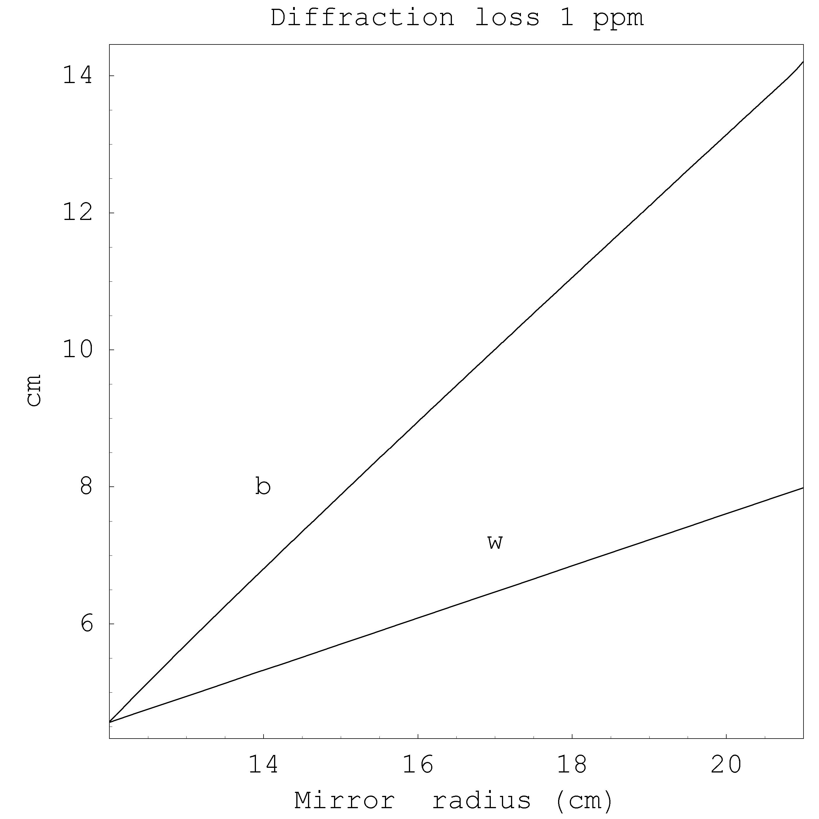
4.8.3.1 Fused silica substrate
Figures 4.2(a), 4.3(a), 4.4(a), 4.5(a) show the displacement noise of all the analyzed thermal noise contributions, for Gaussian and Mesa beam in the case of Fused Silica substrate. The dominant noise, the coating Brownian thermal noise, undergoes a reduction of a factor for a mirror radius of cm. The substrate thermal noise is reduced by a factor , whereas the coating thermo-elastic and the substrate thermo-elastic are reduced by factor and respectively.
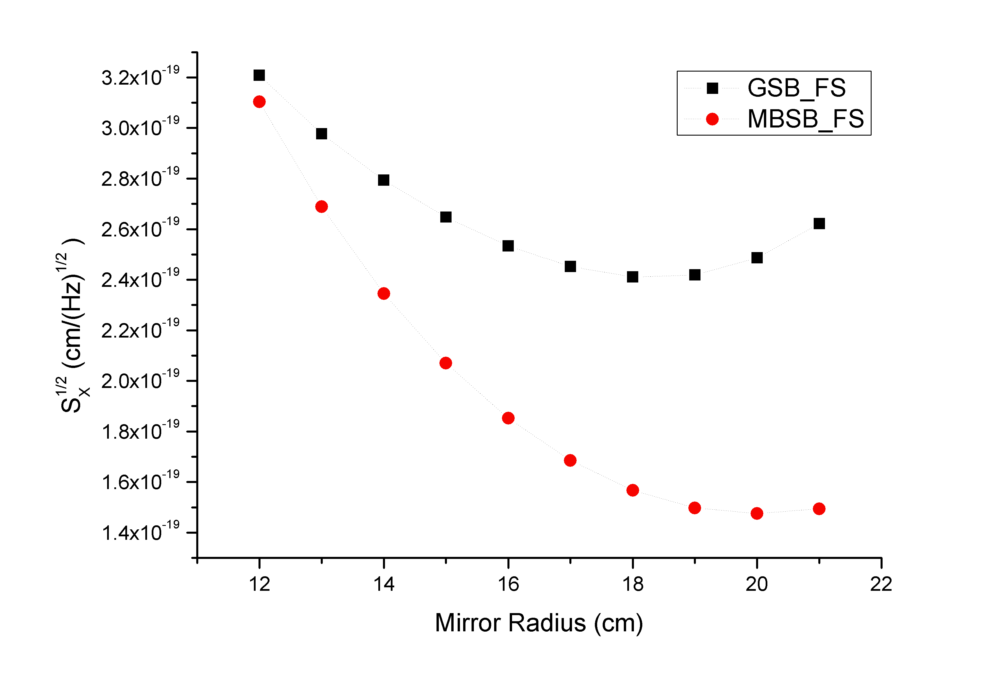
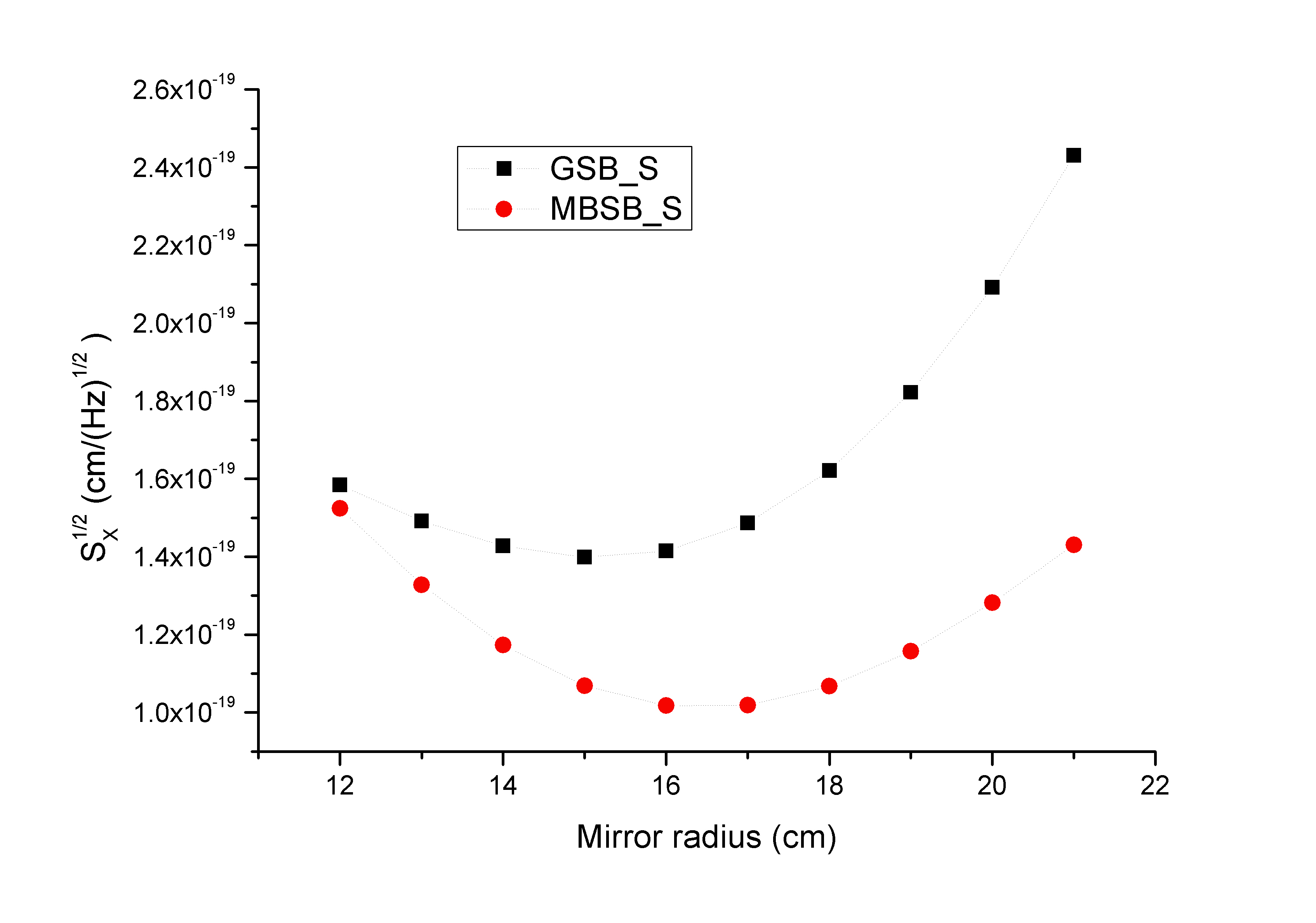
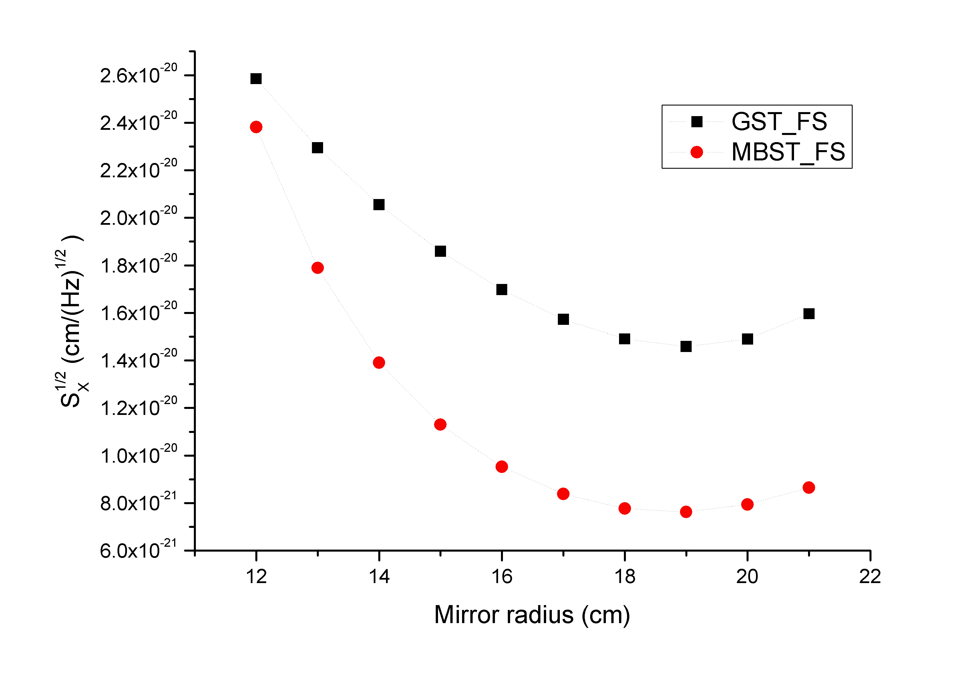
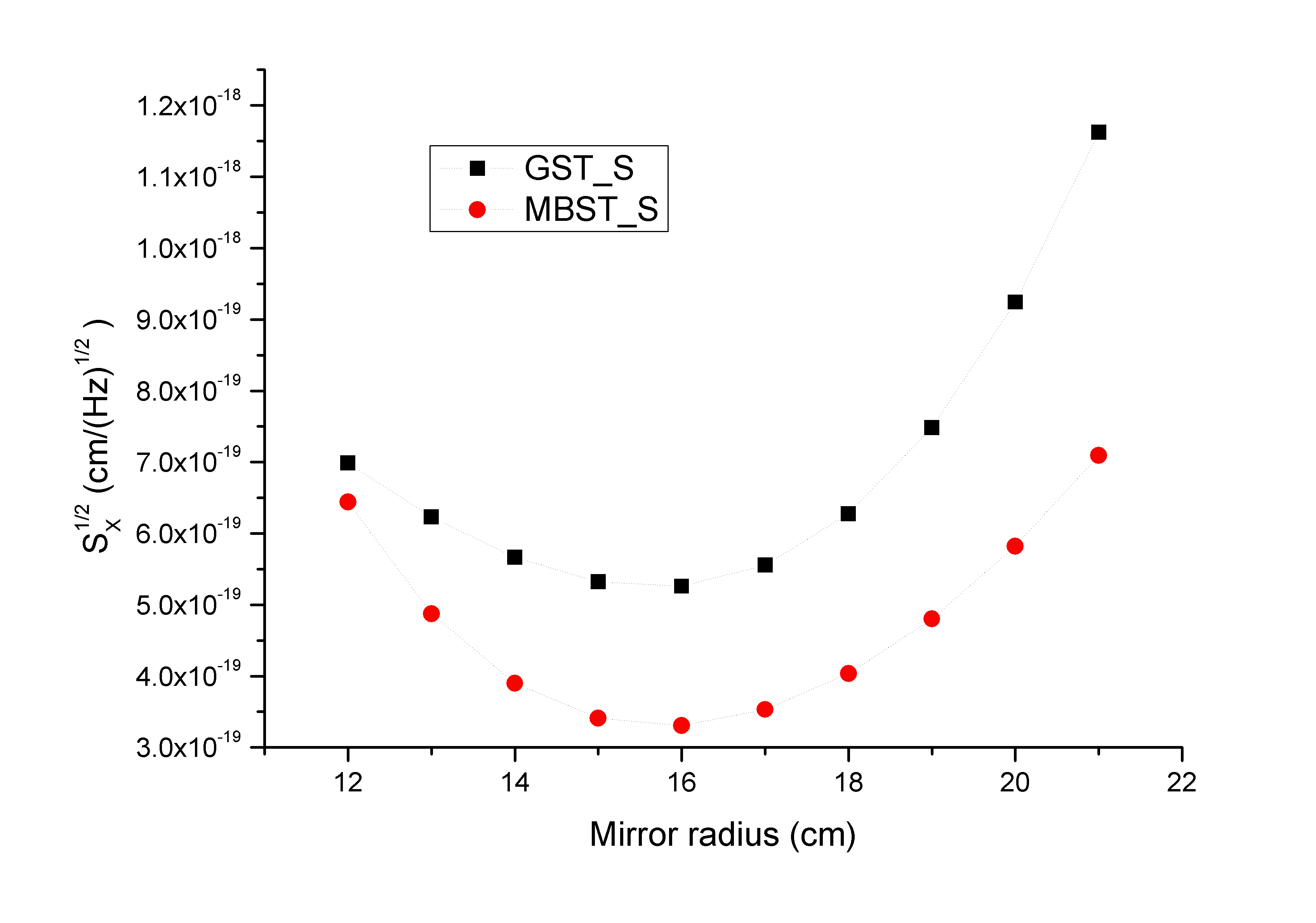
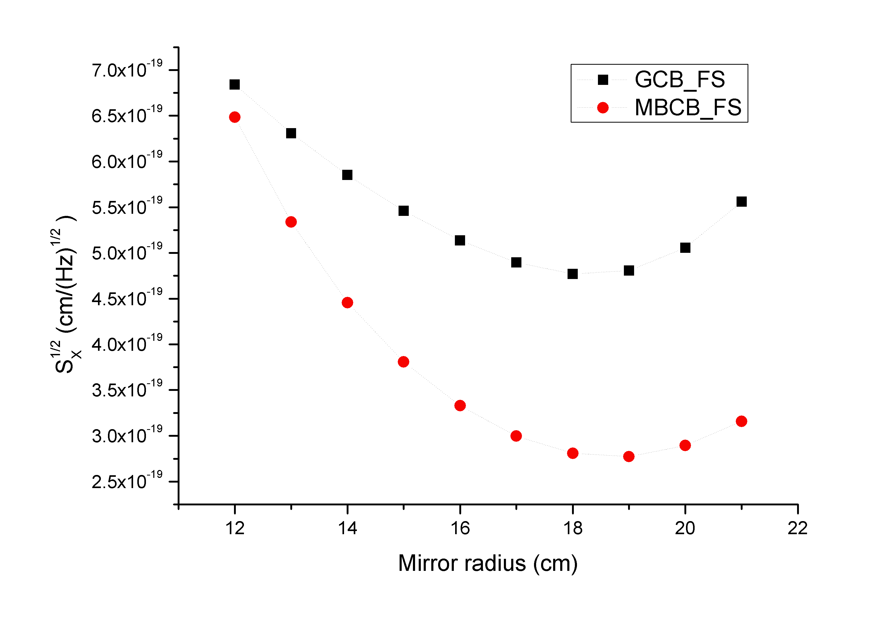
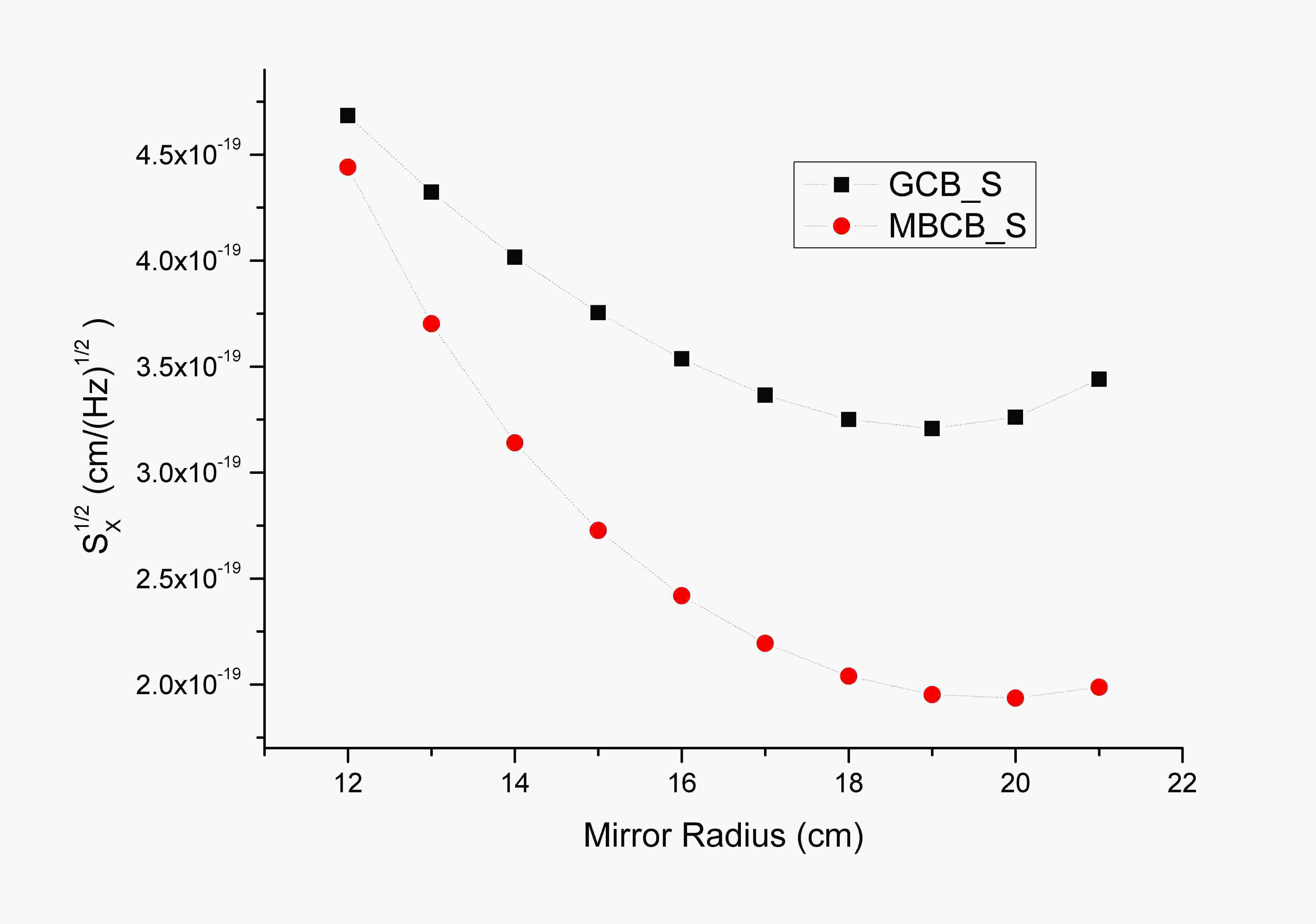
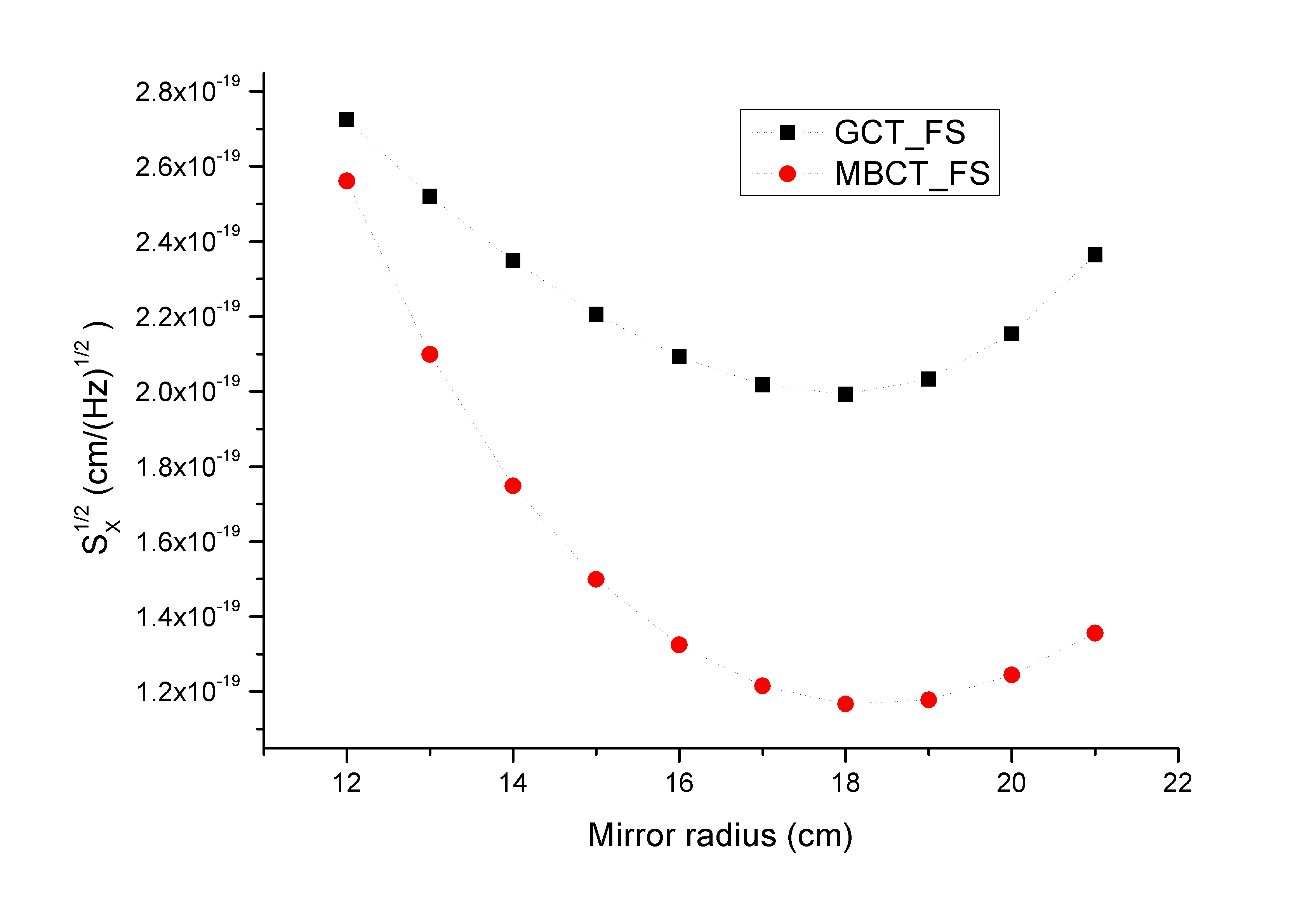
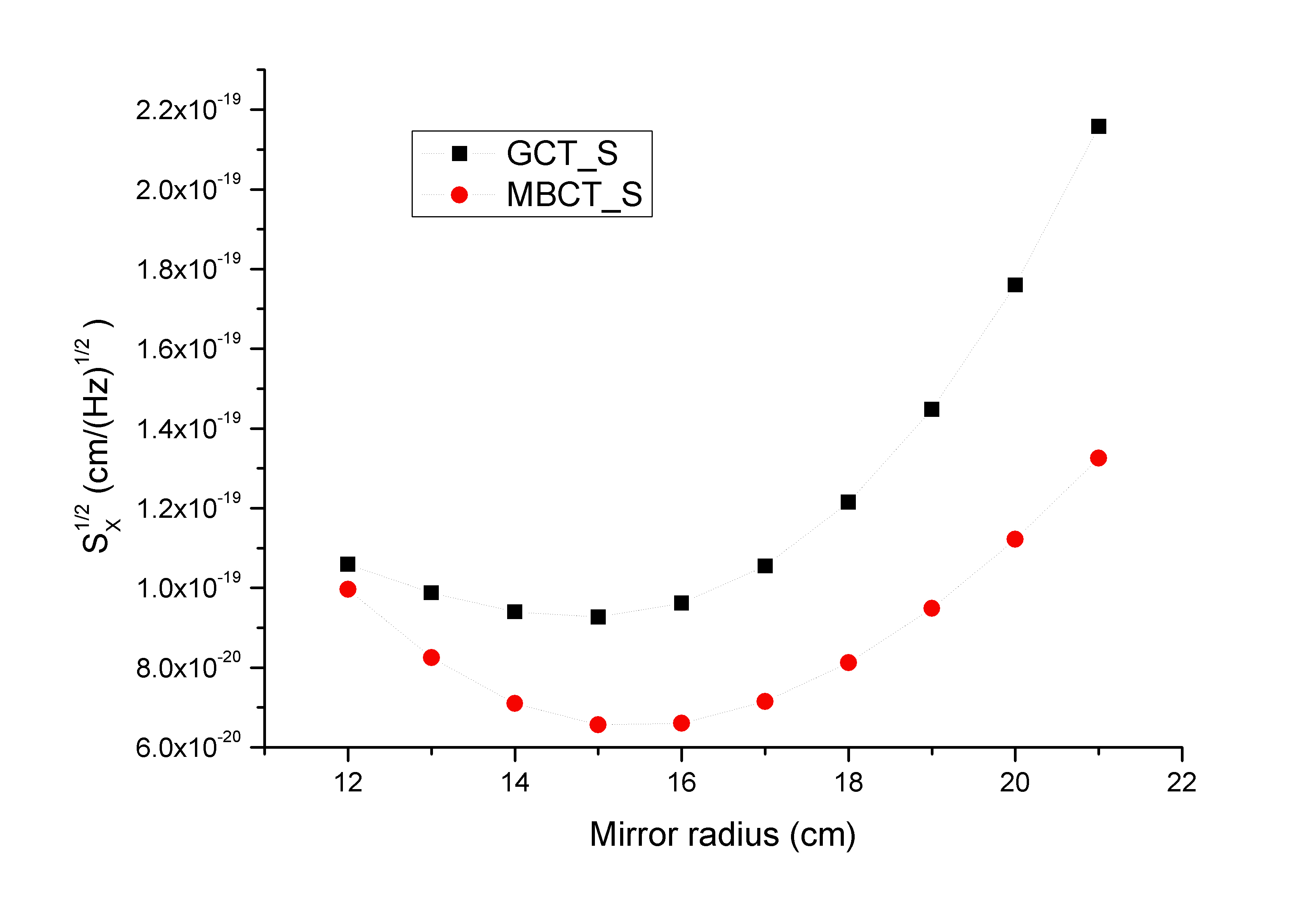
It is interesting to note that all the thermal noise contributions present a minimum in the finite cylindrical model. The minimum of the sum of all contributions represents the best choice for the mirror and beam dimensions. The descent part of the noise curves reflects the basic idea that increasing the beam radius the noise will get lower and the rising part of the curves can be explained heuristically by the fact that all the noises contributions are related somehow to the amplitude of the elastic deformation of the test mass under a surface pressure and this effect is larger in gong-shaped mirrors than in bar-shaped ones.
From the incoherent sum of the four contributions we have that minimum thermal noise occurs for a mirror radius of about 18 cm for Gaussian beam and for about 19 cm for Mesa beam. The corresponding mirror aspect ratios ( ) are for Gaussian beam and for Mesa beam. The aspect ratio chosen for Advanced LIGO baseline is . For this geometry the gain in sensitivity is about a factor 1.7 switching from Gaussian to Mesa beam at the minima of thermal noise (see Fig. 4.7).
Fig.4.6 shows the expected sensitivity of Advanced LIGO interferometer in the Gaussian or Mesa beam configuration calculated with Bench101010Bench is a simulation program available at http://emvogil-3.mit.edu/bench/. The estimated range for NS-NS binary systems increases from for Gaussian beam to for Mesa beam. This is a remarkable factor if we consider that we didn’t optimize the other interferometer’s parameters to take full advantage of the reduced mirror thermal noise floor. In this evaluation the thermo-refractive noise of the coating was taken into account as discussed in Sec. 4.8.2.6.
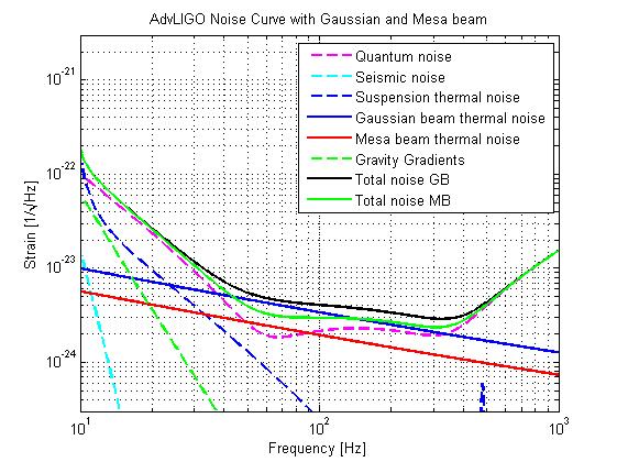
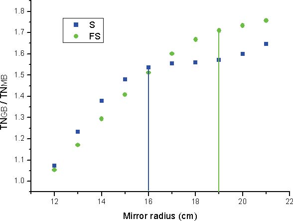
4.8.3.2 Sapphire substrate
We have conducted the same kind of analysis for mirrors with Sapphire substrate. This study was made mainly for historical reasons as the idea of using sapphire substrates for the mirrors is now abandoned. In this case the dominant noise is the substrate thermo-elastic contribution. Some of the advantages of using Mesa bean have been already analyzed in oshaug for this particular noise source. Here we compute the various thermal noise contribution for finite size test mass and show the relative gain for each thermal noise employing a Mesa beam instead of a standard Gaussian. For Kg sapphire substrates the minimum of thermal noise occurs for a mirror radius of about 16 cm. The corresponding mirror aspect ratio () is about . The total thermal noise reduction for Mesa beam is about a factor around the minimum.
4.8.4 Further consideration
4.8.4.1 Finite size effect
We first want to give a quantitative estimation of the finite test mass (FTM) effect on the different kinds of thermal noise. In Fig. 4.8 we plot the fractional correction provided by our analysis with respect to the formulas found in literature for Gaussian beams in the semi-infinite mirror case. For mirror radius of cm, which provides the minimum of thermal noise, the correction is around for substrate Brownian and less than for the other contributions.
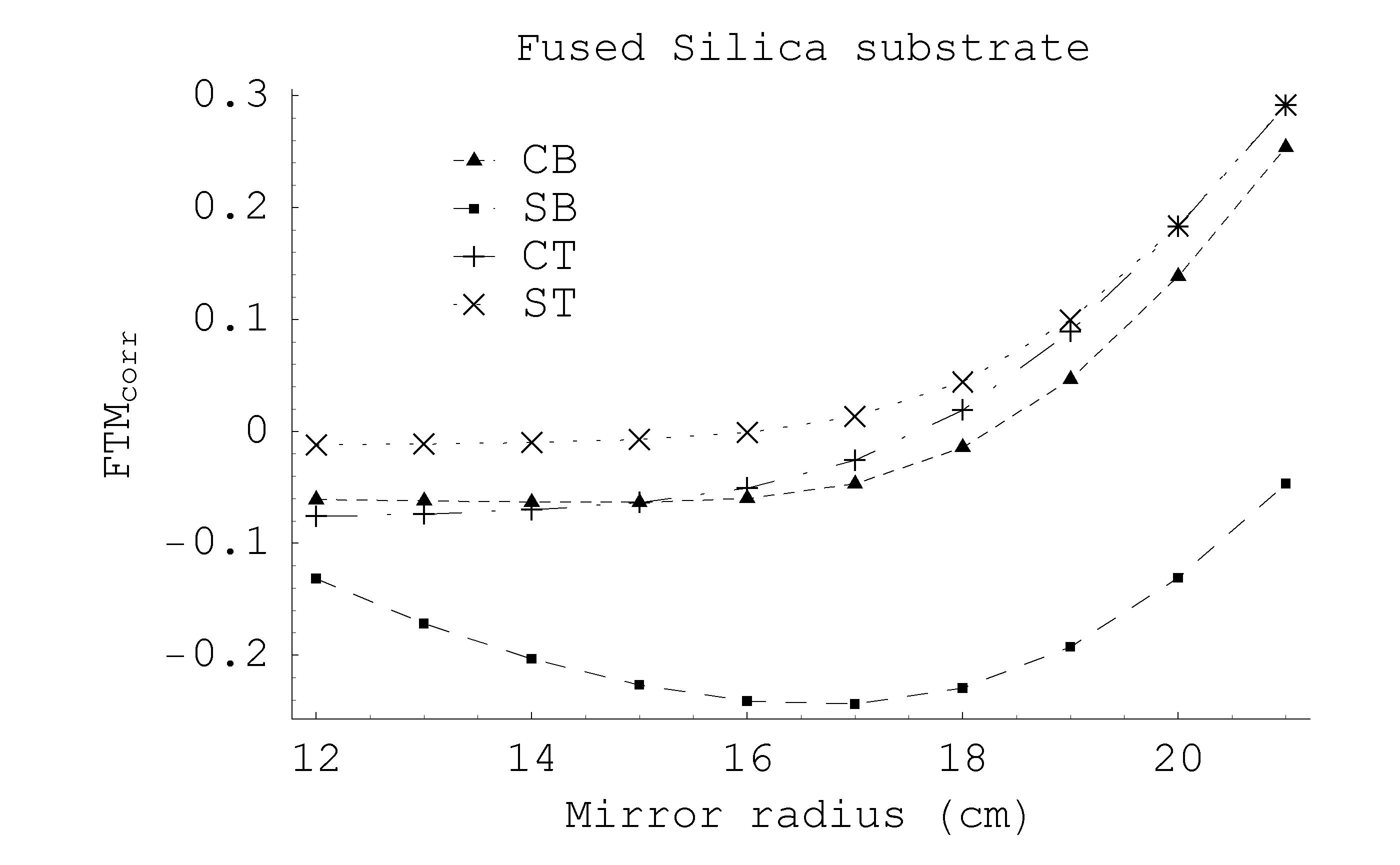
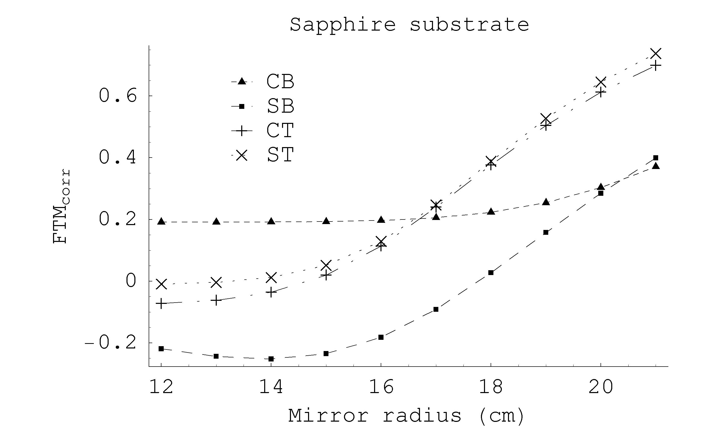
Lovelace Lovelace performed the computation of simple scaling laws for thermal noise with arbitrary beam shapes and semi-infinite mirrors. He also analyzed the finite test mass correction provided by our results with respect to his derivation in the case of mesa beam and the conclusions are similar to the FTM effect for Gaussian beam.
4.8.4.2 High order LG modes
It has been recently proposed vinetLG the use of high order LG beams and excited modes of meas beams to reduce the thermal noise in interferometric GW detectors. The problem is that although these kind of beam provide a comparable reduction of the substrate thermal noises with respect to the mesa beam, they are sensibly worse than the mesa beam for the dominant coating thermal noises. The radial nodes of the higher order LG beam, cause rapidly variation of the elastic field near the coating surface. This produces an higher elastic energy density stored in the coating, which boosts the coating Brownian thermal noise, and higher thermal gradients, which are responsible for the thermoelastic noise. To substantiate these considerations we shown a comparison in the elastic energy distribution inside the mirror between a standard Gaussian beam, a mesa beam and a mode, all with ppm of diffraction losses.
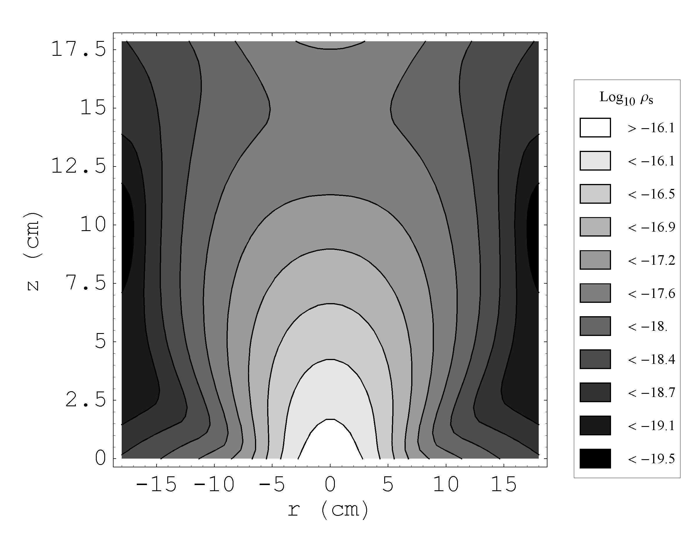
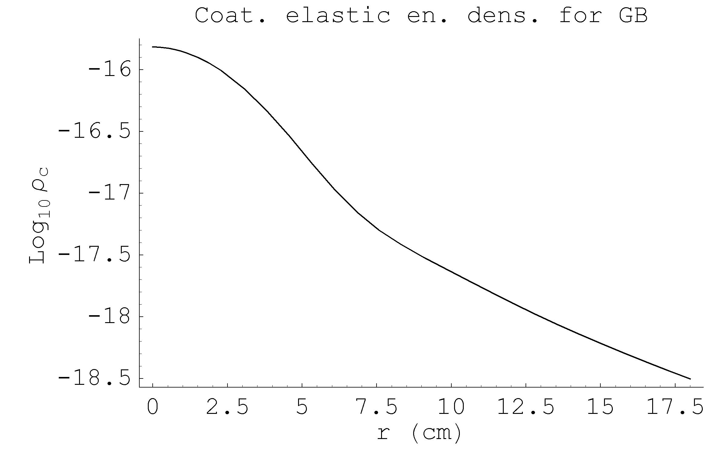
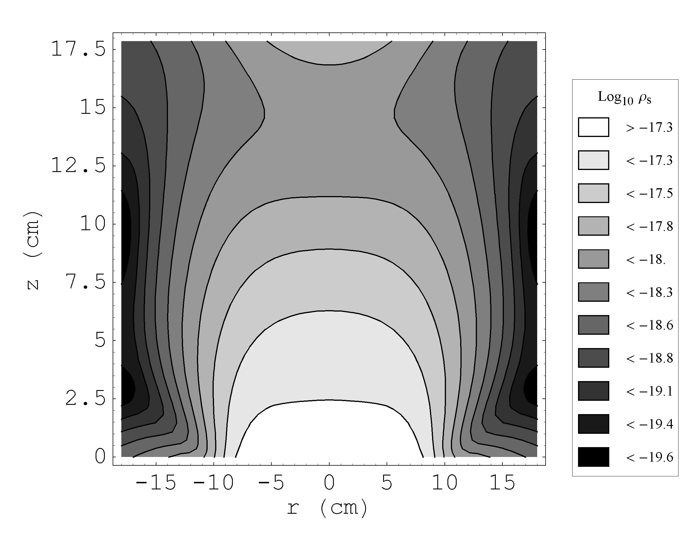
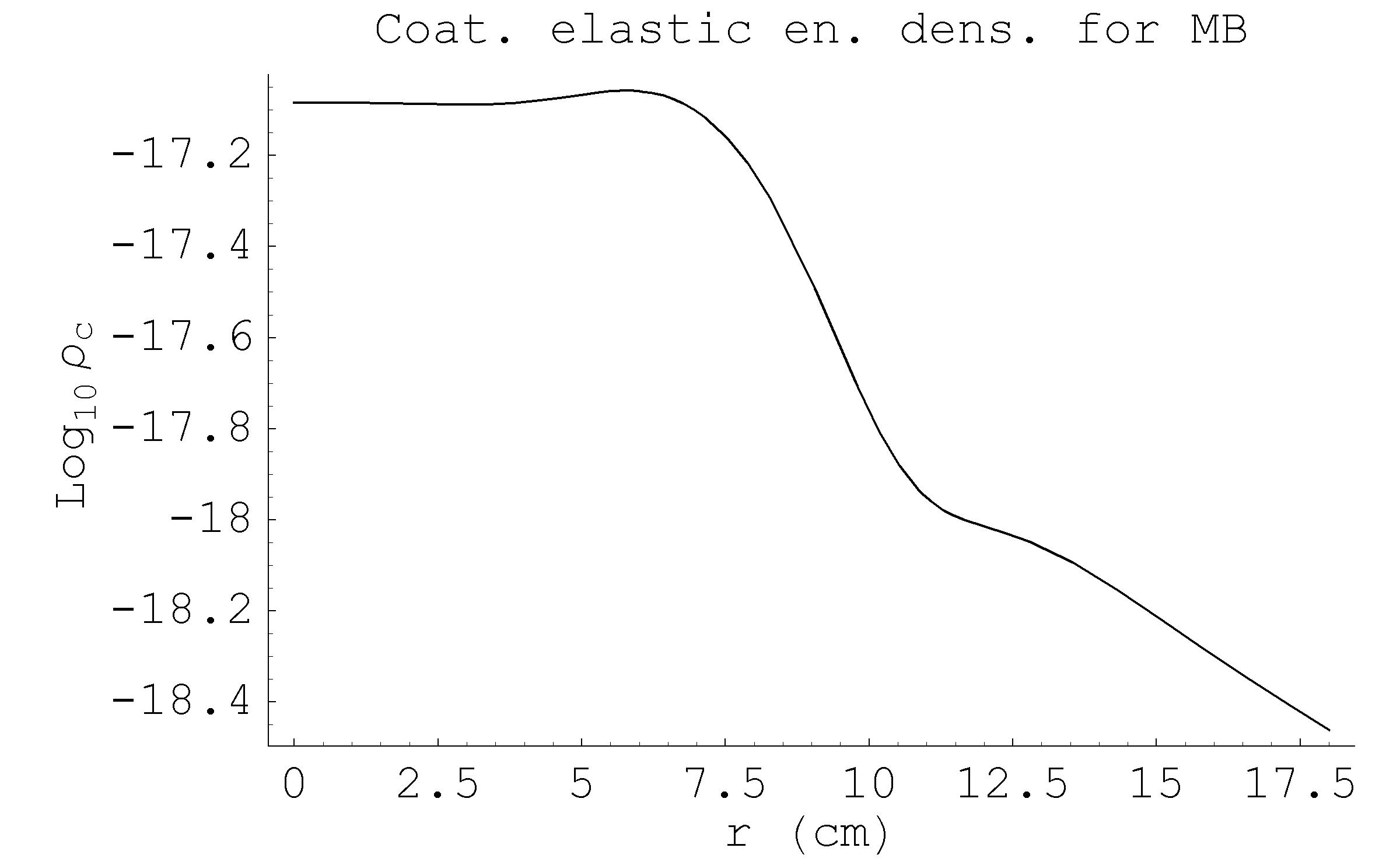
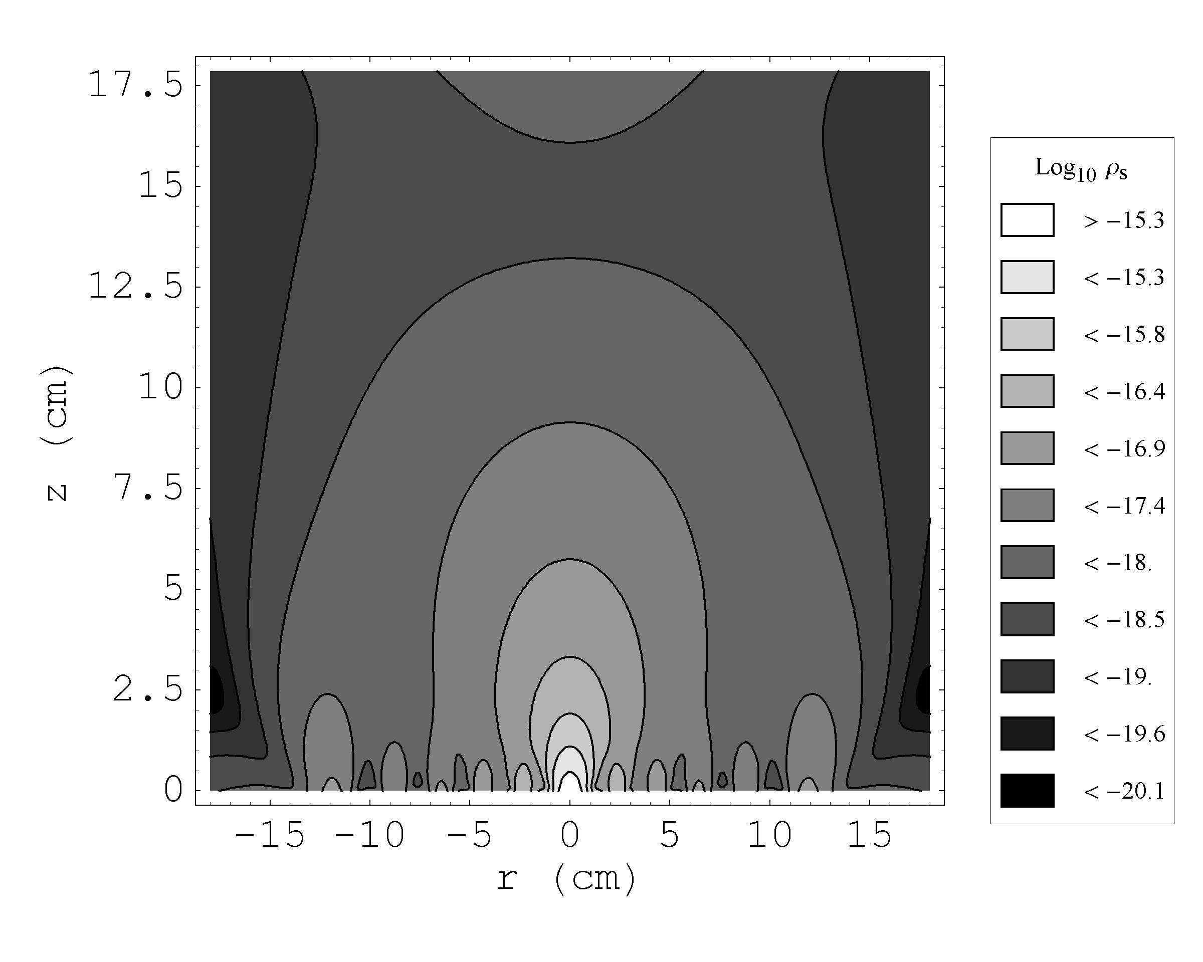
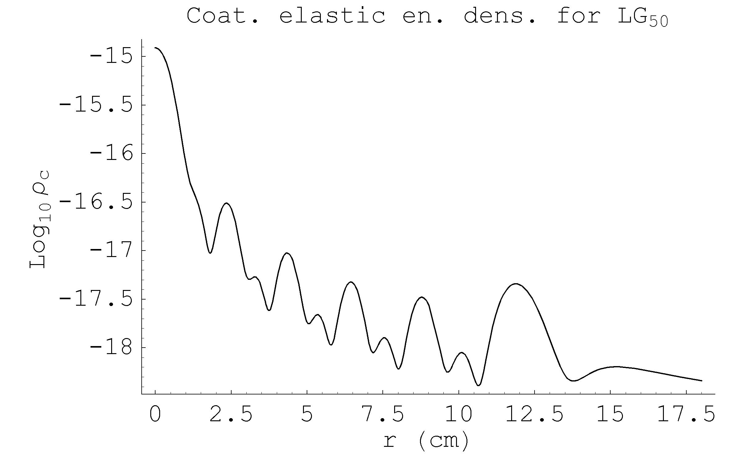
| Noise | GB | MB | LG50 |
|---|---|---|---|
| CB | |||
| CT |
Because of the ripples in the elastic energy distribution, we expect the coating thermoelatic noise for the higher order Laguerre Gauss beams to become large in the low GW signal frequency regime. The characteristic thermal diffusivity length increases as the sensitivity frequency decreases, in such a way that the temperature fluctuations involves a larger volume of the test mass. In Fig. 4.12 we show the comparison between the Gaussian, mesa, and beams with respect to the coating thermoelatic noise. At low frequency ( Hz) the noise is almost three times larger than for Gaussian beam, which remains a factor of two above the mesa beam noise.
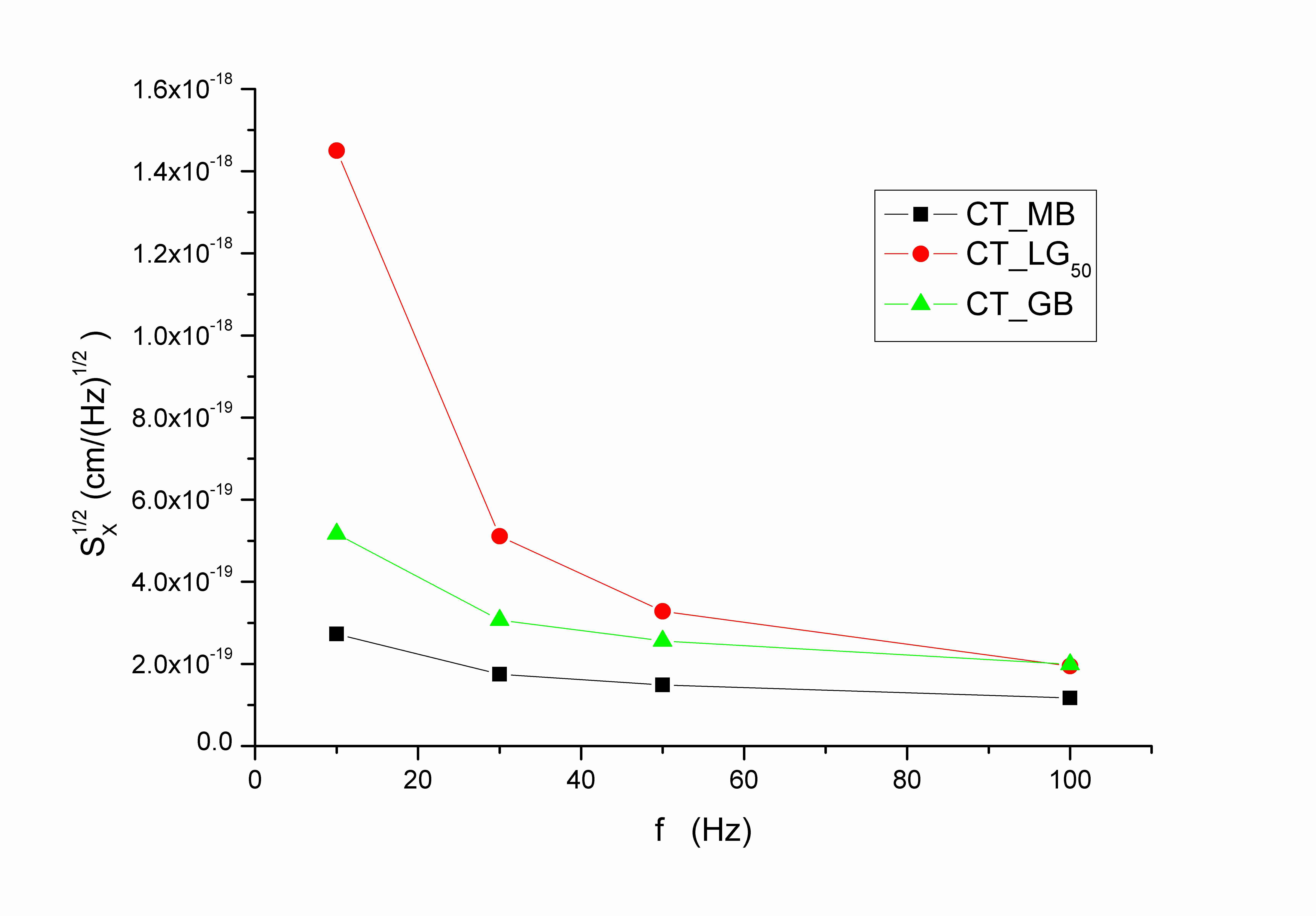
4.9 Optimized coating
The limit sensitivity of interferometric gravitational wave antennas is set by the thermal noise generated in the dielectric mirror coatings. These coatings are currently made of alternating low-loss quarter-wavelength high/low index material layers. This design yields the maximum reflectivity for a fixed number of layers, but not the lowest noise for a prescribed reflectivity.
Realization that much of the thermal noise in the coating comes from the material of the high index layerPenn-loss2 has lead to investigation of optimizing the individual layer thicknesses while preserving the needed reflectivity. This motivated our recent investigation111111 In collaboration with the Waves Group, Department of Engineering, University of Sannio, Benevento, Italy. of optimal coating configurations, to guarantee the lowest thermal noise for a targeted reflectivity. This communication provides a compact overview of our results, involving truncated periodically-layered configurations121212More general analysis involving nonperiodic genetically-engineered coatings has been presented in SPIEcoat . Possible implications for the advanced Laser Interferometer Gravitational wave Observatory (LIGO) are discussed.
All interferometers presently in operation use quarter-wavelength (QWL) designs, which are known (Bragg theorem) to be optimal, in the sense that they yield the largest reflectivity for any fixed number of layers (or, equivalently, the smallest number of layers for any prescribed reflectivity). However, QWL coatings do not yield the minimum TN for a prescribed reflectivity, and hence are not optimal for GW interferometers, where the quantity that should be maximized is the visibility distance of the instrument, which in its turn is limited by the coating thermal noise.
This section addresses the above optimization problem, and is organized as follows. We outline our comprehensive working model for the multilayer mirror reflectivity and Thermal noise. Than we present an examples of optimized coatings, focusing on periodic stacked-doublet multilayers, and compare them with the standard QWL syntheses. Conclusions and recommendations follow in the end of this section.
4.9.1 Multilayer Coating Reflectivity
We consider a planar multilayer dielectric coating composed of alternating homogeneous layers (with variable thickness) of silica () and tantala (), illuminated by a normally-incident plane wave, with implied time-harmonic dependence. Referring to Fig. 4.13, we consider layers, interfaces, and four dielectric media, including the left and right semi-infinite media and (vacuum and substrate).
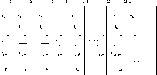
The incident and reflected fields are considered at the left of each interface. The overall reflection response, , can be obtained recursively in a variety of ways, such as the propagation matrices, the propagation of the impedances at the interfaces, or the propagation of the reflection responses Orfanidis . The elementary reflection coefficients from the left of each interface are defined in terms of the refractive indices as follows:
| (4.88) |
where and . The forward/backward fields at the left of interface i are related to those at the left of interface by:
where is the phase thickness of the layer, which can be expressed in terms of its optical thickness and the operating free-space wavelength by . The reflection responses will satisfy the recursions:
| (4.89) |
and initialized by . The mirror reflectivity is given by . It is useful for the following analysis to introduce the scaled optical length .
The above formalism can be easily generalized Orfanidis to the case of oblique incidence, via the introduction of (polarization dependent) “transverse” wave-impedances and refractive indexes.
4.9.2 Multilayer Coating Thermal Noise
Since the function we want to minimize is the coating thermal noise, we need the most accurate description of the thermal noise for a multilayer structure. Eq. (4.7.0.1) has been generalized by Harry Harry-anisot in order to incorporate coating anisotropy into the thermal noise. A multi layer structure composed of alternating layers of homogeneous materials exhibits a mechanical behavior proper of a transversely isotropic material in which the independent elastic coefficient in the stiffness matrix (4.19) are reduced to five by the rotational symmetry around the axis orthogonal to the layers. and are the Young modulus for stress causing strains entirely within the plane parallel to the coating layers or perpendicular to this one. There are also two Poisson ratios, for stresses and strains both with the plane parallel to the coating layers, and for when either the stress or the strain is perpendicular to the coating layers. The displacement induced noise is given by
| (4.90) |
where the loss angle depends on the coating thickness , on the beam radius , and on the loss angles in the parallel and perpendicular direction with some coefficients dependent on the elastic coefficient of the coating and substrate
| (4.91) | |||||
In the paper Harry-anisot , , are calculated from the values of the isotropic materials that makes up the layers of the coating in the following way
solution of
When we first looked at the problem of coating optimization, we were not completely satisfied with the derivation of the averaged mechanical properties of the multi-layer coating quoted above. Therefore we put some effort in the rigorous analysis of a multi-layer structure and the results are presented in the following section.
4.10 Averaged elastic coefficients for multilayered optical coating
Heterogeneity of a material or structure can be caused by two main reasons.
-
1.
Non-uniformity of certain physical characteristic (density, elastic modulus, conductivity, etc. ). Two or multi-phase composites are typical examples of this type of material behavior.
-
2.
An additional source of heterogeneity is a geometrical one. A multi-layer structure like the dielectric optical coating used in gravitational waves interferometers is an example of this effect.
The replacement of heterogeneous media by an homogeneous continuum, which is characterized by certain effective constitutive equations, is the basic instrument for the effective media theory (EMT), which is a well developed subject in composite mechanics heterogeneous . The purpose of this section is to give a mathematical introduction to the problem of the calculation of mechanical properties of heterogeneous solids with periodic microstructure. The averaging procedure for mechanical fields and the definitions for effective constitutive parameters (effective elastic moduli, for instance) are described in the following for a bilayered composite medium. We provide a rigorous derivation of the coating effective mechanical parameters which is very important in the study of coating optimization for GW interferometers.
Let us consider an elastic solid which consists of a periodic array of two layers with thicknesses and , respectively in welded contact and stacked in the direction. It means that the components, , of the elastic moduli tensor, which link strains , and stresses, are periodic functions, . Let us define the average over the unit cell, composed dy a bilayer structure, as
One can introduce the definition of the effective moduli tensor as the coefficients which link the components of effective fields variables defined by averaging the strain and stress tensor and taking into account the continuity conditions at the interface between the two layers. We skip all the mathematical technicalities, referring the reader to heterogeneous ; Wavepropag and we report only the results of the homogenization process
| (4.92) |
It is interesting to point to the direct averaging law for the composite planar shear modulus and the inverse averaging law for the transverse ones: .
The constitutive relations for each of the two assumed isotropic materials are given by (4.23) as functions of the two Lamè coefficients. In a cartesian coordinate system, the components of the stiffness tensor are
| (4.93) |
Let us remind in Tab.4.3 the relation between the Lamé coefficients and the Young and Poisson coefficient for an isotropic material
Since both materials are assumed isotropic, the resulting layered medium is expected to posses transverse isotropy with isotropy confined in the plane. Even in an anisotropic medium, the axial components of the stiffness tensor are frequently characterized by the parameters of uniaxial tension, namely Young modulus , and the Poisson ratio , for the tension in the direction:
| (4.94) |
These parameters can be easily calculated for the homogenized compound material by means of the components of the effective stiffness tensor
| (4.95) | |||
| (4.96) |
Planar, and transverse , Young moduli, share moduli and Poisson ratios of binary multilayered coating composed of and are shown in fig. REF as functions of the layer thickness fraction. The explicit expressions of the elastic coefficient of the multilayer structure as function of the elastic coefficients of the two material are
| (4.97) | ||||
| (4.98) | ||||
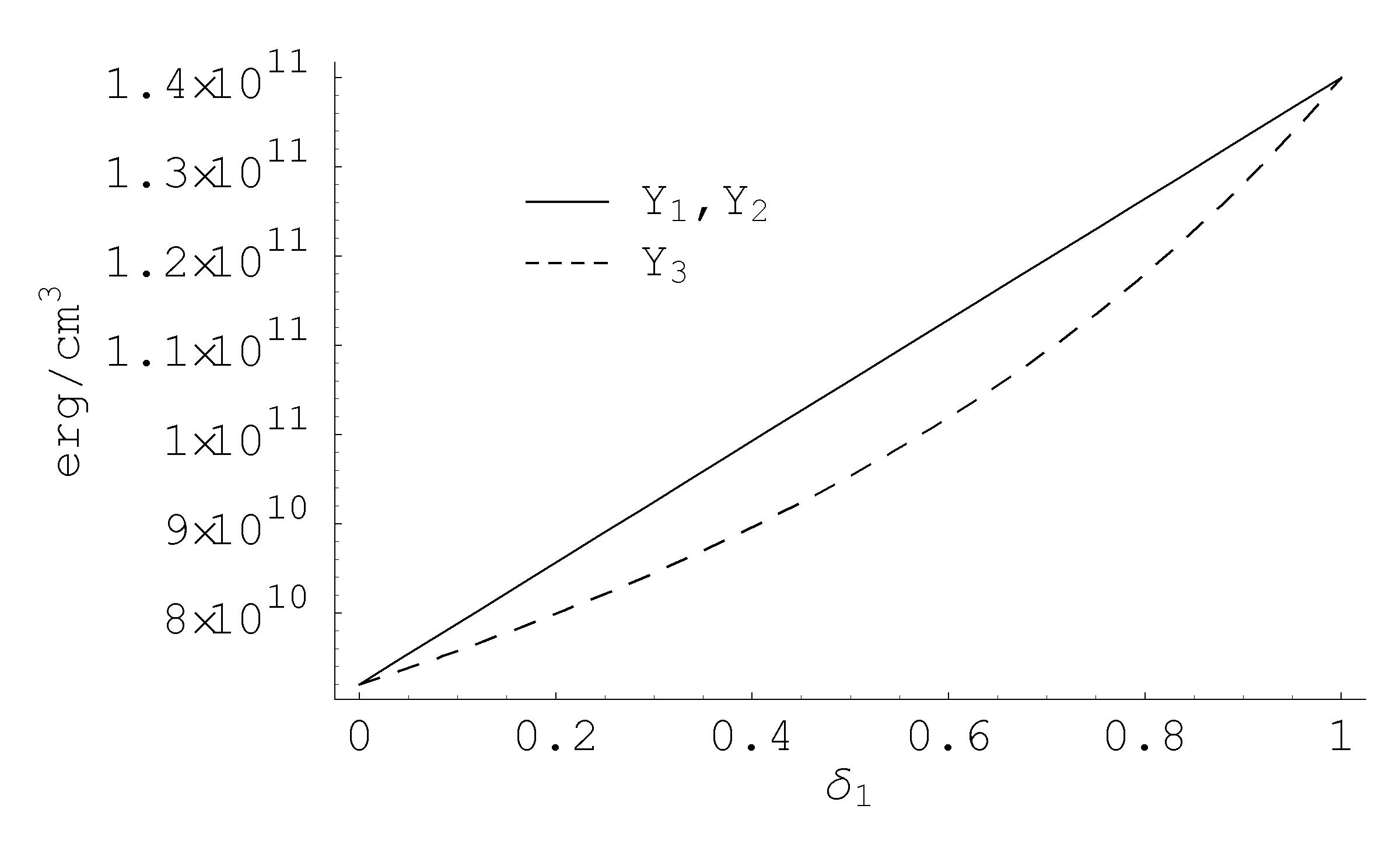
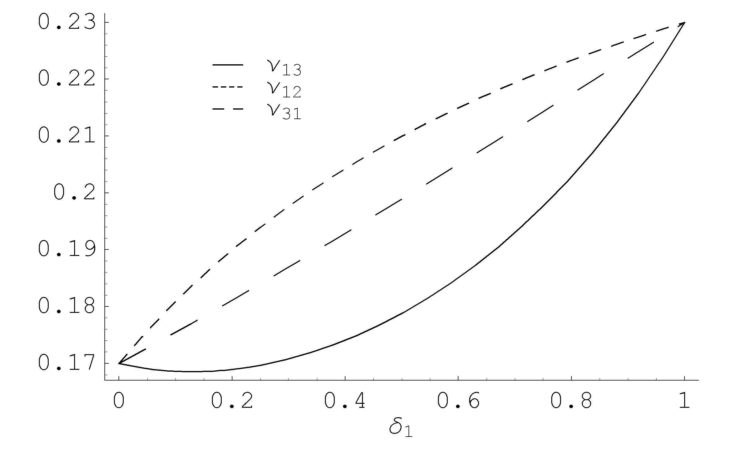
By convention, the elastic constants in transverse isotropic constitutive equations are the Young’s modulus and Poisson ratio in the x-y symmetry plane, and , the Young’s modulus and Poisson ratio in the z-direction, and , and the shear modulus in the z-direction . The compliance matrix takes the form
Let us now expand the exact expressions of the Young and Poisson averaged coefficient, Eqs. (4.97),(4.98), in power series of the two material’s Poisson coefficient and
| (4.99) | ||||
These more manageable expressions131313The firsts two expression reproduce the results of Harry-anisot , whereas the other two are different. offer excellent approximation for typical LIGO mirrors coating: for the standard quarter wavelength design, the difference between the approximated values and the exact values is within .
4.11 Thermal noise for an anisotropic coating
The thermal noise for a semi-infinite mirror with an anisotropic coating is given by 141414This is a corrected form of the equation in Harry-anisot .
| (4.100) |
| (4.101) |
In the limit of isotropic coating this formula reduces to (4.7.0.1). Since the loss angle is introduced in the theory of elasticity as an imaginary part of the elastic coefficient of the material, it is natural to obtain the values of and from the isotropic values , using the same averaging rules as the Young moduli. Therefore we have
| (4.102) |
and the expansion in the Poisson coefficients gives
| (4.103) |
We now have all the ingredient to express the coating thermal noise as function of the characteristic elastic coefficient of the substrate and coating materials, which for the present analysis will be treated as constants, and the thickness, , and the number of doublet, of the layers. The function results in a complicated expression which is not particulary illuminating and its analytical form will be omitted in this presentation. However we can give a very good approximation of this function by a first order Taylor expansion around the point which correspond to the standard design, , where is the scaled optical path .
| (4.104) |
Fig.4.15(left panel) shows the accuracy level of this linear approximation. If we are looking for an analytical approximated expression we can take the limit of vanishing Poisson ratios in the general expression of the noise and then take the linear terms in the two optical thickness
| (4.105) |
From Fig.4.15(right panel) we can easily see that even if the expression above is very manageable, it provides a rough approximation of the exact formula and it leads to error above in the interesting region.
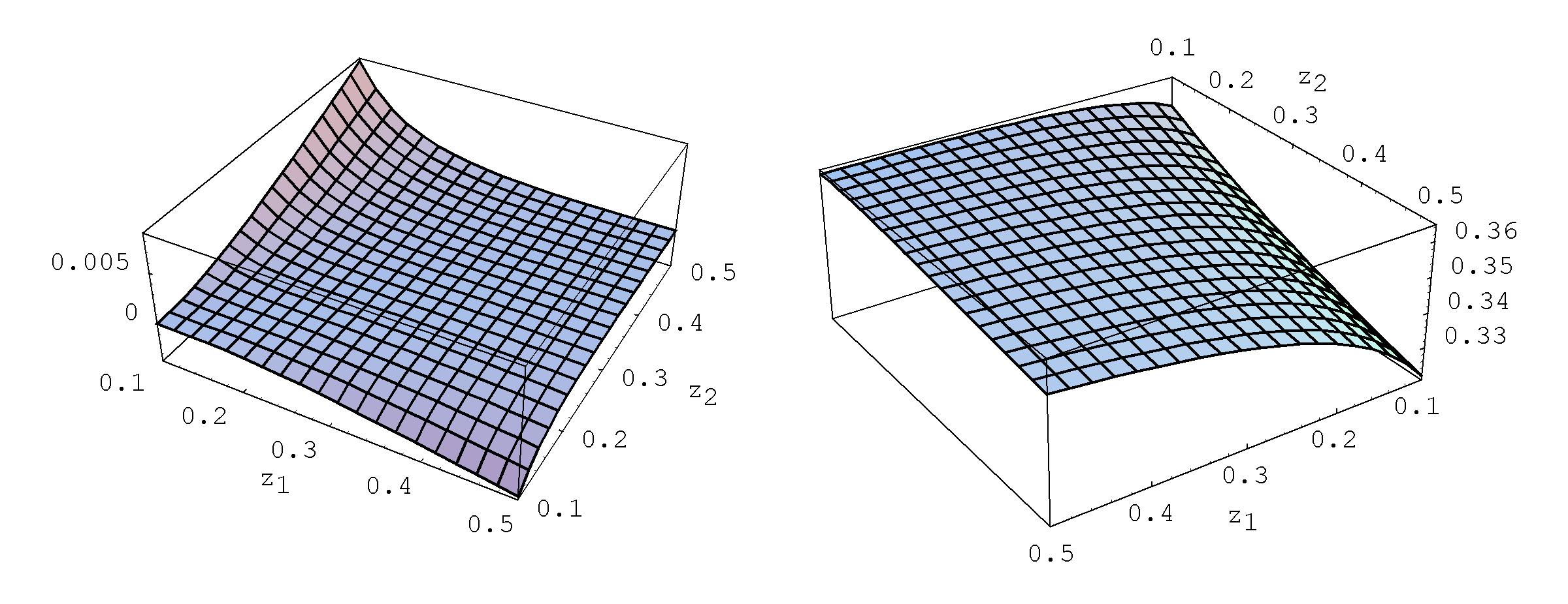
4.12 Coating thickness optimization
Our collaborators from the University of Sannio, Benevento, developed an analysis based on genetic algorithm (GA) to address the problem of finding the best coating design for minimizing the thermal noise. We briefly review their conclusions, in order to validate our simple direct optimization. Genetic algorithms (GAs)
GAs have proven as effective tools for synthesizing general (e.g., multi-dielectric) reflective coatings, featuring several heterogeneous (e.g., technological) design constraints, with multiobjective (i.e., reflectivity and thermal noise) optimization targets. The general analysis led to the result that, as the number of generations is increased, the centermost part of the GA-optimized coatings exhibits a neat tendency toward a cascade of almost identical doublets, whose (total) optical lengths cluster around . The above findings led us to investigate the performance of coatings composed of cascaded identical multiplets with the constraint . This constraint reduces the number of independent variables to two, and , the optical thickness of the high index material and the number of doublets.
Fig. 4.16 shows the noise function scaled to the Ad-LIGO baseline value, and in the range of interest.
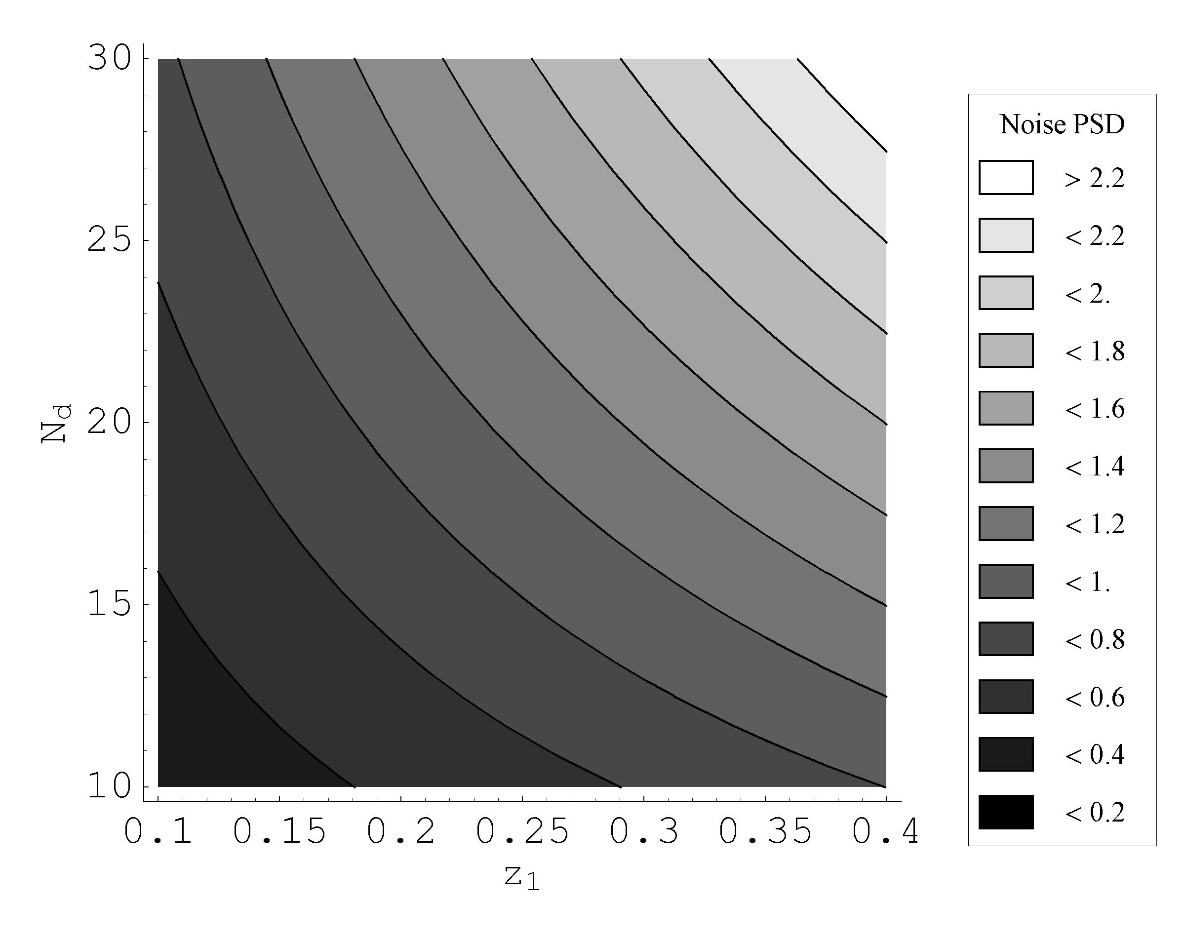
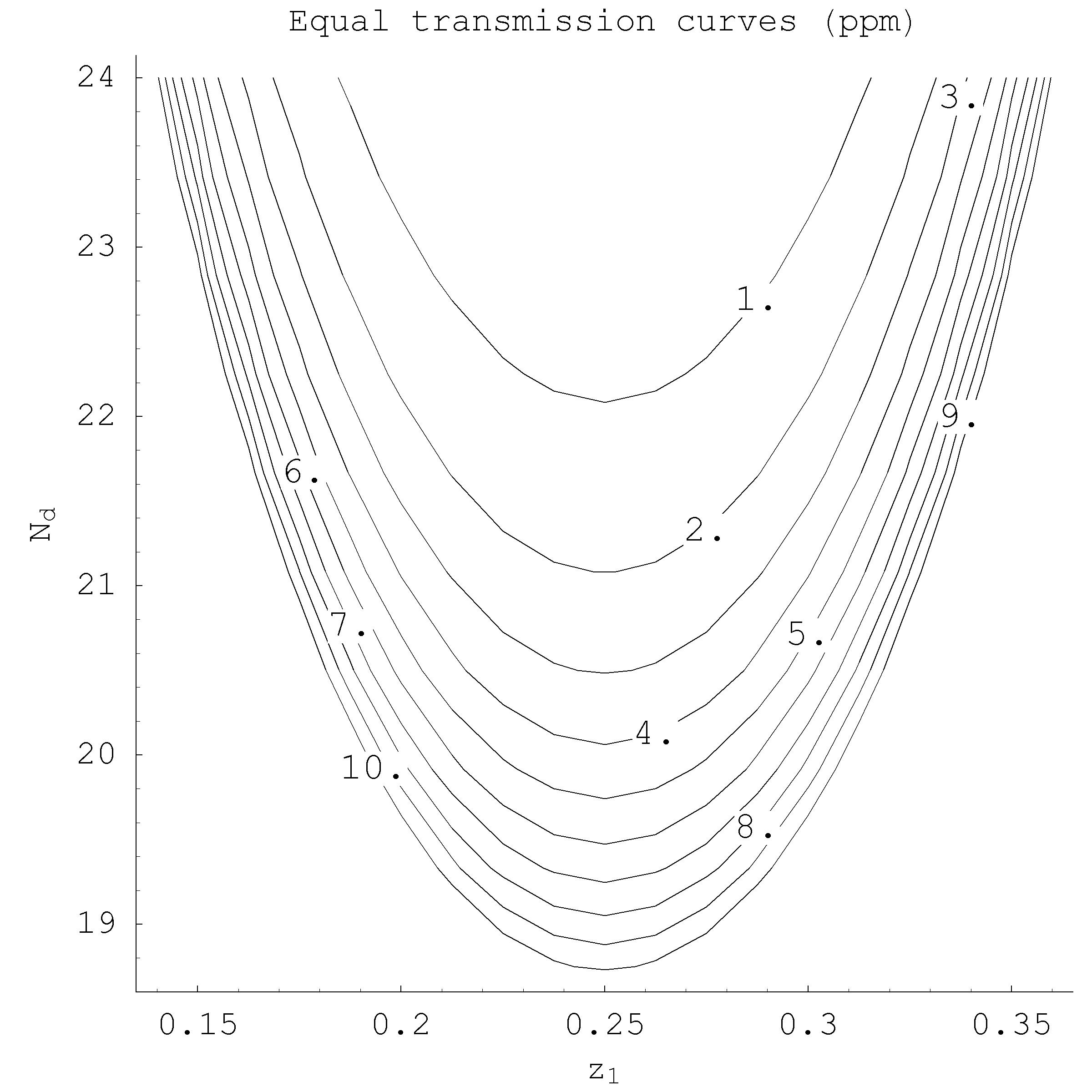
We followed the strategy:
-
•
Calculate the coating transmission 151515In the absence of (optical) losses. for the baseline design, , using Eq.(4.89):
-
•
In the plane , draw the curve of equal transmission constrained by the above value.
-
•
Plot the noise function in the same graph and find the point on the above curve which correspond to the minimum noise. This correspond to the optimized design .
All the procedure is synthesized in Fig.4.17. The optimized design (for the known values of material losses, elastic moduli, etc.) is given by , and ; for the same optical transmission of the -design, it provides a of reduction in noise spectral density. Under the simplest assumption where the GW sources are distributed homogeneously/isotropically throughout space, without interferometer re-optimization, this may boost the event rate by some .
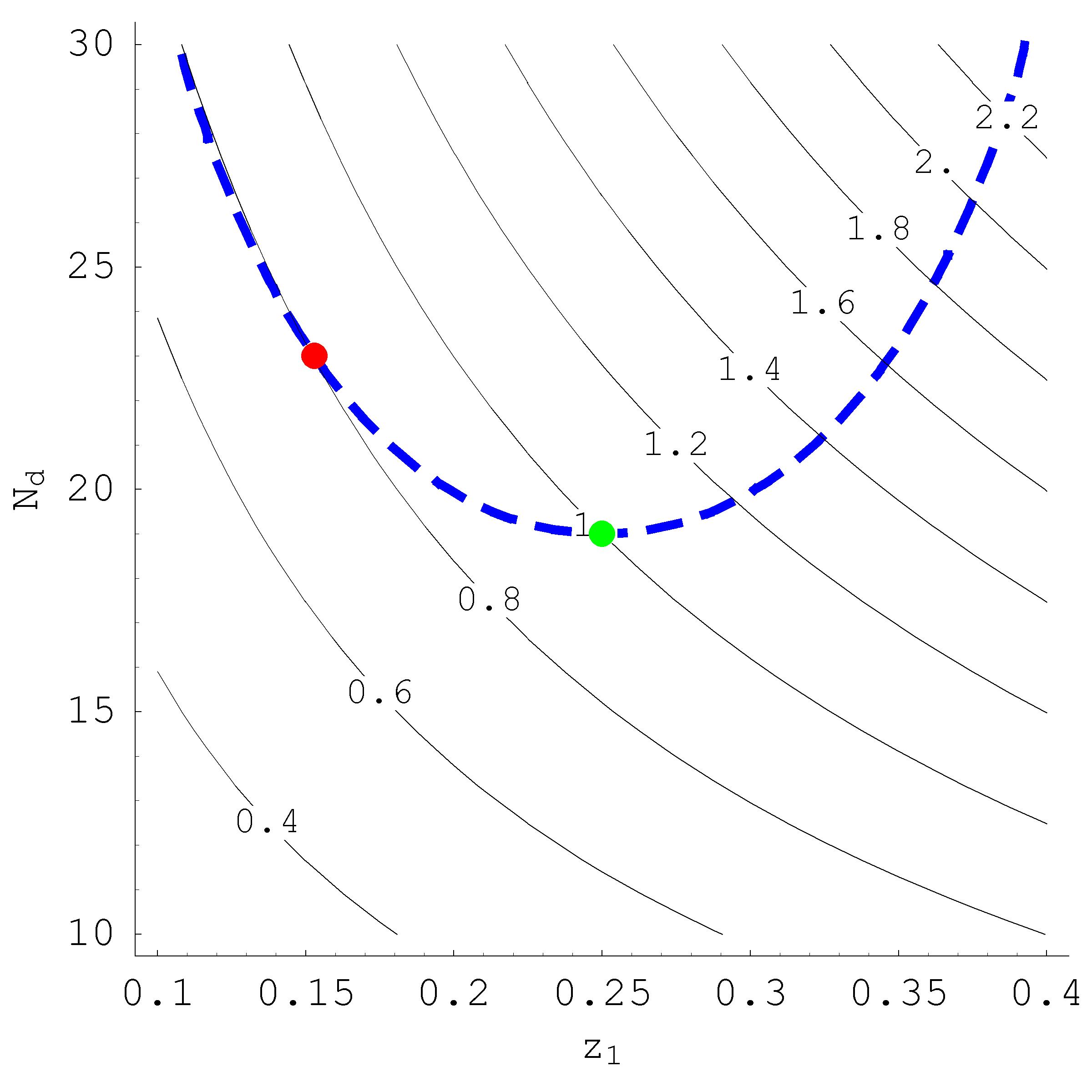
The optimization of the coating structure to minimize the thermal noise is therefore a very promising idea, which in principle could stand beside the mesa beam proposal, increasing further the detector sensitivity. Coating thickness optimization should be considered as almost mandatory to minimize coating noise, yielding in all cases161616In this thesis we have focused the attention on the Brownian coating thermal noise, but on-going researches Castaldi have analyzed the total coating noise budget and provided the corresponding optimized design. a substantial increase( at Hz) in the expected event rate, as compared to the QWL design. A prototype of optimized coating has been designed by our collaboration and is scheduled for testing at Caltech in the TNI (Thermal Noise Interferometer) facility. LMA is responsible for manufacturing the sample, using the ion beam deposition techniques.
Chapter 5 Conclusions
This thesis presents a collection of different researches on non-standard optics in view of enhancing the performances of the Advanced Gravitational waves interferometric detectors.
Although primarily based on simulations, calculations and theoretical arguments, this work has been in continuous feedback with the experimental side of the thermal noise minimization effort. This work has provided the theoretical understanding and guidance for the experimental side, while getting back continuous and progressive validation of the predictions and prescriptions. The end result was a very good example of synergy, and mutual enrichment, for me and my introduction to laboratory work, and for my colleagues that worked on my prescriptions and numbers.
In the design of the next generation Gravitational Waves interferometric detectors, mirror’s thermal noise plays a crucial role. The mirrors coating thermal noise is expected to be the limiting factor in the GW signal frequency region of highest sensitivity.
The quest for increasing the event rate in the observational band has motivated the exploration of various techniques for reducing the mirror thermal noise toward the development of second-generation detectors, such as Advanced-LIGO AdLIGO . With specific reference to the coating Brownian noise (dominant in the current baseline design featuring fused-silica test masses), use of improved (low-mechanical-loss) materials, geometric optimization of the coating design, and flat-top (commonly referred to as “mesa”) beams seem the most promising. The latter option, intuitively motivated by the potential capability of a mesa beam (MB) of better averaging the thermally induced mirror surface fluctuations as compared to a standard Gaussian beam (GB), has been numerically proved in this thesis to yield significant reductions in the overall thermal noise. For the first time we calculated the coating types of thermal noise reduction in using mesa beam and enlightened the issue of mirror geometric aspect ratio optimization. We demonstrated that the coating induced displacement noise can be reduced by a factor of which increases the estimated binary neutron star inspiral range 111The effective range conventionally measures the sensitivity of the interferometers to signals arising from binary systems composed of solar mass neutron star pairs having a signal-to-noise ratio of or better, and is computed by averaging over both the antenna sensitivity pattern and over all possible orientations of the binary systems., seen by Ad-LIGO, from Mpc to Mpc.
During this work we implemented the different kinds of thermal noise calculations for finite size test mass and arbitrary cylindrically-shaped laser beams, in a simple notebook called Thermal Noise Notebook (TNN). This package is available as a very simple tool for the estimation of the thermal noise contributions taking into account both the beam and the mirror geometry. We illustrated the importance of uniform sampling of the mirror surface to reduce thermal noise and the limitation brought by the use of excited modes with nodes on the mirror surface, which cause non-negligible gradients in the elastic and thermal fields in the test mass and worsen the thermal noise performance.
In Sec.3.4 we further developed the theory of mesa beam and derived some unexplored analytical results for the dual configuration, flat mesa beam and concentric mesa beam, which are of interest in view of the implementation of this non-standard optics in real systems. The expression of the beam width, divergence and beam propagation parameter, , are derived in analytical form as functions of the characteristic parameters of the mesa beams, thus allowing a straightforward application of the well known formalism for the propagation of optical beams trough paraxial systems.
We also analytically proved a new duality relation between optical cavities with non-spherical mirrors. This derivation provides a unique mapping between the eigenvalues and eigenvectors of two cavities whose mirrors shapes are related by a simple relation. This duality allows the direct application of beam property calculations performed in a case to geometries of the other configuration.
The growing interest in the GW community in the mesa beam idea, has led to the development, by our group, of a Fabry-Perot cavity prototype with non-spherical “Mexican hat” (MH) profile mirrors. One of the main task in this thesis has been the development and testing of optical simulation packages based on FFT routines or on Huygens paraxial integral approach. The FFT based program can simulate a Fabry-Perot optical cavity that includes non spherical mirrors and/or “realistic” mirror deformations. Many different cavity parameters or imperfections can be modelled as well as mirror misalignment and input beam coupling sensitivity. These programs have been successfully used to provide a theoretical framework for the experimental work, i.e. the fundamental and higher modes sensitivity to cavity misalignment and mirror imperfections, for our Mexican hat mirror cavity, for the large scale Ad-LIGO FP cavities or any interferometer to be designed. Some examples of their application are given in this thesis as well as a discussion on the accuracy and limitations they provide.
The research on the optical coatings for next generation detectors requires the most possible accurate model of the coating elastic and thermal parameters. In this thesis we present a rigorous, never used in this problem (to our best knowledge), derivation of the coating multi-layer effective elastic coefficients as function of the constituents individual properties. Some simplified expression are also derived, as leading term of the expansion of the exact formulas, which are in agreement with published results. This analysis is of fundamental importance when dealing with the comparison of different coating design because the elastic coefficients of the coating enter the thermal noise evaluation formulas.
The last part of the thesis has been dedicated to the study of the coating thermal noise reduction by a modification of the geometric structure of the multilayered coating. The scope of the project has been to find an alternative coating design respect to the standard quarter-wavelength one, which, for a prescribed transmittance, gives the minimum thermal noise. We found that the optimized design decreases the mirror thermal noise of about . Under the simplest assumption where the GW sources are distributed homogeneously/isotropically throughout space, without interferometer re-optimization, this may boost the event rate by some . A prototype of optimized coating has been designed by our collaboration and is scheduled for testing at Caltech in the TNI (Thermal Noise Interferometer) facility.
All these research topics are currently very actively investigated by our collaborations Galdi . The end result of our studies will likely be the extension of the reach of GW observatories by a factor of a few, and of the event rate by a factor of several, maybe more than an order of magnitude.
Appendix
A.1 Physical components of tensors in orthogonal coordinate systems
The physical components of a tensor are given by the components of the tensor with respect to unit basis vectors. In an orthogonal coordinate system, the metric tensor is diagonal and is conventionally written as
| (A.1) |
For example, the physical component of any vector in a given direction is merely the projection of that vector onto that direction, i.e., the inner product of the vector with a unit vector in the given direction. This is simply the component of the vector in a basis having a unit basis vector pointing in that direction.
The unit contravariant vectors tangent to the three coordinate lines are
| (A.2) |
The index enclosed in parentheses means a non tensorial index. In terms of the covariant/contravariant and metric components, the physical components of an arbitrary vector ,in an orthogonal coordinate system, are given by
| (A.3) |
and for a mixed tensor
| (A.4) |
The covariant derivative of a scalar function , which reduces to the partial derivative, is a covariant vector , the gradient of . The physical components of the gradient of a scalar function are given by
| (A.5) |
The covariant derivative with respect to of a covariant vector summed on is the divergence of the vector and can be written in terms of the physical components of the vector,
| (A.6) |
where denotes the determinant of the metric and in orthogonal coordinates is expressed as .
The Christoffel symbols in orthogonal coordinates are
| (A.7) |
The physical components of the covariant derivative of a vector field are
| (A.8) |
Using equation (A.8) and (A.7) the physical components of the strain tensor can be written as function of the physical components of the displacement vector
| (A.9) | ||||
| (A.10) |
The expansion in terms of the physical components of the displacement vector can be written using (A.6)
| (A.11) |
A.2 Equilibrium equations
The conditions for static equilibrium in a linear elastic material are determined from the force balance equation in a generic coordinate system
| (A.12) |
where are the stress tensor components, are the external body forces per unit mass and is the density of the material. Using the Eq.(A.8) and (A.7) we can express the equilibrium equation in terms of physical components
| (A.13) |
Using the constitutive equations for a linear isotropic material Eq.(4.24), and the definition of the strain tensor in terms of the displacement vector Eq.(4.16) we have that the equilibrium equations Eq. (A.12) becomes
| (A.14) |
In an orthogonal coordinate system, the components of can be expressed in terms of physical components by the relation
| (A.15) |
and the components of the second term becomes quite complicated in terms of the physical components of the displacement vector
| (A.16) |
A.3 Mirror’s elastic and thermal coefficients
| Parameters | Fused Silica | Sapphire | |
|---|---|---|---|
| Density () | |||
| Young modulus () | |||
| Poisson ratio | |||
| Loss angle | |||
| Linear thermal expansion () | |||
| Specific heat per unit mass () | |||
| Thermal conductivity () | |||
| Refraction index (at ) |
References
- [1] S. Carroll. Spacetime and Geometry: An Introduction to General Relativity. Benjamin Cummings, 2003. http://xxx.lanl.gov/abs/gr-qc/9712019.
- [2] C. W. Misner, K. S. Thorne, and J. Wheeler. Gravitation. San Francisco: W. H. Freeman, 1973.
- [3] Gravitational waves: a web-based course. Graduate-student-level course on Gravitational Waves taught at the California Institute of Technology, January through May of 2002. http://elmer.caltech.edu/ph237/.
- [4] J. Weber. Anisotropy and polarization in the gravitational-radiation experiments. Phys. Rev. Lett., 22:1320, 1969.
- [5] ALLEGRO. http://gravity.phys.lsu.edu/.
- [6] AURIGA. http://www.auriga.lnl.infn.it/.
- [7] EXPLORER-NAUTILUS. http://www.lnf.infn.it/esperimenti/rog/.
- [8] P. Saulson. Fundamentals of Interferometric Gravitational Wave Detectors. World/Scientific, 1994.
- [9] LIGO. http://www.ligo.caltech.edu/.
- [10] Virgo. http://www.virgo.infn.it/.
- [11] GEO 600. http://geo600.aei.mpg.de/.
- [12] TAMA 300. http://tamago.mtk.nao.ac.jp/.
- [13] LISA. http://lisa.jpl.nasa.gov/.
- [14] C. Cutler and K.S. Thorne. An overview of gravitational-wave sources. In Proceedings of GR16, 2001. http://arxiv.org/abs/gr-qc/0204090.
- [15] E. Campagna, G. Cella, R. DeSalvo, and S. Kawamura. Mining for gravitational waves. In Aspen Winter Conference on Gravitational Waves, Graviational Wave Advanced Detectors Workshop (GWADW). Aspen, USA, Feb. 2004,. LIGO-G040036-00-R in http://docuserv.ligo.caltech.edu/.
- [16] Advanced LIGO. http://www.ligo.caltech.edu/advLIGO/.
- [17] W.A. Edelstein, J. Hough, J.R. Pugh, and W. Martin. Limits to the measurement of displacement in an interferometric gravitational radiation detector. J. Phys. E, 11(7):710, 1978.
- [18] K.A. Strain and B.J. Meers. Experimental demonstration of dual recycling for interferometric gravitational-wave detectors. Phys. Rev. Lett., 66(11):1391–1394, 1991.
- [19] E. D’Ambrosio, R. O’Shaughnessy, S. Strigin, K. S. Thorne, and S. Vyatchanin. Reducing thermoelastic noise in gravitational/wave interferometers by flattening the light beams. http://arxiv.org/abs/gr-qc/0409075.
- [20] E. D’Ambrosio. Non-spherical mirrors to reduce thermoelastic noise in advanced gravity wave interferometers. Phys. Rev. D, 67(10):102004, 2003.
- [21] J.Y. Vinet, B. Mours, and E. Tournefier. Thermal noise and high order laguerre-gauss modes. GWADW meeting, Isola d Elba, 2006. http://www.ligo.caltech.edu/docs/G/G060331-00/G060331-00.pdf.
- [22] http://www.iso.org/. Lasers and laser-related equipment – test methods for laser beam widths, divergence angles and beam propagation ratios – part 1: Stigmatic and simple astigmatic beams. ISO 11146-1:2005 , TC 172/SC 9.
- [23] Joseph W. Goodman. Introduction to Fourier Optics. McGraw-Hill, 1968.
- [24] Anthony E. Siegman. Lasers. University Science Books, Mill Valley, California, 1986.
- [25] A.E. Siegman. Defining the effective radius of curvature for a nonideal optical beam. IEEE J. Quantum Electron., 27(5):1146–1148, 1991.
- [26] P.A. Bélanger. Beam propagation and the ABCD ray matrices. Opt. Lett., 16(4):196–198, 1991.
- [27] M.A. Porras, J. Alda, and E. Bernabeu. Complex beam parameter and ABCD law for non–gaussian and nonspherical light beams. Appl. Opt., 31(30):6389–6402, 1992.
- [28] M. Morin, P. Bernard, and P. Galarneau. Moment definition of the pointing stability of a laser beam. Opt. Lett., 19(18):1379–1381, 1994.
- [29] A.G. Fox and T. Li. Resonant modes in a maser interferometer. Bell Sys. Tech. J., 40:453–488, 1961.
- [30] H. M. Ozaktas and D. Mendlovic. Fractional fourier optics. J. Opt. Soc. Am. A, 12(4):743–751, 1995. and references therein.
- [31] M. Rakhmanov. Dynamics of Laser Interferometric Gravitational Wave Detectors. PhD thesis, California Institute of Technology, 2000. http://www.ligo.caltech.edu/docs/P/P000002-00.pdf.
- [32] J. Agresti, Y. Chen, E. D-Ambrosio, and P. Savov. A duality relation between non-spherical optical cavities and its application to gravitational-wave detectors. http://arxiv.org/abs/gr-qc/0511062v1.
- [33] P. Savov and S. Vyatchanin. Estimate of tilt instability of mesa-beam and gaussian-beam modes for advanced ligo. Phys. Rev. D, 74(8):082002, 2006.
- [34] J.P. Gordon and H. Kogelnik. Equivalence relations among spherical mirror optical resonators. Bell Sys. Tech. J., 43:2873–2886, 1964.
- [35] H. Kogelnik and T. Li. Laser beams and resonators. Appl. Opt., 5(10):1550–1567, 1966.
- [36] V. B. Braginsky, M. L. Gorodetsky, and S. P. Vyatchanin. Parametric oscillatory instability in fabry-perot (fp) interferometer. Phys. Lett. A, 287:331–338, 2001. http://arxiv.org/abs/gr-qc/0107079v2.
- [37] P. Barriga, B. Bhawal, L. Ju, and D.G. Blair. Numerical calculations of diffraction losses in advanced interferometric gravitational wave detectors. J. Opt. Soc. Am. A, 24:1731–1741, 2007.
- [38] G.D. Boyd and J.P. Gordon. Equivalence relations among spherical mirror optical resonators. Bell Sys. Tech. J., 40:489–508, 1961.
- [39] W. P. Latham Jr. and G. C. Dente. Matrix methods for bare resonator eigenvalue analysis. Appl. Opt., 19:1618–1621, 1980.
- [40] K.E. Atkinson. Numerical Solution of Integral Equations of the Second Kind. Canbridge Monographs on Applied and Computational Mathematics, 1997.
- [41] K. E. Atkinson. The numerical solution of the eigenvalue problem for compact integral operators. Trans. Amer. Math. Soc., 129(3):458–465, 1967.
- [42] A. E. Siegman and E. A. Sziklas. Mode calculations in unstable resonators with flowing saturable gain. 1:hermite-gaussian expansion. Appl. Opt., 13(12):2775–2792, 1974.
- [43] A. E. Siegman and E. A. Sziklas. Mode calculations in unstable resonators with flowing saturable gain. 2: Fast fourier transform method. Appl. Opt., 14(8):1874–1889, 1975.
- [44] J. Y. Vinet, P. Hello, C. N. Man, and A. Brillet. A high accuracy method for the simulation of non-ideal optical cavities. Journal de Physique I, 2(7).
- [45] B. Bochner. Modelling the Performance of Interferometric Gravitational/Wave Detectors with Realistically Imperfect Optics. PhD thesis, Massachusetts Institute of Technology, 1998. LIGO-P980004-00-R.
- [46] P.A. Bélanger and C. Paré. Optical resonators using graded-phase mirrors. Opt. Lett., 16(14).
- [47] P.A. Bélanger, R.L. Lachance, and C. Paré. Super-gaussian output from a laser by using a graded-phase mirror resonator. Opt. Lett., 17(10):739–741, 1992.
- [48] F. Gori. Flattened gaussian beams. Opt. Comm., 107:335–341, 1994.
- [49] A. A. Tovar. Propagation of flat-topped multi-gaussian laser beams. J. Opt. Soc. Am. A, 18(8):1897–1904, 2001.
- [50] R. O’Shaughnessy, S. Strigin, and S. Vyatchanin. The implications of mexican-hat mirrors: calculations of thermoelastic noise and interferometer sensitivity to perturbation for the mexican-hat-mirror proposal for advanced ligo. http://arxiv.org/abs/gr-qc/0409050.
- [51] J. Agresti and R. DeSalvo. Flat beam profile to depress thermal noise. In Aspen Winter Conference on Gravitational Waves, Graviational Wave Advanced Detectors Workshop (GWADW). Aspen, USA, 16–22 Jan. 2005,. LIGO-G050041-00-Z in http://docuserv.ligo.caltech.edu/.
- [52] J. Y. Vinet. Mirror thermal noise in flat-beam cavities for advanced gravitational wave interferometers. Class. Quantum Grav., 22:1395–1404, 2005.
- [53] J. Agresti and R. DeSalvo. Mirror thermal noise: Gaussian vs mesa beams. In LIGO/Virgo Thermal Noise Workshop. Cascina (Pi), Italy, October, 2006,. LIGO - G060533-00-D in http://docuserv.ligo.caltech.edu/.
- [54] J. A. Sidles and D. Sigg. Optical torques in suspended fabry perot interferometers. Phys. Lett. A, 354.
- [55] M. Bondarescu and K. S. Thorne. New family of light beams and mirror shapes for future ligo interferometers. Phys. Rev. D., 74:082003, 2006. http://arxiv.org/abs/gr-qc/0409083.
- [56] V. Galdi, G. Castaldi, V. Pierro, I. M. Pinto, J. Agresti, E. D’Ambrosio, and R. DeSalvo. Analytic structure of a family of hyperboloidal beams of potential interest for advanced ligo . Phys. Rev. D., 73:127101, 2006. http://arxiv.org/abs/gr-qc/0602074.
- [57] The Virgo Collaboration. The virgo physics book, vol. ii: Optics and related topics. Technical Report Hypergaussian modes, VIRGO, 2006. http://wwwcascina.virgo.infn.it/vpb/.
- [58] Advanced LIGO team. Advanced LIGO reference design. Technical report, LIGO Laboratory, 2007. http://www.ligo.caltech.edu/docs/M/M060056-08/M060056-08.pdf.
- [59] J. Agresti and E. D’Ambrosio. Equivalence relation between non spherical optical cavities and application to advanced g.w. interferometers. Gr17 poster, LIGO, 2004. http://www.ligo.caltech.edu/docs/G/G040307-00/G040307-00.pdf.
- [60] Agresti J. et al. Flat top beam profile cavity prototype. In Laser Beam Shaping VI, volume 5876 of SPIE, 2005.
- [61] M. G. Tarallo et al. Generation of a flat-top laser beam for gravitational wave detectors by means of a nonspherical fabry perot resonator. Appl. Opt., 46(26):6648–6654, 2007.
- [62] P. Beyersdorf et al. Cavity with a deformable mirror for tailoring the shape of the eigenmode. Appl. Opt., 45(26):6723–6728, 2002.
- [63] S. Avino et al. Generation of non-gaussian flat laser beams. Phys. Lett. A, 355:258–261, 2006.
- [64] G. Cella et al. Seismic attenuation performance of the first prototype of a geometric anti-spring filter. Nucl. Instr. and Meth. A, 487, 2002.
- [65] B. Simoni. Design and construction of a suspended fabry-perot cavity for gaussian and non-gaussian beam testing. preliminary test with gaussian beam. Master’s thesis, University of Pisa, 2004. http://www.ligo.caltech.edu/docs/P/P040037-00.pdf.
- [66] M. G. Tarallo. Experimental study of a non-gaussian fabry-perot resonator to depress mirror thermal noise for gravitational waves detectors. Master’s thesis, University of Pisa, 2005. http://www.ligo.caltech.edu/docs/P/P050032-00.pdf.
- [67] P. R. Saulson. Thermal noise in mechanical experiments. Phys. Rev., D42:2437–2445, 1990.
- [68] V. Pierro, V. Galdi, G. Castaldi, I. M. Pinto, J. Agresti, and R. DeSalvo. Perspective on beam-shaping optimization for thermal-noise reduction in advanced gravitational-wave interferometric detectors bounds, profiles, and critical parameters. Phys. Rev. D, 76:122003, 2007. gr-qc/0707.0579v1.
- [69] B. Mours et al. Thermal noise reduction in interferometric gravitational wave antennas: using high order tem modes. Class. Quantum Grav., 23:5777–5784, 2006.
- [70] H. B. Callen and T. A. Welton. Irreversibility and generalized noise. Phys. Rev., 83(1):34–40, Jul 1951.
- [71] L. Onsager. Reciprocal relations in irreversible processes. 1. Phys. Rev., 37:405–426, 1931.
- [72] L. Onsager. Reciprocal relations in irreversible processes. 2. Phys. Rev., 38:2265–2279, 1931.
- [73] H. B. Callen and R. F. Green. On a theoren of irreversible thermodynamics. Phys. Rev., 86(5):702–710, 1952.
- [74] R. Kubo. The fluctuation-dissipation theorem. Rep. Prog. Phys., 29:255–284, 1966.
- [75] Yu. Levin. Internal thermal noise in the ligo test masses: A direct approach. Phys. Rev. D, 57(2):659–663, Jan 1998.
- [76] J. R. Hutchinson. Vibrations of solid cylinders. J. Appl. Mech., 47:901–907, 1980.
- [77] A. Gillespie and F. Raab. Thermally excited vibrations of the mirrors of laser interferometer gravitational-wave detectors. Phys. Rev. D, 52(2):577–585, Jul 1995.
- [78] F. Bondu and J. Y. Vinet. Mirror thermal noise in interferometric gravitational wave detectors. Phys. Lett., A198:74–78, 1995.
- [79] K. Yamamoto. Study of the thermal noise caused by inhomogeneously distributed loss. PhD thesis, Department of Physics, Faculty of Science, University of Tokyo, 2000. http://t-munu.phys.s.u-tokyo.ac.jp/english/yamamoto_d.pdf.
- [80] N. Nakagawa, A. M. Gretarsson, E. K. Gustafson, and M. M. Fejer. Thermal noise in half-infinite mirrors with nonuniform loss: A slab of excess loss in a half-infinite mirror. Phys. Rev. D, 65(10):102001, Apr 2002.
- [81] K. Numata. Direct measurement of mirror thermal noise. PhD thesis, Department of Physics, Faculty of Science, University of Tokyo, 2002. http://t-munu.phys.s.u-tokyo.ac.jp/english/numata_d.pdf.
- [82] A. L. Kimball and D. E. Lovell. Internal friction in solids. Phys. Rev., 30(6):948–959, Dec 1927.
- [83] W. A. Phillips. Two-level states in glasses. Rep. Prog. Phys., 50:1657–1708, 1987.
- [84] Buchenau et al. Structural relaxation in vitreous silica. Phys. Rev. Lett., 60(13):1318–1321, 1988.
- [85] S. et al. Penn. Frequency and surface dependence of the mechanical loss in fused silica. Phys. Lett. A, 352(1-2):3–6, 2006.
- [86] F. Bondu, P. Hello, and J. Y. Vinet. Thermal noise in mirrors of interferometric gravitational wave antennas. Phys. Lett., A246:227–236, 1998.
- [87] Y. T. Liu and K. S. Thorne. Thermoelastic noise and homogeneous thermal noise in finite sized gravitational-wave test masses. Phys. Rev. D, 62(12):122002, Nov 2000.
- [88] V. B. Braginsky, M. L. Gorodetsky, and S. P. Vyatchanin. Thermodynamical fluctuations and photo-thermal shot noise in gravitational wave antennae. Phys. Lett., A264:1, 1999. cond-mat/9912139.
- [89] M. Cerdonio, L. Conti, A. Heidemann, and M. Pinard. Thermoelastic effects at low temperatures and quantum limits in displacement measurements. Phys. Rev. D, 63(8):082003, 2001.
- [90] S. D. Penn et al. Mechanical loss in tantala/silica dielectric mirror coatings. Class. Quantum Grav., 20:2917–2928, 2003.
- [91] V. B. Braginsky and S. P. Vyatchanin. Thermodynamical fluctuations in optical mirror coatings. Phys. Lett. A, 312:244–255, 2003.
- [92] M. M. Fejer et al. Thermoelastic dissipation in inhomogeneous media: loss measurements and displacement noise in coated test masses for interferometric gravitational wave detectors. Phys. Rev. D, 70(8):082003, 2004.
- [93] V. B. Braginsky, M. L. Gorodetsky, and S. P. Vyatchanin. Thermo-refractive noise in gravitational wave antennae. Phys. Lett. A, 271:303–307, 2000. cond-mat/0008109.
- [94] G. M. Harry et al. Thermal noise in interferometric gravitational wave detectors due to dielectric optical coatings. Classical and Quantum Gravity, 19(5):897–917, 2002.
- [95] S. D. Penn et al. Experimental measurements of me- chanical dissipation associated with dielectric coatings formed using , , and . Class. Quantum Grav., 23:4953–4965, 2006.
- [96] S. R. Rao. Mirror Thermal Noise in Interferometric Gravitational-Wave Detectors. PhD thesis, California Institute of Technology, 2003. http://etd.caltech.edu/etd/available/etd-05092003-153759/.
- [97] G. Castaldi et al. Coating design optimization for advanced interferometers: Minimizingthe total noise budget. LSC-Virgo joint meeting, Cascina, (PI), Italy LIGO-G070309-00-Z, TWG, University of Sannio, Benevento, Italy, 2007. http://admdbsrv.ligo.caltech.edu/dcc/.
- [98] G. Lovelace. The dependence of test-mass thermal noises on beam shape in gravitational-wave interferometers. Class. Quantum Grav., 24:4491–4512, 2007.
- [99] J. Agresti, G. Castaldi, R. DeSalvo, V. Galdi, V. Pierro, and I.M. Pinto. Optimized multilayer dielectric mirror coatings for gravitational wave interferometers. In Advances in Thin-Film Coatings for Optical Applications III, volume 6286 of Proceedings of the SPIE, page 628608, 2006. http://www.ligo.caltech.edu/docs/P/P060027-00.pdf.
- [100] S. J. Orfanidis. Electromagnetic waves and antennas. web-book, 2004. http://www.ece.rutgers.edu/~orfanidi/ewa/.
- [101] G. Harry. Encorporating coating anisotropy into coating thermal noise. Technical Report T040029-00-R, LIGO, 2004. http://admdbsrv.ligo.caltech.edu/dcc/.
- [102] L. I. Manevitch, I. V. Andrianov, and V. G. Oshmyan. Mechanics of Periodically Heterogeneous Structures. Springer, 2002.
- [103] A. H. Nayfeh. Wave Propagation in Layered Anisotropic Media, with Applications to Composites, volume 39. Elsevier, 1995.
- [104] C. H. Henager Jr. and W. T. Pawlewicz. Thermal conductivity of thin, sputtered optical films. Appl. Opt., 32(1):91–101, 1993.
- [105] J. C. Lambropoulos and et al. Thermal conductivity of dielectric thin films. J. Appl. Phys., 66(9):4230–4242, 1989.