Diffusion based degradation mechanisms in giant magnetoresistive spin valves
Abstract
Spin valve systems based on the giant magnetoresistive (GMR) effect as used for example in hard disks and automotive applications consist of several functional metallic thin film layers. We have identified by secondary ion mass spectrometry (SIMS) two main degradation mechanisms: One is related to oxygen diffusion through a protective cap layer, and the other one is interdiffusion directly at the functional layers of the GMR stack. By choosing a suitable material as cap layer (TaN), the oxidation effect can be suppressed.
pacs:
75.47.De 75.70.Cn 82.80.MsDue to its huge application potential the giant magnetoresistance (GMR) effect has aroused much public interest after its discovery in 1988 by last year’s nobel prize winners A. Fert and P. Grünberg Baibich:88 ; Binasch:89 . Subsequently, Dieny et al. have demonstrated the spin-valve effect in not coupled magnetic layers Dieny:91 . Besides the well-known use of spin-valves in read heads of hard disk drives, they can also be effectively used in the automotive industry to detect rotational speed, direction or angle in a variety of applications. The required lifetime and the temperature profile in these kind of applications demand an increased thermal stability, in particular in safety relevant parts. A GMR device generally consists of several different metallic layers. In our case we are dealing with a so-called bottom-pinned spin valve (BSV) where the bottom electrode is magnetically fixed by the exchange bias effect Nogues:99 . The use of such devices in industrial environments and cars defines restrictions with respect to thermal stability. In previous studies of thermal stability of spin valve structures, several groups have focused on diffusion effects Anderson:00 ; Kim:01 ; Huang:01 . Cho et al. have investigated the use of amorphous CoNbZr as seed and capping layer Cho:02 , while Kim et al. have focused on Mn diffusion Kim:06 .
In our experiments we investigated GMR stacks with Ta and TaN cap layers with 5 resp. 10 nm thickness, and stored them at 300∘C in ambient atmosphere. After defined time steps we measured the magnetic and electrical properties of the stored samples. To evaluate the depth dependent composition changes due to diffusion effects in the layered structure, we performed secondary ion mass spectrometry (SIMS) measurements.
The deposition of the bottom-pinned spin-valves (BSV) is performed in a commercial sputter system on -wafers. The stack system comprises a Ta and NiFe seed layer, PtMn as the natural antiferromagnet, a CoFe pinned layer, a Ru spacer layer, a CoFe reference layer, the Cu spacer layer and a CoFe free (sense) layer. The composition of CoFe is 90% Co and 10% Fe for all CoFe layers. The cap layer material is Ta or TaN, and the thickness of the cap layer is 5 nm or 10 nm, respectively. The wafers are annealed at 280∘C in a high magnetic field of 1 T to change the PtMn from the paramagnetic fcc to the antiferromagnetic phase Lederman:99 . This annealing leads to exchange coupling between the natural antiferromagnet PtMn and the reference layer. The storage experiment itself was done with small pieces of the original wafer having a size of 12x10 mm2. To avoid random effects, e.g. the influence of particles, we always processed three pieces of each wafer. Before storage and after defined storage intervals of 5 h, 10 h, 20 h and 50 h in ambient atmosphere at 300∘C, we investigated the sample properties by several methods. The sheet resistance in dependence of an external field was measured using a probe head for a 4 point measurement (Jandel). The magnetic field range was 40 mT. Depth-dependent composition analysis was performed by SIMS (Cameca ims5f) with 1.3 keV O and 5.5 keV Ar+ as well as Cs+ ions detecting positive secondary ions.
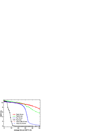
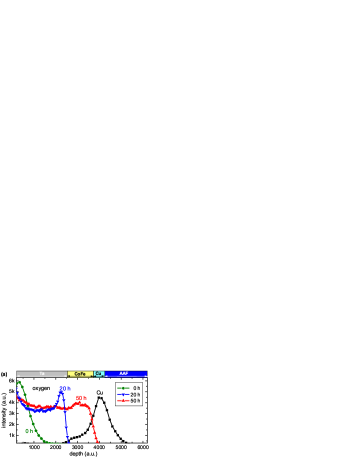
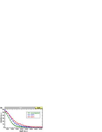
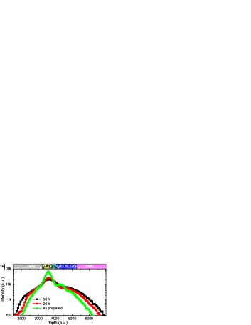
Fig. 1 shows the GMR effect of spin valves which differ only in the cap layer material as a function of the thermal stress time. The initial GMR effect differs slightly from sample to sample between 10.2 and 11.0 % due to intrinsic process variations. The change of GMR effect in the first 4 hours of thermal stress at 300 °C is very similar for all samples, but after 5 hours the stack with the 5 nm Ta cap shows a strong degradation which ends in a complete loss of GMR effect after 14 h. The stack with a Ta cap layer of double thickness (10 nm) undergoes the same fate, but only after 30 h. In contrast to the Ta capped stacks, the stacks with a 5 or 10 nm thick TaN cap layer do not show this sudden decrease in GMR, but a continuous decrease over time. Note that this observed decrease is acceptable for automotive applications.
A similar picture is observed for the change in stack resistance. The initial sheet resistance varies between 15.9 and 17.2 . After 8 h of storage at 300∘C the resistance of the stack with the 5 nm Ta cap increases sharply. This increase already decelerates after 12 h, but even after 50 h of storage no saturation is observed. The resistance increases to , which corresponds to an increase of more than 250 %. In contrast, the resistance changes for the other stacks are comparably small in the range of 5 % resp. 25 %.
Also shown in Fig. 1 are exponential decay fits to the curves of the 10 nm TaN and Ta capped stacks. While the decay in the case of the TaN cap layer can be described with one decay mode, for the Ta only cap layer, two decay modes fit better the experimental data. This is a first hint, that two different degradation mechanisms are at work in the GMR stacks.
To further investigate the origin of the degradation mechanisms which lead to the experimentally observed behavior, we performed SIMS experiments.
Fig. 2(a) shows the depth dependent oxygen intensities of a 10 nm Ta capped GMR stack after different annealing times. As a reference the copper signal is shown for an as-prepared sample. Within the whole figure, the corresponding layers of the GMR stack are shown above each individual panel. Because of different sputter rates for oxidized and non-oxidized Ta, we adjusted the depth for the samples with 20 h and 50 h of storage, by overlapping the copper peaks. This method is valid because the thickness of the layers and the copper peak distribution is unaffected by the oxidation.
Already the deposited stack comprises a small oxygen peak which is, however, clearly separated from the copper peak. The oxygen is only detectable in the Ta cap. After 20 h of storage the TaO layer has grown and the oxygen front reaches the CoFe free layer. At the same time the decay of the GMR effect is strongly accelerated (compare Fig. 1). In the next hours of storage the oxidation proceeds and after 50 h it reaches the Cu spacer layer. At this point only 0.2% of the original GMR effect is detectable.
A different picture is observed for the BSV with a 10 nm thick TaN cap (Fig. 2(b)). A distinctive intensity of oxygen signal is detected after sample preparation in the top of the cap, too, but the broadening of this signal is very slow. After 50 h of storage at 300∘C, the oxygen content in the area of the free layer is unchanged. Between 0 h and 50 h of storage, we observe a loss of GMR of 3% which cannot be attributed to the small increase of oxygen signal in the cap layer.
The data shown clearly identifies oxidation of the CoFe free layer as the first degradation mechanism leading to performance failure. The origin is the diffusion of oxygen through the cap layer. Our data also clearly shows, how a different choice of material for the cap layer (TaN) suppresses this mechanism effectively to an acceptable level for applications.
The continuous decrease of the GMR effect by annealing indicates that a second mechanism contributes to degradation. In Fig. 2(c) we also plotted the relative intensity of the cobalt signal in a logarithmic scale for a stack with a 5 nm thick TaN cap before storage and after 20h and 50h of storage. The highest cobalt intensity is detected in the area of the free layer; the two additional Co containing layers in the artificial antiferromagnet can be identified by the shoulders on the line of decreasing intensity towards higher depth in the case of the as prepared sample. With increased storage time the Co peaks broaden and the two CoFe layers in the AAF cannot be resolved anymore. Thus there is interdiffusion in the region of the functional layers of the GMR stack. Other components that are not shown in Fig. 2 also participate in this interdiffusion, e.g. Mn from the natural antiferromagnet layer which exhibits significant intensities in the region between the cap layer and the free layer after 50 h storage time. Thus, we have identified interdiffusion as a second source of degradation.
The most relevant functional layers within the GMR stack are the free layer (CoFe), the spacer (Cu), and the reference layer (CoFe). It is obvious that oxidation of these layers will immediately start to decrease and eventually destroy the GMR effect. The observed oxidation of the free layer results in a reduction of the spin-diffusion-length and the GMR effect first is reduced. When the complete free layer is oxidized, spin dependent scattering vanishes, and hence no GMR effect can be observed. By choice of a suitable cap layer material as TaN, the oxygen diffusion and oxidation mechanism is sufficiently suppressed.
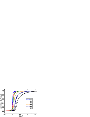
The second mechanism of degradation is not related to the oxygen. The continuous decrease of the GMR effect occurs similarly in all stacks independent on the choice of cap material or cap layer thickness. As can be concluded from the SIMS profiles, Co interdiffusion within the functional region occurs. The interdiffusion at the functional layers increases the resistance and surface roughness. Both effects contribute to a reduction of the GMR effect. The increased interface roughness also leads to a higher ferromagnetic Néel-coupling between the free and reference layer. In turn, this leads to a shift of the minor loop and the broadening of the hysteresis curve, as is observed for our devices after high-temperature storage (see Fig. 3) Neel:62 . Note, that due to the high activation energy of eV of this process the observed reduction in GMR by the interdiffusion effect is within the acceptable limits even for safety relevant applications in the automotive industry. A further improvement of the device performance could be obtained by tayloring diffusion barrier layers into the stack.
In summary, we have investigated the influence of the cap layer material and thickness on the thermal stability of bottom-pinned spin-valves. Oxygen diffusion through the cap layer reduces the GMR effect when the oxidation front reaches the CoFe free layer. This can be avoided effectively by using a TaN cap. A second diffusion mechanism leads to a continuous degradation of the GMR performance. Co interdiffusion results in a loss of Co in the functional core region and an increased orange-peel coupling. However, this detrimental effect occurs on a temperature and time scale which is not relevant for the required thermal stability of GMR devices in automotive applications.
This work was supported by the BMBF project 13N9084. The authors would like to thank Pascal Verrier, Jacques Liebault and coworkers of Altis Semicondutor, Corbeil Essonnes France, for the support in deposition and evaluation of the GMR wafers.
References
- (1) M. N. Baibich, J. M. Broto, A. Fert, F. Nguyen Van Dau, F. Petroff, P. Eitenne, G. Creuzet, A. Friederich, and J. Chazelas, Phys. Rev. Lett. 61, 2472 (1998).
- (2) G. Binasch, P. Grünberg, F. Saurenbach, and W. Zinn, Phys. Rev. B 39, 4828(R) (1989).
- (3) B. Dieny, V. S. Speriosu, S. Metin, S. S. P. Parkin, B. A. Gurney, P. Baumgart, and D. R. Wilhoit, J. Appl. Phys. 69, 4774 (1991).
- (4) J. Nogués and I. K. Schuller, J. Magn. Magn. Mater. 192, 203 (1999).
- (5) G. W. Anderson, Yiming Huai, and Mahendra Pakala, J. Appl. Phys. 87, 5726 (2000).
- (6) Young Keun Kim, Seong-Rae Lee, Se Ahn Song, Gyeong-Su Park, Hyuck Soo Yang, and K.-I. Min, J. Appl. Phys. 89, 6907 (2001).
- (7) Rong-Tan Huang, Fu-Rong Chen, Ji-Jung Kai, I-Fei Tsu, Sining Mao, and W. Kai, J. Appl. Phys. 89, 7625 (2001).
- (8) Ho Gun Cho, Young Keun Kim, and Seong-Rae Lee, J. Appl. Phys. 91, 8581 (2002).
- (9) Jong Soo Kim and Seong-Rae Lee, J. Appl. Phys. 99, 08R704 (2006).
- (10) M. Lederman, IEEE Trans. Magn. 35, 794 (1999).
- (11) L. Néel, Acad. Sci., Paris, C. R. 255, 1545 (1962); Acad. Sci., Paris, C. R. 255, 1676 (1962).