A method to study ageing of polydomain ferroelectrics using measurements of nonlinear permittivity
Abstract
It is known that the permittivity of the ferroelectric films is affected by several phenomena, which deteriorate the material quality (e.g. the redistribution of the crystal lattice defects, appearance of the electrode-adjacent non-ferroelectric layers or the spontaneous polarization screening due to a free charge injection across the electrode-adjacent layer, etc.). It is also known that the permittivity of ferroelectric polydomain films is controlled by the sum of two contributions: the crystal lattice (intrinsic) contribution and the domain wall movement (extrinsic) contribution. It is the latter one, which is very sensitive to the aforementioned phenomena and which plays a key role in the deterioration of the dielectric response of the ferroelectric polydomain films. In this Article, there is presented a method for the identification of the process, which is responsible for the ferroelectric ageing. The method is based on the analysis of the evolution of both the linear and nonlinear permittivity during ageing. Applicability of the method is theoretically demonstrated on four ageing scenarios in two qualitatively different systems where the evolution of the nonlinear permittivity is controlled, first, by a redistribution of the pinning centers on the domain wall and, second, by microstructural changes at the interface between the ferroelectric layer and the electrode. It is shown that each ageing scenario is characterized by unique trend in the evolution between the linear and nonlinear part of the permittivity, which can be verified experimentally.
pacs:
77.55.+f; 84.32.Tt; 77.80.DjI Introduction
Ferroelectric materials play more and more important role in many contemporary electronic devices. Due to the fundamental thermodynamic reasons, researchers and applied scientists integrating the ferroelectric materials into silicon-based semiconductor chips often face problems with a severe deterioration of the quality of the integrated ferroelectric films. These deterioration problems may manifest themselves during characterization experiments such as ferroelectric hysteresis loop measurements, pulse switching curve measurements, or small signal permittivity measurements, and cause phenomena called imprint, fatigue, ageing, etc. Unfortunately, determination of the “microstructural” mechanism predominantly responsible for an observed deteriorating effect in a particular ferroelectric sample is always very difficult, since several different microstructural mechanisms yield the similar manifestations in the aforementioned experiments. In order to get a better insight into microstructural mechanisms in ferroelectric samples, which would serve as a feedback for the optimization of the fabrication processes, a comprehensive analysis of the results of several characterization techniques should be performed.
The aforementioned issues have motivated the study presented in this work, where we analyze the possibility to use the measurements of nonlinear permittivity for the determination of mechanisms responsible for the ageing of polydomain ferroelectrics. The principle of our study is based on the fact that the dielectric response of the polydomain ferroelectric film is controlled by the sum of two contributions: the crystal lattice (intrinsic) contribution and the domain wall movement (extrinsic) contribution. Since the latter one is known to be sensitive to the geometry of the domain pattern and to several microstructural features of the material such as crystal lattice defects or free charges, which may work as pinning centers and may reduce the mobility of the domain walls, it is very likely that a comprehensive analysis of nonlinear dielectric permittivity may offer a simple and useful tool for getting some additional information about the microstructural processes responsible for the ferroelectric ageing.
The concept of the ferroelectric domain boundary contribution to permittivity has been discussed for the first time by Kittel in 1951 Kittel (1951). In the following decade, the existence of extrinsic contributions has been discussed several times in the literature, mainly in the context of Kittel’s theory on the resonance character of permittivity of polydomain ferroelectric in the microwave frequency region due to effective domain wall inertia Fatuzzo (1961); Stanford (1961). In 1960, Misařová Misařová (1960) made an early discovery of putting the existence of extrinsic contributions to permittivity in connection with ferroelectric ageing. Nevertheless, a definite answer was not given to the question of the magnitude of the extrinsic contribution with respect to the intrinsic one until the work by Fousek Fousek (1964) where the methodology of the experimental determination of the extrinsic and intrinsic contributions has been established in a sense understood today, i.e. the intrinsic contribution corresponds to the dielectric response of the poled single-domain sample and the extra enhancement in the dielectric response, which is measured on a polydomain sample, corresponds to the extrinsic contribution. After this breakthrough in understanding of the concept, the extrinsic contributions to permittivity, piezoelectric coefficients, and elastic compliance became the subject of an intense theoretical and experimental research Arlt et al. (1985); Robels and Arlt (1993); Xu et al. (2001); Taylor and Damjanovic (1997). Up to date, the extrinsic contributions have been considered something like a material curiosity of polydomain samples, which might be, however, beneficially used in applications. Nevertheless, the substantial drawback of the application of polydomain ferroelectric in electronic devices is the essential instability of the domain pattern, which is often manifested by a severe ageing of dielectric properties.
In this work, we present a method based on the comprehensive analysis of the evolution of the nonlinear dielectric response, which is caused by an evolution in the domain pattern microstructure. In Sec. II we analyze the intrinsic and extrinsic contributions to the nonlinear dielectric response of the ferroelectric polydomain film in detail. Section III presents a general method to identify the dominant microstructural phenomenon, which is responsible for the ageing of the ferroelectric. In Sec. IV we demonstrate the application of our method on two qualitatively different systems. First, the system where the extrinsic permittivity is controlled by the bending movements of pinned domain walls (Sec. IV.1) and, second, the system with electrode-adjacent passive layers (Sec. IV.2). We show that both systems under consideration may manifest several microstructurally different ageing scenarios, which are characterized by different features of the evolution of nonlinear permittivity.
II Nonlinear dielectric response of the polydomain ferroelectric
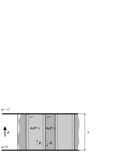
At first we analyze in detail the intrinsic and extrinsic contribution to the nonlinear dielectric response of the polydomain ferroelectric film, which is shown in Fig. 1. We consider a ferroelectric capacitor of thickness with the electric field applied to the material, which is split by 180∘ domain walls into the lamellar pattern of antiparallel domains at the two states with polarizations denoted by the symbols and . The volume fractions of the domains are denoted by the symbols and . In order to calculate the polarization response of the crystal lattice of the ferroelectric film, we adopt the incomplete thermodynamic potential (per unit volume of the sample) , which includes, first, the energy associated with the polarization of the crystal lattice , and, second, the subtracted work produced by external voltage sources . In order to present the basic principles of our method, we limit our considerations to the simplest case of the uniaxial ferroelectric with the vectors of the electric field and the polarization perpendicular to the top and bottom electrodes of the capacitor. A generalization to a more complicated system is more or less straightforward. For the simplification of the notation, we will omit the indices “” in the symbols for the vectors and in the following text. Then, the three lowest terms in the expansion of the function with respect to the polarization of the crystal lattice equals:
| (1) |
The polarization response of the crystal lattice can be found from the condition for the minimum of the thermodynamic potential :
| (2) |
In the ferroelectric phase, when and , the polarization response in the two stable polarization states of the crystal lattice in the adjacent domains can be expressed in a form of Taylor series with respect to the electric field :
| (3a) | |||||
| (3b) | |||||
where is the spontaneous polarization and is the dielectric susceptibility of the crystal lattice.
Now we can consider that the average polarization of the polydomain ferroelectric film is given by the volume weighted average of the polarization response in each domain state:
| (4) |
where . Substituting Eqs. (3) into Eq. (4), one gets:
| (5) |
It is convenient to express the above expression in terms of the net spontaneous polarization :
| (6) |
The function has a meaning of the extrinsic polarization response of the polydomain film to the electric field; i.e. the response, which is produced by the change in volume fractions of the two domain states due to the domain wall motions.
The response of the net spontaneous polarization to the electric field is controlled by nonlocal macroscopic phenomena, such as interaction of the domain walls with crystal lattice defects Tagantsev and Fousek (1999); Mokrý et al. (2007), depolarizing fields due to the presence of electrode-adjacent layers Kopal et al. (1999); Bratkovsky and Levanyuk (2001); Mokrý et al. (2004), reduction of the domain wall mobility due to free charges Mokrý et al. (2005, 2007), etc. In order to calculate the function we adopt the thermodynamic potential (per unit area of the ferroelectric capacitor) of the system with the constant electric field . The function includes two contributions: First, the free energy, which is increased when the domain wall is shifted from its equilibrium position (e.g. energy of the depolarizing field, surface energy of the domain walls, etc.), and, the subtracted work produced by the external sources that keeps the constant voltage on the electrodes (see Fig. 1). In the case of the non-poled (or depolarized) polydomain ferroelectric sample, the three lowest terms in the expansion of the function with respect to the net spontaneous polarization equal:
| (7) |
In the case of the stable domain pattern, when , the extrinsic polarization response is given by the condition for the minimum of the function :
| (8) |
and the net spontaneous polarization can be expressed in the form of the Taylor series with respect to the electric field :
| (9) |
where is the extrinsic contribution to dielectric susceptibility of the system and is the nonlinearity constant of the extrinsic contribution to dielectric susceptibility of the system with respect to the electric field.
Substituting Eq. (9) into Eq. (6) one gets the average nonlinear polarization response of the polydomain ferroelectric in the form:
| (10) |
where
| (11) |
is the nonlinearity constant due to the nonlinear dielectric response of the crystal lattice. It should be noted that the value of is also controlled by the linear extrinsic contribution to permittivity . Finally, the effective dielectric susceptibility of the polydomain ferroelectric layer is equal to:
| (12) |
III Method to study ageing of the polydomain ferroelectric
As it has already been mentioned, we consider that the extrinsic contribution to the nonlinear dielectric response is controlled by a particular nonlocal phenomenon associated with some microstructural mechanisms affecting the quality of the ferroelectric. It is reasonable to consider that in the systems with the pronounced ageing of ferroelectric properties, the associated microstructural mechanism should be also responsible for the evolution of the parameters and . Therefore, it is reasonable to expect that there exists a specific relation between the parameters and during ageing, which can be expressed in a form . The crucial point of the presented method is the fact, that the explicit form of the function is unique for the every particular microstructural mechanism of the dielectric ageing. Hence, when the experimentally observed dependence of vs. matches the theoretical prediction, there exists a reasonable indication that the considered mechanism is responsible for the observed ageing of the dielectric response. It means that this method can be used for the identification of the origin of the ageing of ferroelectric films. In this section, we show a general way to determine the characteristic function .
At first, we shall start with the fact that in the most of the ferroelectric materials with pronounced ageing of the dielectric properties, the dielectric nonlinearity is dominated by the contribution of the domain wall motion, i.e. . Then we consider that the evolution of the dielectric response is induced by the evolution in some “internal” microstructural parameter (e.g. average density of the pinning centers on the domain wall, average domain wall spacing, thickness of the electrode-adjacent dead layer, spontaneous polarization screening by free charges, etc.), which we denote by a general symbol . We consider that this parameter controls the values of and and we can write:
| (13a) | |||||
| (13b) | |||||
and hence
| (14) |
If the function is monotonic, we can express the parameter from Eq. (13b), i.e. and substitute it into Eq. (13a):
| (15) |
Now, if we consider that the intrinsic contribution to the dielectric susceptibility does not change in time, the function can be cross-checked by the analysis of the data extracted from the dielectric ageing measurements on the polydomain ferroelectric films. The first measured parameter is the small signal permittivity :
| (16) |
where is the relative permittivity of the crystal lattice. The second measured parameter is the dielectric nonlinearity constant , which can be determined from the following expression:
| (17) |
where is the electric field dependence of the permittivity of the polydomain ferroelectric film.
To apply our method on the experimental data, one should take two steps: first, to prove the quadratic dependence of the permittivity on the applied electric field given by Eq. (12) and, second, to identify the relationship between the small signal extrinsic permittivity and the dielectric nonlinearity parameter given by Eq. (17) during the dielectric ageing. Actually, verifying the first step represents the experimental evidence for a fast reversible movement of the domain walls, which should be distinguished from the Rayleigh-type relation, where the dielectric permittivity increases linearly with the ac-field as a result of the irreversible movement of domain walls under the sub-switching fields (usually a few tens of kV/cm) Taylor and Damjanovic (1998); Xu et al. (2001); Zhang and Lupascu (2006). In the second step, we can identify the particular ageing scenario from the experimental evidence of the mutual relationship between the parameters and in time during the dielectric ageing. By combining Eqs. (15) and (16) one gets
| (18) |
Therefore the validity of Eq. (18) can be demonstrated by the linear relationship between the values of and the total small field dielectric permittivity . The relationship given in Eq. (18) can be tested experimentally by fitting the values of and to the function of the form:
| (19) |
If the considered microstructural mechanism is responsible for the evolution of the dielectric response, the fitted value of the parameter should be approximately equal to unity, i.e. , and the fraction should correspond to the value of crystal lattice permittivity, i.e. , which can be checked by the measurements on the polarized single-domain sample.
IV Evolution of the nonlinear dielectric response during ageing
In this section, we demonstrate the applicability of the general method presented above for two particular systems. At first we present the system, where the extrinsic permittivity is controlled by bending movements of the pinned domain walls. Then we demonstrate the system with electrode-adjacent passive layers, where the domain wall movements are controlled by the depolarizing field in the electrode-adjacent passive layer.
IV.1 Ferroelectric ageing in the system with pinned domain walls
In this subsection, we adopt a model presented in Mokrý et al. (2007), where the extrinsic permittivity of the polydomain ferroelectric is controlled by bending movements of the pinned 180∘ domain walls. This scenario seems to be quite reasonable due to several direct observations of such interactions of the domain walls with bulk crystal lattice defects Yang et al. (1999). In addition, recent ab-initio calculations He and Vanderbilt (2003); Meyer and Vanderbilt (2002) have indicated that the oxygen vacancy, which is a very common defect in the perovskite ferroelectrics, has a smaller formation energy in the 180∘ domain wall than in the bulk and, thus, the oxygen vacancy accompanied with two free electrons to comply the requirement of the electroneutrality of the system can be responsible for the pinning effect on 180∘ domain walls.
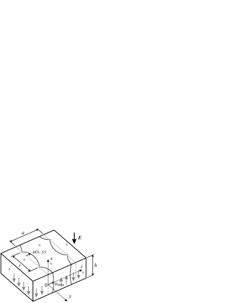
Figure 2 shows the model of bending movements of pinned 180∘ ferroelectric domain wall with the attached Cartesian coordinate system. We consider that the pinning centers on the domain wall are distributed in the and directions with an average distance between them and, thus, the pinning centers density on the domain wall is proportional to . When the electric field is applied to the ferroelectric film along the ferroelectric axis, the originally planar domain wall is bent between pinning centers, as indicated in Fig. 2, and the profile of the wall deflection is described by a function . The domain wall spacing is denoted by a symbol .
When the domain wall is bent, the thermodynamic function consists of two contributions: first, the surface energy of the bent domain wall and, second, the electrostatic energy associated with the depolarizing field due to discontinuous change of the normal component of the spontaneous polarization at the domain wall. At the constant electric field , the thermodynamic potential is given by the formula:
| (20) |
where the integrals are taken over the square where and are running from to , a symbol stands for the surface energy density associated with the surface tension of the bent domain wall, and a symbol stands for the electrostatic potential on the domain wall associated with the depolarizing field, which is produced by the bound charges of the surface density due to the discontinuous change of the normal component of the spontaneous polarization at the domain wall. The functions and are the partial derivatives of the function with respect to and , respectively. The function can be readily calculated by solving the Poisson equation for the electrostatic potential and by considering the conditions for the continuity of the normal component of the electric displacement and for the continuity of the electrostatic potential. If one considers that the net spontaneous polarization is equal to:
| (21) |
and that the maximum deflection of the domain wall is much smaller than the average distance between the pinning centers , our detailed calculations Mokrý et al. show that the leading terms in the Taylor expansion of the thermodynamic function in this particular system with respect to the net spontaneous polarization are:
| (22) |
where the symbol stands for the thickness of the domain wall. Solving Eq. (8) for this particular system, one gets:
| (23a) | |||||
| (23b) | |||||
Now in this particular system, we can distinguish two scenarios of the dielectric ageing.
IV.1.1 Dielectric ageing due to the progressive pinning
In this scenario, we consider, that due to the drift of the crystal lattice defects (e.g. oxygen vacancies) in the material, the concentration of the pinning centers on the domain wall may be increasing during the dielectric ageing. Therefore, in this scenario, which is characterized by a progressive pinning of the domain walls, we consider that the microstructural parameter responsible for the dielectric ageing is the average distance of the pinning centers and that the domain wall spacing remains constant.
Then we can express the parameter from Eq. (23b) and by substituting it into Eq. (23a) we arrive at the following form of the function :
| (24) |
In addition, from the time evolution of the parameters and we can estimate the evolution of the average distance between pinning centers on the domain wall:
| (25) |
IV.1.2 Dielectric ageing due to the domain wall coalescence
On the other hand, the same microstructural model offers a different ageing scenario. In the ferroelectric polydomain film, it is possible that the domain pattern is in the essentially non-equilibrium configuration and, therefore, there exists a “thermodynamic” force applied to the domain wall that drives the system to reach the “absolute” equilibrium configuration. In this situation, the depinning of some walls can occur and they can coalesce to reduce the energy proportional to the domain wall area. Then, we can consider that the parameter responsible for the evolution of the dielectric response is the domain spacing and that the concentration of the pinning centers on the domain wall remains constant during ageing. Hence, we can express the parameter from Eq. (23b) and by substituting it into Eq. (23a) we obtain the characteristic function in the form:
| (26) |
Similarly as in the previous ageing scenario, it is possible to estimate the time evolution of the average domain spacing from the time evolution of the parameters and :
| (27) |
Thus, it is seen that using cross-checking the two qualitatively different vs. dependences, it is possible to distinguish the microstructural processes, which are responsible for the evolution of the nonlinear dielectric response.
IV.2 Ferroelectric ageing in the system with the electrode-adjacent passive layer
In this subsection, we study the dielectric response of the system, where the ferroelectric layer with the antiparallel domain pattern is separated from the electrodes by the electrode-adjacent passive layers. Although the nature of these layers is not clear Sinnamon et al. (2001) and the direct observations of well-defined layers are rather scarce Hase et al. (1993), numerous indirect experimental observations support the wide acceptance of the passive layer concept. Until today, various mechanisms of film-electrode interactions have been proposed: creation of variable depletion layers associated with the Schottky barriers Dey et al. (1995); Basceri et al. (1997), low permittivity layers due to the oxygen vacancy entrapment at ferroelectric-electrode interfaces Lee et al. (1995), local suppression of polarization states in the near-electrode regions Vendik and Zubko (2000), local diffusion of the electrode material into the ferroelectric Stolichnov et al. (1999), or a chemically distinct surface phase Craciun and Singh (2000).
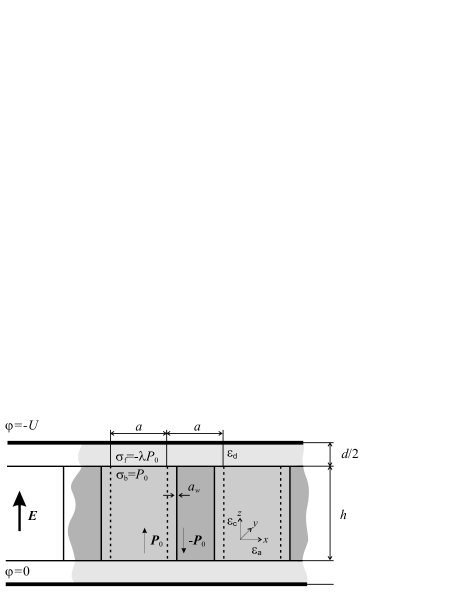
In order to calculate the dielectric response of the system with a passive layer, we adopt the model shown in Fig. 3. We consider a sandwich structure of the ferroelectric layer of the thickness with a lamellar antiparallel domain pattern, two dielectric passive layers of the total thickness and the permittivity , which separate the ferroelectric layer from the electrodes. The spontaneous polarization is considered to be constant within each domain and its abrupt change to zero at the interface of the ferroelectric and dielectric layers () leads to the appearance of a bound charge of the surface density . Due to finite conductivity of the passive layer, the bound charge is considered to be compensated by the free charge injected from the electrodes, so the proportionality factor called the degree of screening is introduced to measure the process of the charge transport , where .
In this model, we neglect the effect of the lattice pinning of the domain wall and we consider, for simplicity, that the net spontaneous polarization response to the electric field is controlled by the electrostatic energy of the depolarizing field produced by the periodic distribution of the bound and free charges at the interface of the ferroelectric and dead layers. In addition, we address in detail the case of the neutral domain pattern, i.e. we set in the absence of the applied voltage . The thermodynamic potential (per unit area of the sample) of a system with a given voltage on the electrodes and free charges inside the system, which includes the electrostatic energy of the electric field with the subtracted work produced by the external voltage sources, is given by the formula:
| (28) |
where is the area of the ferroelectric capacitor and is the surface density of free charges on the electrodes.
Calculation of the electrostatic energy requires the knowledge of the electrostatic potential , which satisfies the following equations of electrostatics in the ferroelectric and the passive layers,
| (29) |
with the boundary conditions at , and
| (30) |
where the subscripts and denote the ferroelectric and passive layer, respectively. Here is the sum of the surface density of the bound charge due to the spontaneous polarization and the free screening charge from the electrode. Solution of the potential and the calculation of the electrostatic energy for a similar model are already available in the literature Kopal et al. (1999); Bratkovsky and Levanyuk (2001); Mokrý et al. (2004), however with a different distribution of charges at the interface of the ferroelectric and passive layers. In this model, we consider that the spontaneous polarization continuously and smoothly changes its value within a distance representing the domain wall thickness. Then the function can be obtained in a form of the Fourier series:
| (31) |
In order to calculate the dielectric response, we express the function in terms of the applied electrode voltage and the net spontaneous polarization of the ferroelectric layer . With use of the results published earlier Kopal et al. (1999); Bratkovsky and Levanyuk (2001); Mokrý et al. (2004), the leading terms of the function in this model are equal to:
| (32) |
where
| (33a) | |||||
| (33b) | |||||
| (33c) | |||||
| and | |||||
| (33d) | |||||
Similarly as in the previous section also in this particular system we can distinguish two ageing scenarios:
IV.2.1 Dielectric ageing due to the thickening of the electrode-adjacent passive layer
It was reported Lee et al. (1995); Sun et al. (2002) that the fatigue of the dielectric response of the ferroelectric films can be caused by an increase of the thickness of the passive layer (e.g. due to the oxygen vacancy entrapment at the film-electrode interface). The main indication, from which such a statement is inferred, was the measurement of the size effect on the permittivity. There there was observed a decrease of the effective capacitance of the interface layer. Unfortunately, it was also demonstrated Mokrý et al. (2005) that the same effect on the permittivity, i.e. the effective decrease of the interface layer capacitance, can be produced by the spontaneous polarization screening by immobile charged defects. Nevertheless, by applying the present method on the data of the nonlinear permittivity, it was possible to distinguish whether such a fatigue scenario may take place.
In order to make it possible to use the principles of the discussed method to this particular situation, we should make following considerations: (i) The dominant phenomenon, which controls the extrinsic dielectric response, is the increase of the passive layer thickness, ; (ii) There is no spontaneous polarization screening, ; (iii) The domain pattern in the ferroelectric layer is dense, ; (iv) The passive layer in the system is thin compared to the average domain spacing, ; (v) The thickness of the domain wall is much smaller than the domain spacing, ; (vi) The permittivity of the passive layer can be approximated by the permittivity of the ferroelectric in the following way: ; Finally (vii), the average domain spacing remains constant during the dielectric ageing. Under these considerations, Eqs. (33) can be further simplified and Eq. (32) has a simple form:
| (34) |
Solving Eq. (8) for this particular situation, one gets:
| (35a) | |||||
| (35b) | |||||
Finally, the function is obtained by expressing the parameter from Eq. (35b) and by substituting it into Eq. (35a):
| (36) |
IV.2.2 Dielectric ageing due to the spontaneous polarization screening
Here we show that within the same microstructural model of the passive layer, we can discuss the possibility of a different ageing scenario. Due to the essentially semiconductive nature of ferroelectric materials and due to the strong experimental evidence Stolichnov and Tagantsev (1998); Tagantsev et al. (2001), the free charge injection across the electrode-adjacent layer has become a widely accepted concept. Nevertheless, it has been discussed mainly in connection with the ferroelectric switching measurements and the phenomenon called imprint, i.e. the horizontal shift of the hysteresis loop, which is caused by the internal bias field produced by the injected free charges. In this subsection, we deal with the free charge injection across the electrode-adjacent layer in the system with the polydomain ferroelectric layer.
It has been already reported Sun et al. (2002) that the pinning of domain walls in the electrode-adjacent region may represent a source of the essential nonlinearity of the dielectric response. It has been also reported Mokrý et al. (2005) that the similar pinning effect on the domain walls can be produced by the low mobility of the free charge at the film-electrode interface. Here we study how the injected free charges affect the nonlinear dielectric response of polydomain films.
In order to make a clear statement, whether the free charge injection across the passive layer can be responsible for the observed dielectric ageing using the presented method, we shall make the following considerations: (i) The dominant phenomenon, which controls the extrinsic dielectric response is the spontaneous polarization screening, ; (ii) The domain pattern in the ferroelectric layer is dense, ; (iii) The passive layer in the system is thin compared to the average domain spacing, ; (iv) The thickness of the domain wall is much smaller than the domain spacing, ; (v) The permittivity of the passive layer can be approximated by the permittivity of the ferroelectric in a following way, ; (vi) Since we are focused on the deteriorating impact of the free screening charges on the dielectric response of the polydomain ferroelectric film, which is produced due to the pinning effect of the free charges on the domain walls, we further consider that the free charges are of much lower mobility than the mobility of the domain wall in the absence of the free charges; Finally (vii), the average domain spacing remains constant during the dielectric ageing. Under these considerations, Eqs. (33) can be further simplified and Eq. (32) has a simple form:
| (37) |
where . Solving Eq. (8) for this particular situation, one gets:
| (38a) | |||||
| (38b) | |||||
It should be stressed again that the limit for approaching zero cannot be applied to Eqs. (38), since it violates the conditions for the applicability of our approximations. The reason for it can be described as follows. When the degree of screening is smaller than some critical value , the leading terms that control the thermodynamic function given by Eqs. (32) and (33) become very weakly controlled by the spontaneous polarization screening and the other parameters of the system have stronger effect on the net spontaneous response of the system. The critical value can be easily calculated by comparing the quadratic term coefficients in the expansion of the thermodynamic function with respect to the net spontaneous polarization in the two aforementioned different approximations given by Eqs. (34) and (37); this value reads: .
When we express the parameter from Eq. (38b) and when we substitute it into Eq. (38a), we obtain the characteristic function in the form:
| (39) |
In addition, it is possible to estimate the time evolution of the process of charge injection measured by the degree of screening from the time evolution of the parameters and :
| (40) |
However, it is seen that the thickness of the passive layer enters into the above equation and its value is always difficult to determine experimentally. Instead of that, we can use the expression for the effective capacitance per unite area of the ferroelectric-electrode interface , which can be estimated more easily.
V Discussion and conclusions
We have theoretically analyzed the nonlinear dielectric response of the ferroelectric polydomain film in two systems with different microstructural features: first, the system with the pinned domain walls and, second, the system with the electrode-adjacent passive layer. In these two considered systems, we studied four possible scenarios of the dielectric aging and found that there exists a clear qualitative difference in the evolution of the nonlinear dielectric response in each particular scenario. We found that the relation between the nonlinearity constant and the small signal permittivity expressed by the function , which is shown in Tab. V, is different in the each particular ageing scenario.
| Ageing scenario | |
| Progressive pinning by crystal lattice defects | |
| Domain wall coalescence | |
| Thickening of the electrode-adjacent layer | |
| Spontaneous polarization screening |
Therefore, the analysis of the experimentally observed evolution of the dielectric nonlinearity constant and the small signal permittivity can be used as a method to identify the microstructural mechanism, which plays the dominant role in the evolution of the nonlinear dielectric response.
To identify whether the particular microstructural mechanism is dominantly responsible for the dielectric ageing, the experimentally measured values of and should be fitted to the function of the general form:
| (41) |
If the considered mechanism controls the ageing, the fitted constant should approximately equal to unity and the constant should be equal to .
However, applicability of the presented method is subject to several considerations that should be kept in mind: (i) We consider that the intrinsic permittivity is time independent. (ii) We limit our analysis to the systems of uniaxial ferroelectric film with the 180∘ domain pattern and we neglect the effect of the non-180∘ domain walls on the dielectric response. (iii) We consider that the domain pattern in the ferroelectric is neutral, it means that the net spontaneous polarization is zero in the absence of the electric field. (iv) We consider that the nonlinear dielectric response is dominated by the domain wall movement and not by the dielectric response of the crystal lattice, . The first assumption is intuitive. To justify the second one, we need to point out that the extrinsic contribution to the nonlinear permittivity of the non-180∘ domain walls is negligible due to the elastic effects suppressing their mobility. The third assumption puts the restraints on the preparation of the ferroelectric samples, which should be depoled, e.g. using a fast decayed low frequency ac field. Finally, the last assumption should be checked for each ageing scenario and the particular configuration of the domain pattern microstructure using the fitted experimental values.
We believe that the presented method can by used as a simple and useful tool for getting a deeper insight into the configuration of the domain pattern and the quality of the ferroelectric thin films and for providing a way to identify the dominant microstructural phenomenon, which is responsible for the ageing of dielectric response of ferroelectric polydomain film.
Acknowledgements.
This project was supported by the Czech Science Foundation, Project No. GACR 202/06/0411. I would like to express my sincere gratitude to Professor Jan Fousek for his essential influence on my life, both personal and scientific. This work would not be possible without so much important experience of sharing his creative ideas, stimulating discussions with him, and without receiving his positive feedback. Thank you!References
- Kittel (1951) C. Kittel, Phys. Rev. 83, 458 (1951).
- Fatuzzo (1961) E. Fatuzzo, Journal of Applied Physics 32, 1571 (1961), URL http://link.aip.org/link/?JAP/32/1571/1.
- Stanford (1961) A. L. Stanford, Phys. Rev. 124, 408 (1961).
- Misařová (1960) A. Misařová, Sov. Phys.-Solid State 2, 1160 (1960).
- Fousek (1964) J. Fousek, Czechoslovak Journal of Physics 15, 412 (1964).
- Arlt et al. (1985) G. Arlt, D. Hennings, and G. de With, Journal of Applied Physics 58, 1619 (1985), URL http://link.aip.org/link/?JAP/58/1619/1.
- Robels and Arlt (1993) U. Robels and G. Arlt, Journal of Applied Physics 73, 3454 (1993), URL http://link.aip.org/link/?JAP/73/3454/1.
- Xu et al. (2001) F. Xu, S. Trolier-McKinstry, W. Ren, B. M. Xu, Z. L. Xie, and K. J. Hemker, Journal of Applied Physics 89, 1336 (2001), URL http://link.aip.org/link/?JAP/89/1336/1.
- Taylor and Damjanovic (1997) D. V. Taylor and D. Damjanovic, Journal of Applied Physics 82, 1973 (1997), URL http://link.aip.org/link/?JAP/82/1973/1.
- Tagantsev and Fousek (1999) A. Tagantsev and J. Fousek, Ferroelectrics 221, 193 (1999).
- Mokrý et al. (2007) P. Mokrý, Y. Wang, A. K. Tagantsev, and I. Stolichnov, in Sixteenth IEEE International Symposium on Applications of Ferroelectrics, 2007. (2007), pp. 336–339.
- Kopal et al. (1999) A. Kopal, P. Mokrý, J. Fousek, and T. Bahník, Ferroelectrics 223, 127 (1999).
- Bratkovsky and Levanyuk (2001) A. M. Bratkovsky and A. P. Levanyuk, Phys. Rev. B 63, 132103 (2001).
- Mokrý et al. (2004) P. Mokrý, A. K. Tagantsev, and N. Setter, Phys. Rev. B 70, 172107 (2004).
- Mokrý et al. (2005) P. Mokrý, A. Tagantsev, and N. Setter, Ferroelectrics 319, 435 (2005).
- Mokrý et al. (2007) P. Mokrý, A. K. Tagantsev, and J. Fousek, Physical Review B (Condensed Matter and Materials Physics) 75, 094110 (pages 6) (2007), URL http://link.aps.org/abstract/PRB/v75/e094110.
- Taylor and Damjanovic (1998) D. V. Taylor and D. Damjanovic, Applied Physics Letters 73, 2045 (1998), URL http://link.aip.org/link/?APL/73/2045/1.
- Zhang and Lupascu (2006) Y. Zhang and D. C. Lupascu, Journal of Applied Physics 100, 054109 (pages 8) (2006).
- Yang et al. (1999) T. J. Yang, V. Gopalan, P. J. Swart, and U. Mohideen, Phys. Rev. Lett. 82, 4106 (1999).
- He and Vanderbilt (2003) L. He and D. Vanderbilt, Phys. Rev. B 68, 134103 (2003).
- Meyer and Vanderbilt (2002) B. Meyer and D. Vanderbilt, Phys. Rev. B 65, 104111 (2002).
- (22) P. Mokrý, Y. Wang, A. K. Tagantsev, and I. Stolichnov, (to be published).
- Sinnamon et al. (2001) L. J. Sinnamon, R. M. Bowman, and J. M. Gregg, Applied Physics Letters 78, 1724 (2001), URL http://link.aip.org/link/?APL/78/1724/1.
- Hase et al. (1993) T. Hase, T. Sakuma, Y. Miyasaka, K. Hirata, and N. Hosokawa, Japanese Journal of Applied Physics 32, 4061 (1993).
- Dey et al. (1995) S. K. Dey, J. J. Lee, and P. Alluri, Japanese Journal of Applied Physics 34, 3142 (1995).
- Basceri et al. (1997) C. Basceri, S. K. Streiffer, A. I. Kingon, and R. Waser, Journal of Applied Physics 82, 2497 (1997), URL http://link.aip.org/link/?JAP/82/2497/1.
- Lee et al. (1995) J. J. Lee, C. L. Thio, and S. B. Desu, Journal of Applied Physics 78, 5073 (1995), URL http://link.aip.org/link/?JAP/78/5073/1.
- Vendik and Zubko (2000) O. G. Vendik and S. P. Zubko, Journal of Applied Physics 88, 5343 (2000), URL http://link.aip.org/link/?JAP/88/5343/1.
- Stolichnov et al. (1999) I. Stolichnov, A. K. Tagantsev, N. Setter, J. S. Cross, and M. Tsukada, Applied Physics Letters 75, 1790 (1999), URL http://link.aip.org/link/?APL/75/1790/1.
- Craciun and Singh (2000) V. Craciun and R. K. Singh, Applied Physics Letters 76, 1932 (2000), URL http://link.aip.org/link/?APL/76/1932/1.
- Sun et al. (2002) J. L. Sun, J. Chen, X. J. Meng, J. Yu, L. X. Bo, S. L. Guo, and J. H. Chu, Applied Physics Letters 80, 3584 (2002), URL http://link.aip.org/link/?APL/80/3584/1.
- Stolichnov and Tagantsev (1998) I. Stolichnov and A. K. Tagantsev, Journal of Applied Physics 84, 3216 (1998), URL http://link.aip.org/link/?JAP/84/3216/1.
- Tagantsev et al. (2001) A. K. Tagantsev, I. Stolichnov, E. L. Colla, and N. Setter, Journal of Applied Physics 90, 1387 (2001), URL http://link.aip.org/link/?JAP/90/1387/1.