Critical current of spin transfer torque-driven magnetization dynamics in magnetic multilayers
Abstract
The critical current of the spin transfer torque-driven magnetization dynamics was studied by taking into account both spin pumping and the finite penetration depth of the transverse spin current. We successfully reproduced the recent experimental results obtained by Chen et al. [Phys. Rev. B 74, 144408 (2006)] and found that the critical current remains finite even in the zero-thickness limit of the free layer. We showed that the remaining value of the critical current is determined mainly by spin pumping. We also showed that we could control the critical current by varying the spin diffusion length of the nonmagnetic electrode adjacent to the free layer.
pacs:
72.25.Ba, 73.23.-b, 75.70.Cn, 76.60.EsSpin transfer torque (STT) is the torque due to the transfer of transverse spin angular momentum from the conducting electrons to the magnetization of a ferromagnet Slonczewski (1996); Berger (1996). The STT in magnetic multilayers such as the current perpendicular-to-the-plane giant magneto-resistive (CPP-GMR) Katine et al. (2000); Carva et al. (2006); Haney et al. (2007) and tunnel magneto-reisistive (TMR) Heiliger and Stiles (2008); Kubota et al. (2008); Sankey et al. (2008) spin valves has been investigated intensively because STT-driven magnetization dynamics is a promising technique to operate the spin-electronics devices such as magnetic random access memories and microwave oscillators. One of the main obstacles in developing STT-based spin-electronics devices is the high critical current density. The critical current density required to induce the STT driven magnetization dynamics in CPP-GMR spin valves is as high as A/cm2 Kiselev et al. (2003); Seki et al. (2006); Deac et al. (2006); Chen et al. (2006).
On the other hand, the CPP-GMR spin-valve is one of the promising candidates for the read head for ultra-high-density magnetic recording Tanaka et al. (2002); Takagishi et al. (2002). It is known that STT-driven magnetization dynamics produces noise, and that low critical current density is required for the read head applicationZhu and Zhu (2004). Therefore, it is natural to ask how to control the critical current density of STT-driven magnetization dynamics in CPP-GMR spin valves.
STT was first proposed by Slonczewski Slonczewski (1996) and independently by Berger Berger (1996) in 1996. In Slonczewski’s theory the critical current of STT-driven magnetization dynamics is expressed as Grollier et al. (2003); Morise and Nakamura (2005),
| (1) |
where is the elementary charge and is the Dirac constant. , , , and are the magnetization, cross-section area, thickness, gyromagnetic ratio and intrinsic Gilbert damping constant of the free layer, respectively. is the angular frequency of the magnetization around the equilibrium point. The transverse spin polarization coefficient depends only on the relative angle of the magnetizations of the fixed and free layers Slonczewski (1996); Grollier et al. (2003). According to Slonczewski’s theory, we can control the critical current by varying the thickness of the free layer, and the critical current vanishes in the limit of .
However, recently, Chen et al. Chen et al. (2006) reported that the critical current of STT-driven magnetization dynamics of a CPP-GMR spin valve remains finite even in the zero-thickness limit of the free layer. What are missing from the above consideration based on Slonczewski’s theory are the effects of the finite penetration depth of the transverse spin current, , Zhang et al. (2002, 2004); Taniguchi et al. (2008) and spin pumping Taniguchi et al. (2008); Mizukami et al. (2002a, b); Tserkovnyak et al. (2002, 2003). The penetration depth of the transverse spin current is the characteristic length of the ferromagnetic metal over which the transfer of the spin angular momentum from conducting electrons to the magnetization is achieved. If the free layer is thinner than , the conducting electrons cannot transfer their angular momentum to the magnetization to exert STT. Spin pumping is the phenomenon by which the spin current is pumped out from the free layer into the other layers. The magnetic (Gilbert) damping of the free layer is enhanced by spin pumping. Therefore, we need to analyze the experimental results by taking into account both the finite penetration depth of the transverse spin current and spin pumping to understand the mechanism that determines the critical current of STT-driven magnetization dynamics in magnetic multilayers.
In this paper, we study the critical current of STT-driven magnetization dynamics by taking into account both the finite penetration depth of the transverse spin current and spin pumping. In order to analyze the experiments by Chen et al. Chen et al. (2006), we extend the spin pumping theory with the finite penetration depth Taniguchi et al. (2008) to include the electric current. We show that the critical current remains finite even in the zero-thickness limit of the free layer, which agrees quantitatively well with the results of Ref. Chen et al. (2006), and that the remaining value is determined mainly by spin pumping. We find that we can control the remaining value of the critical current by varying the spin diffusion length of the nonmagnetic electrode adjacent to the free layer. The longer the spin diffusion length of the nonmagnetic electrode, the smaller the remaining value of the critical current.
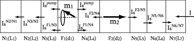
The system we consider is shown in Fig. 1. Two ferromagnetic layers (F1 and F2) are sandwiched by the nonmagnetic layers Ni . The F1 and F2 layers correspond to the free and fixed layer, respectively. is the unit vector pointing the direction of the magnetization of the Fk layer. and are the thicknesses of the Fk and Ni layers, respectively. The electric current flows from the N7 layer to the N1 layer.
In order to analyze the STT-driven magnetization dynamics in the multilayer system shown in Fig. 1, we extend the spin-pumping theory with the finite penetration depth Taniguchi et al. (2008) to include the electric current. The electric current and pumped spin current at the Fk/Ni interface (into Ni) are derived by the circuit theory Brataas et al. (2001), and expressed in terms of the charge accumulation and the spin accumulation as Tserkovnyak et al. (2002); Brataas et al. (2001)
| (2) | |||
| (3) |
where is the Planck constant, is the sum of the spin-up and spin-down conductances, is the spin polarization of the conductances and is the real (imaginary) part of the mixing conductance. The spin current at each Fk/Ni and Ni/Nj interface (into Ni) are given by Taniguchi et al. (2008); Brataas et al. (2001)
| (4) | |||
| (5) |
where is the real (imaginary) part of the transmission mixing conductance at the Fk/Ni interface and is the conductance of the one spin channel at the interface. The spin current of Eq. (4) is obtained from the circuit theory of Brataas et al. Brataas et al. (2001) eliminating the assumption that the non-equilibrium distribution function of the electrons in a ferromagnetic layer is aligned to the direction of the magnetization in spin space. It should be noted that the transmission mixing conductance in Eq. (4) is different from that defined by Zwierzycki et al. Zwierzycki et al. (2005). Zwierzycki et al. calculated a transmission mixing conductance defined through a N/F/N junction defined as where and is the tranmission coefficient for electrons from F (N) to N (F), and showed that depends on the thickness of the ferromagnetic layer due to the phase factor Zwierzycki et al. (2005). On the other hand, the transmission mixing conductance in Eq. (4) is defined by , and independent of the thickness of the ferromagnetic layer. Although the original formulation of the circuit theory assumed the spatially uniform charge and spin accumulation Brataas et al. (2001), it has been shown that the circuit theory is applicable to the diffusive system Tserkovnyak et al. (2003); Bauer et al. (2003). It should be noted that there is a controversial issue regarding the transverse spin accumulation in the ferromagnetic layer, Zhang et al. (2002, 2004); Tserkovnyak et al. (2002, 2003); Brataas et al. (2001); Slonczewski (2006); Urazhdin et al. (2005); Guo and Jalil (2005).
The spin accumulation in the nonmagnetic layer, obeys the diffusion equation Valet and Fert (1993), and is expressed as a linear combination of , where is the spin diffusion length of the nonmagnetic layer. The spin current in the nonmagnetic layer is given by
| (6) |
where is the conductivity of the nonmagnetic layer.
The longitudinal spin accumulation in the ferromagnetic layer, , also satisfies the diffusion equation, and is expressed as a linear combination of , where is the longitudinal spin diffusion length of the ferromagnetic layer Valet and Fert (1993). The longitudinal spin current in the ferromagnetic layer is
| (7) |
where and are the electro-chemical potential and the conductivity for the spin-up (spin-down) electrons, respectively. The spin polarization of the conductivity is defined as .
The transverse spin accumulation in the ferromagnetic layer obeys Zhang et al. (2002)
| (8) |
where and is the transverse spin diffusion length. is the strength of the exchange field Zhang et al. (2004) and is the diffusion constant of spin-up (spin-down) electrons. The spin polarization of the diffusion constant is defined as . The transverse spin accumulation is expressed as a linear combination of and , where . The penetration depth of the transverse spin current is defined as Taniguchi et al. (2008). The transverse spin current in the ferromagnetic layer is expressed as
| (9) |
The total spin currents across the N3/F1 and F1/N4 interfaces, i.e., and , exert the torque on the magnetization . In order to obtain the spin current , we solve the diffusion equations of spin accumulations in each layer. The boundary conditions are as follows. We assume that the thickness of the N1 and N7 layer, and , are sufficiently thick enough compared to their spin diffusion length, and that the spin current is zero at the outer boundary of the N1 and N7 layer. We also assume that the spin current is continuous at all Fk/Ni and Ni/Nj interfaces and that the electric current is constant through the entire structure. The spin current is obtained as a function of the electric current and the pumped spin current .
The torque modifies the Landau-Lifshitz-Gilbert (LLG) equation of the magnetization . The LLG equation conserves the magnitude of the magnetization, and thus the vectors and are perpendicular to the magnetization . Since the torque is perpendicular to the torque can be decomposed into the directions of and . The LLG equation of is expressed as Tserkovnyak et al. (2002); Taniguchi et al. (2008); Taniguchi and Imamura (2007)
| (10) |
where is the effective magnetic field. represents the enhancement of the Gilbert damping constant. The enhancement is proportional to the electric current and independent of the pumped spin current . The enhancement represents the contribution from the pumped spin current and is independent of the electric current. It should be noted that the enhancement differs from the result of the conventional spin-pumping theory Tserkovnyak et al. (2003) because is a function of . The enhancement of the gyromagnetic ratio is also a function of the electric current and the pumped spin current.
Let us move to the analysis of experimental results of Ref. Chen et al. (2006). In general, the dynamics of the magnetization determined by Eq. (10) is very complicated; thus, we cannot obtain the analytical expression of the critical current of STT-driven magnetization dynamics of the magnetization . However, in the experiment of Ref. Chen et al. (2006), the system, and therefore the dynamics of , have axial symmetry along the direction normal to the film plane because the high magnetic field (about 7 T) is applied along this direction. Then we assume that the magnetization of the F1 layer precesses around the magnetization of the F2 layer with the relative angle and the angular frequency . The critical current of STT-driven magnetization dynamics is defined by the current that satisfies the condition, . The critical current is expressed as
| (11) |
where is the effective transverse spin polarization coefficient that is determined by the diffusion equations of the spin accumulations, and thus the coefficient is the function of and .
The parameters we used are as follows. The system consists of nine layers shown in Fig. 1, where F1 and F2 are Co, N1, N3, N4, N5 and N7 are Cu, and N2 and N6 are Pt. The thicknesses of the N3, N4 and N5 layers are 10 nm, the thicknesses of the N2 and N6 layers are 3 nm and the thickness of the F2 layer is 12 nm Chen et al. (2006). The thickness of the N1 and N7 layers are taken to be 10 m, which is sufficiently longer than the spin diffusion length. The resistivity of Cu and Pt are 14 and 42 nm, respectively Bass and Jr (2007). The spin diffusion length of Cu and Pt are 1000 and 14 nm, respectively Bass and Jr (2007). The conductance at the Cu/Pt interface is 35 nm-2 Bass and Jr (2007). The magnetization , the intrinsic Gilbert damping constant and the gyromagnetic ratio of Co are 0.14 T, 0.008 and Hz/T, respectively Chen et al. (2006); Beaujour et al. (2006). For simplicity, we assume that ===0.46 for Co Bass and Jr (2007). The resistivity and the longitudinal spin diffusion length of the Co are 60 nm and 40 nm, respectively Bass and Jr (2007). The transverse spin diffusion length is Zhang et al. (2002). is taken to be 3.0 nm Zhang et al. (2004), i.e., nm. The conductances at the Co/Cu interface, , and , are 50, 27 and 0.4 nm-2, respectively Tserkovnyak et al. (2002, 2003); Brataas et al. (2001); Zwierzycki et al. (2005); Xia et al. (2002). The angular frequency is where the strength of the applied magnetic field is 7 T Chen et al. (2006). The relative angle of the two magnetizations is assumed to be Chen et al. (2006). Although there are many material parameters in our calculation these values except are determined by the experiments and ab initio calculations. The value of is determied by fitting, and taken to be 6.0 nm-2. According to Ref. Chen et al. (2006), the experimental values are the low temperature values.
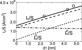
The obtained critical current density is plotted by a solid line against the thickness of the free layer in Fig. 2. The experimental results of Ref. Chen et al. (2006) are shown by open circles. One can see that our results agree well with the experimental results. The critical current density decreases as the thickness of the free layer decreases, and remains finite even in the zero-thickness limit of the free layer. In order to see the main mechanism that determines the remaining value of the critical current density, we decompose of Eq. (11) into two parts as , where is the component proportional to and is the component proportional to . In Fig. 2, the components and are plotted by dotted and dot-dashed lines, respectively. As shown in Fig. 2 the remaining value of the critical current in the limit of is determined mainly by the spin pumping. Although is also finite in the limit of because of the finite penetration depth of the transverse spin current in the F1 layer, the remaining value is small compared to . The dashed line in Fig. 2 is the calculated critical current in the limit of . According to Fig. 2 we conclude that the effect of the finite penetration depth is less important to describe the results of Ref. Chen et al. (2006).
The reason why both and remain finite in the limit of is understood as follows. Slonczewski assumed that the transverse spin current injected into the free layer is absorbed at the interface, and thus, STT is independent of the thickness of the free layer. The critical current is determined by the competition between STT and the magnetic (Gilbert) damping of the free layer. The spin relaxation due to the Gilbert damping is proportional to the thickness of the free layer , and thus, the critical current given by Eq. (1) is proportional to and vanishes in the limit of . If the penetration depth of the transverse spin current is finite, the transverse spin current is not fully absorbed in the free layer in the case of . Then the strength of STT is decreased compared to the prediction of Slonczewski Slonczewski (1996), and thus, the critical current is increased. Spin pumping enhances the Gilbert damping, and the spin relaxation due to spin pumping is independent of the thickness of the free layer. Thus, remains finite in the limit of .
The dependences of the remaining value, about A/cm2, on the parameters given above are as follows. If the resistivity and the longitudinal spin diffusion length of Co are taken to be 210 nm and 38 nm, respectively, which are the room temperature values Bass and Jr (2007), the remaining value is estimated to be A/cm2. The reduction the longitudinal spin diffusion length decreases the penetration depth , and thus, the remaining value is reduced. The values of conductances, and , include the effect of the Sharvin conductace Zwierzycki et al. (2005). If , and are taken to be 19.3, 14.6 and -1.1 nm-2, respectively, which are the bare values estimated by ab initio calculation Zwierzycki et al. (2005), the remaining value is estimated to be A/cm2. The reduction of the mixing conductance decreases the effect of spin pumping Tserkovnyak et al. (2002), and thus, the remaining value is reduced. If the transmission mixing conductance is taken to be 3.0 (12.0) nm-2, which is half (twice) compared to the value used in Fig. 2, the remaining value is estimated to be A/cm2. The reduction (enhancement) of the transmission mixing conductance decreases (increases) the effect of the transverse spin accumulation, or equivallently the penetration depth, on the spin current given by Eq. (4), and thus, the remaining value is reduced (enhanced). We conclude that although there are many material parameters in our calculation the parameter dependence of the remaining value is small, and our calculation gives the correct order of the critical current.
The above results imply that we can increase or decrease the critical current by controlling the spin pumping. Spin pumping is the phenomenon by which the precessing magnetization of the free layer pumps spin current into the other layers. The other layers act as an additional spin sink and the magnetic damping of the free layer is enhanced by spin pumping. The ability of the spin sink is determined by the spin diffusion length since the spin diffusion length is inversely proportional to the square root of the spin scattering rate. Materials with short (long) spin diffusion length act as a good (bad) spin sink. One may expect that if the nonmagnetic layer adjacent to the free layer is made of material with a long spin diffusion length, the Gilbert damping constant and therefore the critical current is suppressed. In the limit of infinite spin diffusion length, , there is no spin flip scattering in the nonmagnetic layer and the spin pumping into the nonmagnetic layer is forbidden. On the other hand, if the nonmagnetic layer adjacent to the free layer is made of a material with a short spin diffusion length, the Gilbert damping constant and the critical current is enhanced. In the limit of , the pumped spin current is absorbed at the interface and enhancement of the critical current due to spin current is maximized.
In order to verify the above statement, we analyzed the critical current of the five-layer system, N1/F1/N4/F2/N7 (see Fig. 1), where all parameters except the spin diffusion length of the N1 layer, , are the same as those used in the analysis of Chen’s experiment. In Fig. 3, we plot the critical current in the zero-thickness limit of the free layer as a function of the spin diffusion length of the N1 layer . One can see that the critical current is a decreasing function of . The critical current remains finite in the limit of because of the spin pumping into the N4 layer and the finite penetration depth of the transverse spin current. The result shown in Fig. 3 shows that we can control the critical current by varying the spin diffusion length of the nonmagnetic electrode adjacent to the free layer.

We cannot apply the present formula directly to a magnetic tunnel junction (MTJ) because spin accumulation is not well-defined in an insulator (I). Although the spin pumping across the insulating barrier is beyond the scope of this paper, the spin pumping into the metallic electrode should give the finite remaining value of the critical current. Recently spin pumping in a magnetic tunnel junction (MTJ) was studied by Moriyama et al. Moriyama et al. (2008). They studied a ferromagnetic resonance in Al/AlO/Ni80Fe20/Cu MTJ, and found the generation of the voltage on the order of few V, which is qualitatively explained by the theory of spin pumping in a metallic structure Wang et al. (2006), but requires unreasonably large value of mixing conductance. The results of Moriyama et al. suggest that a new non-equilibtirum phenomena exists in MTJ, e.g. charge pumping or the development of the longitudinal spin accumulation in a ferromagnetic layer Tserkovnyak et al. (2008).
In conclusion, we studied the critical current of spin transfer torque-driven magnetization dynamics by taking into account both the finite penetration depth of the transverse spin current in the ferromagnetic layer and spin pumping. We extend the spin-pumping theory with the finite penetration depth to include the electric current and successfully reproduced the experimental results of Ref. Chen et al. (2006). We showed that the critical current remains finite in the zero-thickness limit of the free layer and the remaining value is determined mainly by spin pumping. We also showed we can control the remaining value of the critical current by varying the spin diffusion length of the nonmagnetic electrode adjacent to the free layer.
The authors would like to thank W. Chen, A. D. Kent and their co-workers for providing their experimental results. This work was supported by JSPS and NEDO.
References
- Slonczewski (1996) J. C. Slonczewski, J. Magn. Magn. Mater. 159, L1 (1996).
- Berger (1996) L. Berger, Phys. Rev. B 54, 9353 (1996).
- Katine et al. (2000) J. A. Katine, F. J. Albert, R. A. Buhrman, E. B. Myers, and D. C. Ralph, Phys. Rev. Lett. 84, 3149 (2000).
- Carva et al. (2006) K. Carva, I. Turek, J. Kudrnovský, and O. Bengone, Phys. Rev. B 73, 144421 (2006).
- Haney et al. (2007) P. M. Haney, D. Waldron, R. A. Duine, A. S. Núnez, H. Guo, and A. H. MacDonald, Phys. Rev. B 76, 024404 (2007).
- Heiliger and Stiles (2008) C. Heiliger and M. D. Stiles, Phys. Rev. Lett. 100, 186805 (2008).
- Kubota et al. (2008) H. Kubota, A. Fukushima, K. Yakushiji, T. Nagahama, S. Yuasa, K. Ando, H. Maehara, Y. Nagamine, K. Tsunekawa, D. D. Djayaprawira, et al., Nature Phys. 4, 37 (2008).
- Sankey et al. (2008) J. C. Sankey, Y.-T. Cui, J. Z. Sun, J. C. Slonczewski, R. A. Buhrman, and D. C. Ralph, Nature Phys. 4, 67 (2008).
- Kiselev et al. (2003) S. I. Kiselev, J. C. Sankey, I. N. Krivorotov, N. C. Emley, R. J. Schoelkopf, R. A. Buhrman, and D. C. Ralph, Nature 425, 380 (2003).
- Seki et al. (2006) T. Seki, S. Mitani, K. Yakushiji, and K. Takanashi, Appl. Phys. Lett. 89, 172504 (2006).
- Deac et al. (2006) A. Deac, K. J. Lee, Y. Liu, O. Redon, M. Li, P. Wang, J. P. Noziéres, and B. Dieny, Phys. Rev. B 73, 064414 (2006).
- Chen et al. (2006) W. Chen, M. J. Rooks, N. Ruiz, J. Z. Sun, and A. D. Kent, Phys. Rev. B 74, 144408 (2006).
- Tanaka et al. (2002) A. Tanaka, Y. Shimizu, Y. Seyama, K. Nagasaka, R. Kondo, H. Oshima, S. Eguchi, and H. Kanai, IEEE Trans. Magn. 38, 84 (2002).
- Takagishi et al. (2002) M. Takagishi, K. Koi, M. Yoshikawa, T. Funayama, H. Iwasaki, and M. Sahashi, IEEE Trans. Magn. 38, 2277 (2002).
- Zhu and Zhu (2004) J.-G. Zhu and X. Zhu, IEEE Trans. Magn. 40, 182 (2004).
- Grollier et al. (2003) J. Grollier, V. Cros, H. Jaffrés, A. Hamzic, J. M. George, G. Faini, J. B. Youssef, H. LeGall, and A. Fert, Phys. Rev. B 67, 174402 (2003).
- Morise and Nakamura (2005) H. Morise and S. Nakamura, Phys. Rev. B 71, 014439 (2005).
- Zhang et al. (2002) S. Zhang, P. M. Levy, and A. Fert, Phys. Rev. Lett. 88, 236601 (2002).
- Zhang et al. (2004) J. Zhang, P. M. Levy, S. Zhang, and V. Antropov, Phys. Rev. Lett. 93, 256602 (2004).
- Taniguchi et al. (2008) T. Taniguchi, S. Yakata, H. Imamura, and Y. Ando, Appl. Phys. Express 1, 031302 (2008).
- Mizukami et al. (2002a) S. Mizukami, Y. Ando, and T. Miyazaki, J. Magn. Magn. Mater. 239, 42 (2002a).
- Mizukami et al. (2002b) S. Mizukami, Y. Ando, and T. Miyazaki, Phys. Rev. B 66, 104413 (2002b).
- Tserkovnyak et al. (2002) Y. Tserkovnyak, A. Brataas, and G. E. W. Bauer, Phys. Rev. B 66, 224403 (2002).
- Tserkovnyak et al. (2003) Y. Tserkovnyak, A. Brataas, and G. E. W. Bauer, Phys. Rev. B 67, 140404(R) (2003).
- Brataas et al. (2001) A. Brataas, Y. V. Nazarov, and G. E. W. Bauer, Eur. Phys. J. B 22, 99 (2001).
- Zwierzycki et al. (2005) M. Zwierzycki, Y. Tserkovnyak, P. J. Kelly, A. Brataas, and G. E. W. Bauer, Phys. Rev. B 71, 064420 (2005).
- Bauer et al. (2003) G. E. W. Bauer, Y. Tserkovnyak, D. Huertas-Hernando, and A. Brataas, Phys. Rev. B 67, 094421 (2003).
- Slonczewski (2006) J. C. Slonczewski, Phys. Rev. Lett. 96, 019707 (2006).
- Urazhdin et al. (2005) S. Urazhdin, R. Loloee, and W. P. Pratt, Phys. Rev. B 71, 100401(R) (2005).
- Guo and Jalil (2005) J. Guo and M. B. A. Jalil, Phys. Rev. B 71, 224408 (2005).
- Valet and Fert (1993) T. Valet and A. Fert, Phys.Rev.B 48, 7099 (1993).
- Taniguchi and Imamura (2007) T. Taniguchi and H. Imamura, Phys. Rev. B 76, 092402 (2007).
- Bass and Jr (2007) J. Bass and W. P. P. Jr, J. Phys.: Condens. Matter 19, 183201 (2007).
- Beaujour et al. (2006) J.-M. L. Beaujour, W. Chen, A. D. Kent, and J. Z. Sun, J. Appl. Phys. 99, 08N503 (2006).
- Xia et al. (2002) K. Xia, P. J. Kelly, G. E. W. Bauer, A. Brataas, and I. Turek, Phys. Rev. B 65, 220401(R) (2002).
- Moriyama et al. (2008) T. Moriyama, R. Cao, X. Fan, G. Xuan, B. K. Nikolić, Y. Tserkovnyak, J. Kolodzey, and J. Q. Xiao, Phys. Rev. Lett. 100, 067602 (2008).
- Wang et al. (2006) X. Wang, G. E. W. Bauer, B. J. van Wees, A. Brataas, and Y. Tserkovnyak, Phys. Rev. Lett. 97, 216602 (2006).
- Tserkovnyak et al. (2008) Y. Tserkovnyak, T. Moriyama, and J. Q. Xiao, Phys. Rev. B 78, 020401(R) (2008).