Correlation between structure and conductivity of stretched Nafion.
Abstract
We have used coarse-grained simulation methods to investigate the effect of stretching-induced structure orientation on the proton conductivity of Nafion-like polyelectrolyte membranes. Recent experimental data on the morphology of ionomers describe Nafion as an aggregation of polymeric backbone chains forming elongated objects embedded in a continuous ionic medium. Uniaxial stretching of a recast Nafion film causes a preferential orientation of these objects in the direction of stretching. Our simulations of humid Nafion show that this has a strong effect on the proton conductivity, which is enhanced along the stretching direction, while the conductivity perpendicular to the stretched polymer backbone is reduced. Stretching also causes the perfluorinated side chains to orient perpendicular to the stretching axis. This in turn affects the distribution of water at low water contents. The water forms a continuous network with narrow bridges between small water clusters absorbed in head-group multiplets.
Keywords: ionomers, proton diffusion, morphology
I Introduction
In their role as proton-conducting membranes, ionomers are an important component of many hydrogen fuel cells. In these materials, the interplay among the short-range interactions between the hydrophobic backbone polymer and the hydrophilic terminal groups, and the long-range Coulomb interactions between the electrostatic charges on the terminal groups and the protons induces a nanophase separation into proton-rich and proton-poor domains. A general model for the phase morphology of ionomers has been proposed by Eisenberg et al. ehm , according to which a few head groups combine to form multiplets that restrict the mobility of the backbone chain segments directly attached to them. A spherical geometry is often assumed for these multiplets, whose sizes are typically less than a nanometer gohy . The average distance between these multiplets is mostly dictated by the concentration of head groups relative to that of backbone monomers. These multiplets then form microdomains, and one observes a microphase separation that can serve to facilitate proton diffusion. Recent experimental data on the morphology of ionomers describes the aggregations as elongated objects embedded in a continuous ionic medium rubatat2002 . A goal of much ionomer research is to increase the proton conductivity, and hence to make membranes that can operate under very low humidity conditions, as a higher conductivity results in a higher output power density in fuel cells containing these membranes.
Proton conduction itself is a complex process, which strongly depends on the thermal and mechanical history of the membrane. The mechanical history involves the manufacture of the membrane, which is usually achieved by one of two common procedures: solution casting or extrusion. The former method is used to make membranes from a solution of dissolved ionomer by allowing the solvent to evaporate from the solution. While this technique is suitable only for small-scale laboratory production, it has the advantage producing isotropic membranes with no residual preferential orientation of their backbone within the plane of the membrane.
Most commercially available ionomeric membranes are fabricated by extrusion of a molded sample. This leads to a preferred orientation of the ionomer backbone barbi2003 , the extent of which depends on the draw speed of the extrusion. This inherent structural anisotropy of the backbone matrix is believed to be a reason for the susceptibility to tearing or cracking of the membrane in any swelling or drying processes. This creates technical problems in keeping the membrane taut in the changing temperature-humidity conditions encountered in fuel cells. An equally important issue concerns the effect of this anisotropy on proton conductivity. While it has generally been assumed that such effects are significant, the problem of predicting the consequences of mechanical strain remains largely unsolved.
There have been several experimental studies in which membranes were uniaxially stretched in order to probe the effects of strain on internal morphology. Gebel et al. gebel2005 analyzed the form of ionic domains in unstretched and stretched membranes, and showed that mechanical stretching induces ordering in the ionomer backbones. Elliot et al. elliot2000 ; elliot2006 detected the anisotropy in stretched membranes by performing scattering experiments. Barbi et al. barbi2003 used membrane elongation measurements to confirm the classical ionomer domain model, in which inverted micelles are interconnected by channels. As expected, uniaxial stretching of recast Nafion causes a preferential orientation of the Nafion backbone in the direction of stretching, and this is morphologically similar to the anisotropy in extruded membranes. Cable et al. cable1995 , for example, stretched Nafion and found the proton conductivity to be higher in the plane of the membrane than normal to it. A slightly different result was found by Lin et al. pinta2007 , who noted little change in transverse conductivity on stretching, but found an improved fuel cell performance, as compared to Nafion 117 and unstretched recast Nafion, as a consequence of a lowered methanol permeation rate. In a related experiment, Elabd et al. elabd measured the conductivities of an ionic block copolymer, and observed appreciable anosotropy. Oren et al. oren found that the conductivities of membranes could be rendered anisotropic through the alignment of suspended particles, with higher conductivity in the alignment direction. These studies reveal the significant impact that organized and oriented structures can have in increasing proton conductivity. While there have been several intensive simulational studies of the effects of naturally occurring anistropies on the transport properties of Nafion-like membranes cui2007 ; blake2005 ; jang2004 ; wescott2006 ; vishnyakov2001 , there are no studies of which we are aware of the effects of mechanical stretching on an equilibrated sample.
In this paper we investigate numerically to what extent induced orientation in the backbone polymer affects proton diffusion and conductivity in Nafion-like ionomers. The nature of our united-atom model for the ionomer is described in Section II, and the details of our simulation procedure are given in Section III. Section IV reports our results for stretch-induced morphological changes in the ionomer, while results for the proton conductivity are given in Section V. In Section VI we discuss our conclusion that stretching of solvated membranes leads to anisotropy of the conductivity, with the stretch-induced ordering of the backbone increasing the longitudinal protonic conductivity while decreasing the transverse conductivity.
II Model
Because it is necessary to model quite large volumes of material in order to see the types of morphological changes in which we are interested, it is unfortunately not feasible to perform fully atomistic simulations. We thus employ the same united-atom model for Nafion wescott2006 ; vishnyakov2001 ; yamamoto as was used in our previous work allahyarov-1 . Within this approach the CF2 and CF3 groups of the backbone and sidechains, the ether oxygens of the sidechain, the sulfur atom and the O3 oxygen group of the sulfonates are modeled as Lennard-Jones (LJ) monomers of diameter Å. All the ether oxygens and fluorocarbon groups are assigned zero partial charges. The electrostatic charges are located entirely on the SO sulphonate head groups and on the H+ protons.
The total potential energy of the system is then given as
| (1) |
Here the first two terms on the right-hand side are pair interactions between nonbonded monomers. The first term is the Lennard-Jones interaction
| (2) |
where kcal/mol, and is the separation distance between monomers and . At a temperature of 300K, this value of would correspond to an energy of about . The parameter is 1 for hydrophobic-hydrophobic (HH) interactions, and 0.5 for both hydrophobic-hydrophilic (HP) and hydrophilic-hydrophilic (PP) interactions between monomers. In the PP case, the LJ potential was modified to be purely repulsive by truncating it at its minimum, where , and raising it by the addition of an amount . These interaction parameters were chosen to agree in most instances with the Nafion model of Paddison et al. Paddison1 .
The electrostatic interaction between charged sulphonate groups and protons is
| (3) |
Here () is +1 for protons, +1.1 for sulfur atoms, and for the combined oxygens of the sulfonate groups, thus ensuring that the total charge of a sulfonate head group SO is . The distance-dependent dielectric permittivity in Eq. (3) reflects the fact that, at small separations, there is no intervening material between any two charges. There is then no screening of the Coulomb interaction, and the effective permittivity is close to unity. At modest distances the charges will be separated by matter that may be water, ionic groups, or backbone polymer, and the energy of interaction will be reduced by the shielding effect of this material. The interaction between sulphonates, both inside the sulphonate head group clusters surrounded by polymeric matrix, and between two different sulphonate clusters separated by polymeric matrix, is thus a complicated function that includes the effects of image charge distributions at the boundaries imagecharge_eff_diel . When water is present, dielectric saturation and water immobilization effects in the hydrophilic phases of the ionomeric membrane kreuer2004 ; paul2001 add complications. While the best approximation for is still a matter for debate xu , it is clear that the permittivity must increase with distance. We choose the form , which smoothly increases from near a chosen charge to being the dielectric permittivity of the bulk at large distances. Varying the value of between 8 and 20 has only a negligible effect on all the observed nanophase separations in the system under consideration. The effective dielectric permittivity , calculated as a volume average of over a typical multiplet domain, appears to be in good agreement with reported dielectric constants for ionomers in Ref. epsilon-nafion .
The last three terms on the right side of Eq.(1) represent the potential energy of the bonded segments of the molecules. The two-body bond-stretching potential
| (4) |
has a simple Hookean form with stretching constant kcal/mol Å2 (roughly 1200 /Å2 at room temperature) and unstretched bond length =1.54 Å (0.44). For the three-body angle-bending potential,
| (5) |
we use an equilibrium bending angle and a bending force constant kcal/mol deg2 (or about 200 /deg2 ). Finally, the dihedral (four-body) component of the total energy is written as
| (6) |
with the parameters having values and =18.1 kcal/mol 10.8 (6.2 kcal/mol 3.7) for backbone (sidechain) segments, respectively.
We consider two models for the ionomer. In the first model, which is a highly-simplified representation of a completely dry membrane, each proton is permanently attached to a sulfonate group. Each side-chain head-group is thus electrostatically neutral, and consists of two dipoles, connected head to tail. We refer to this as the bound-proton model.
In the second, and more realistic, model, the proton is more loosely bound to its sulfonate counter-ion by a Coulomb attraction. We refer to this as the solvated model. The activation energy needed to overcome the electrostatic attraction between the oppositely charged H+ and SO ions, and thus detach the proton, depends on the average distance between sulfonates and on the water content in the membrane. This parameter is defined as the number of water molecules per sulfonate head group, and varies between 0 and 25 for solvated membranes. It is believed that is sufficient to loosen the bonds tying the protons to the head groups and to achieve full dissociation. These free protons contribute to the conductivity principally through diffusion and through the Grotthus mechanism. When , hopping diffusion, in which protons make a transition from one sulfonate to an adjacent one, becomes the main contributor to the conductivity.
We use a simple point charge (SPC) fluid jang2004 ; water_parameters to model the water molecules in our simulations. These move in a medium having a distance-dependent dielectric permittivity that we assume to be independent of . This includes the case of , where in the absence of SPC water molecules the proton conductivity occurs only through the hopping mechanism.
III Simulation details
The simulations were performed in stages. The first step was to grow a continuous backbone with attached pendant sidechains by using Monte-Carlo techniques. The bond length, and the bending and dihedral angles for this initial polymer were fixed to be , and respectively. After molecular-dynamics (MD) runs of a few picoseconds, which were used to equilibrate the system, as this usually needed to respond to the strong steric repulsion of overlapping monomers, the constraints on angles and bonds were removed. Following this, the side chains were detached from the backbone skeleton in an approach previously adopted by Vishnyakov rivin-vishnyakov , and the backbone skeleton was cut into segments glotzer2002 . This greatly increases the relaxation rate of the ionomer, and allows a rapid equilibration of the system. The system then consists of sidechain segments and backbone segments. Taking into account that the sulfonic acid groups are hydrophilic while the ethers and fluorocarbon groups are hydrophobic Paddison1 , we adopted the following coarse-grained representation. The side chain architecture is written as 7+3 for a dry membrane and 7+2 for a humidified membrane. Here the letters and stand for hydrophobic and hydrophilic monomers correspondingly. The backbone segments are fully hydrophobic with a 14 architecture.
Molecular-dynamics runs with a Langevin thermostat were performed for the segmented polymer for time periods up to 50ps in a constant- ensemble. We imposed periodic boundary conditions for a cube of side and used the Lekner summation method Lekner to handle the long-range electrostatic interactions between charged particles. In order to verify that the system had not become trapped into a metastable glassy state, we repeated each run with several different initial configurations.
In the next stage of the simulations, the segments were reassembled back into the branched chain characterizing the original Nafion. This was achieved by the simultaneous introduction of the bonds and angular constraints described by Eqs. (4)–(6) between the ends of each backbone segment, which united them into a single chain. Similar bond and angular constraints between the tail monomer of each detached side chain and the median monomer of every backbone segment connected the side chains to the backbone polymer. To avoid the formation of star-like branched polymers, only a single occupancy of the backbone attachment sites was permitted. The unequal numbers of backbone segments and side chain segments resulted in the formation of a polymer in which there were varying numbers of backbone monomers between the points of attachment of the side chains. The simulation was then resumed, and run until a new equilibrium was achieved. Once the system was fully equilibrated, the statistically averaged quantities of interest were gathered during the next 2–3ns of run time for the initial case of unstretched membranes.
The stretched samples were constructed by the application of a set of forces designed to emulate the effects of a longitudinal stress. The continuous backbone polymer was considered as a set of connected segments, and a weak force was applied to the end monomer of each segment. The direction of this force was in the positive direction for the end with the greater value of its coordinate, and in the negative direction for the end with the lesser value of its coordinate in an extended-zone scheme where the periodic boundary conditions were not applied. This force tends to align the backbone segments in the direction without having significant influence on the side-chain dynamics. The strength of was restricted to values much smaller than the forces arising from the bond, angle, and dihedral potentials.
It usually took 50ps to equilibrate the stretched membrane. Following this, runs of 2–3ns were performed to gather statistically significant results for the morphology of the stretched material. For studies of the proton conductivity, a weak electric field was applied to the equilibrated stretched membrane, and additional 50ps runs were performed to reach steady-state conditions before Non-Equilibrium MD (NEMD) simulation runs of 2–3ns were undertaken. In this way the effects of both stretching and applied fields could be determined.
IV Results for Stretched-Membrane Morphology
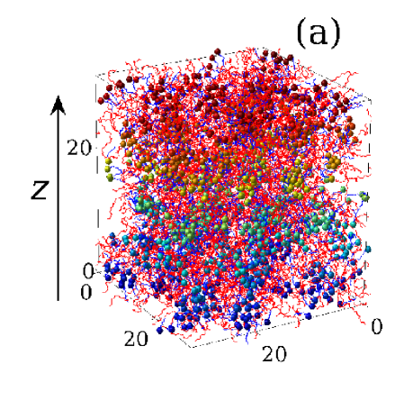
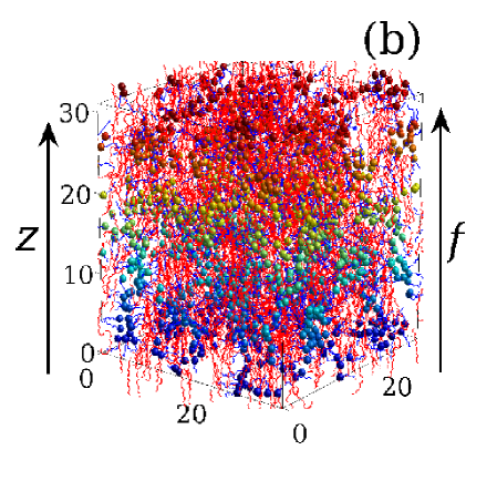
A snapshot of an equilibrated membrane with a water content of molecules per head group and in the absence of an applied stretching force is given in Fig. 1(a). The hydrophobic backbone and the side chains are shown as lines (red and blue respectively in the online version). The spheres indicate the sulfonate head groups of the sidechains, and show cluster-like aggregations of different sizes and shapes, in agreement with experimental observations mauritz2004 . A moderately stretched membrane with dimensionless stretching force =1 is shown in Fig. 1(b). The polymer backbone shows ordering in the direction of the applied force, which is parallel to the axis. We determine the induced backbone ordering and sidechain ordering by calculating the order parameter
| (7) |
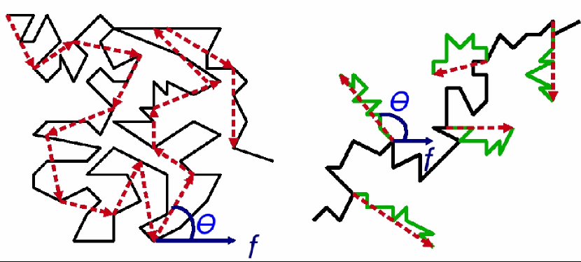
an approach commonly used in liquid crystal systems. Here for the backbone polymer and sidechains respectively, the angular brackets denoting statistical averaging over the ensemble. The orientational angle for each segment is defined as the angle between the vector connecting the first and last monomers of the segment and the applied force , as illustrated in Fig. 2. The backbone matrix is considered as a set of segments of 14 monomers each. If is larger than , the order of monomer numbering along the segment is reversed for a proper accounting its orientation. In a similar manner we define the orientational angle for sidechains as also shown in Fig. 2. Here is the angle between the stretching force and the vector pointing from the first monomer of the side chain towards its terminal group.
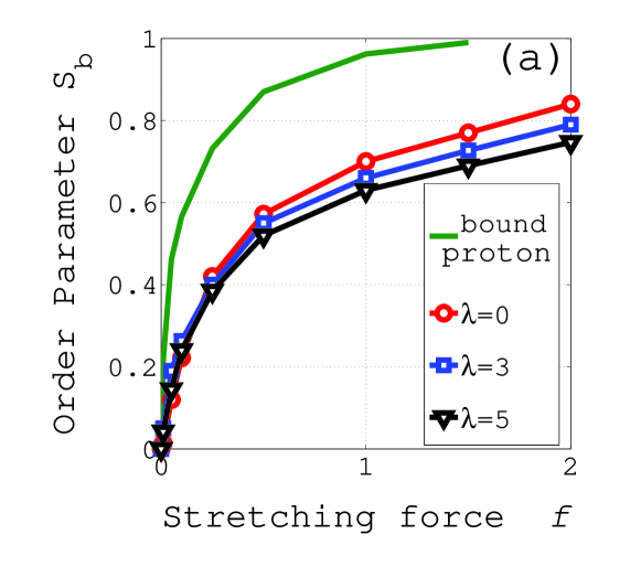
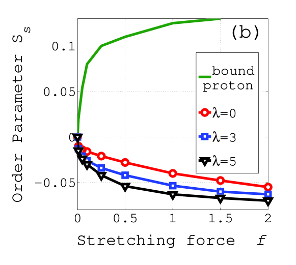
The order parameters and , calculated from Eq. (7), are shown in Fig. 3. As expected, membrane stretching leads to ordering in the ionomer conformation. The backbone ordering, shown in Fig. 3(a), is greatest in the bound-proton model and decreases in the solvated case as the water content increases for a fixed force . Figure 3(b) reveals the completely different response of the side chains to the stretching force. When the bound-proton membrane is stretched, the sidechains tend to orient themselves parallel to the stretching force. However when a solvated membrane is stretched, the sidechains are more likely to be perpendicular to the stretching force, in accord with previous experimental results chourdak . A possible explanation for these different responses to stress lies in the effect of the humidity on multiplet formation. In the absence of water, the dipolar interactions between sulfonates leads to the formation of dense multiplets containing 10–20 terminal groups, as seen in Fig. 4(a). The Coulomb forces of attraction between these dipoles limit the amount of molecular relaxation of the sidechains in response to stretching. The backbone deformation is thus followed by the rearrangement of multiplets via elongation in one direction and shrinking in the other direction. This is evident from a comparison of the curves for stretched and unstretched membranes in Fig. 4a.
In contrast, when the membrane is solvated, the water content lowers the densities of the multiplets. These then coalesce to form larger clusters in which a mixture of solvent molecules and conducting protons gives the head groups more dynamic flexibility. As a result, the sidechains can achieve a gain in entropy by rearranging themselves perpendicular to the direction of the applied stress. This is the reason why only a slight deformation of the multiplet geometry for the solvated membrane is seen in Fig. 4(b). In summary, the order parameter of the membrane depends on its hydration level, the absorbed solvent being an obstacle for the backbone ordering , but facilitating the side-chain ordering .
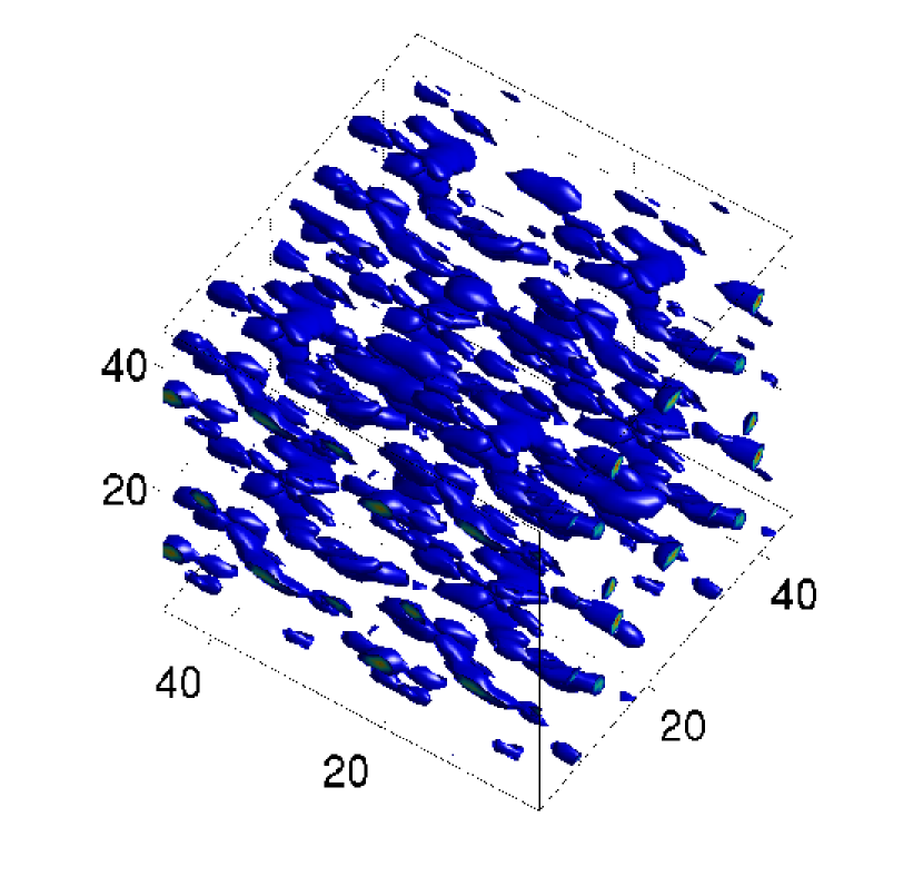
The most important aspect of the effect of stress on morphology concerns the formation of channels through which proton transport might occur. An indication of this is shown in Fig. 5, in which the water distribution in a stretched ionomer is displayed. The water molecules congregate in elongated clusters in association with the distribution of side-chain head-groups, and are oriented in the direction of the applied stress. During the course of the simulation, the clusters create temporary bridging connections allowing the water to diffuse easily back and forth along the stretching direction. This morphology and dynamics of the water undoubtedly facilitates proton diffusion parallel to the stretching direction.
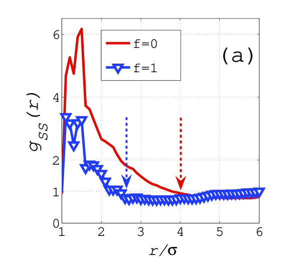
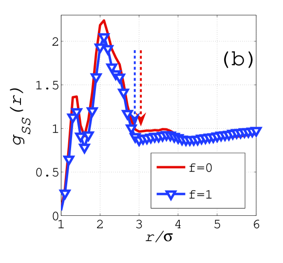
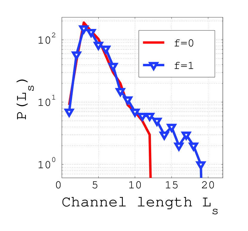
In order for proton conduction to occur, it is necessary for there to be a continuous network of pathways through the hydrophilic material in a membrane. This makes it useful to have a quantitative measure of the connectivity of the hydrophilic channels. To this end we have developed a method our-efield aimed at detecting hydrophilic pathways in a network of hydrophilic clusters. The only input parameter for this method is the maximum separation distance parameter between neighboring particles in the pathway. Our method calculates the distribution function of the hydrophilic channel length , which is defined as the distance between the initial and end points of the pathway. We applied this method to determine how the stretched-membrane morphology alters the channeling in the hydrophilic network of clusters. The distribution function when is chosen to be (which is 7Å, the average separation between sulfonates in Nafion) is shown in Fig. 6, both for stretched and unstretched membranes. Both curves have a similar short-range behavior and show a maximum at a most probable channel length equal to about 3. This is roughly the average size of the sulfonate multiplets in solvated membranes, as was seen in Fig. 4(b). The long-range behavior of , however, shows a dependence on the mechanical treatment of the membrane. In a stretched membrane the hydrophilic-sulfonic channels in the membrane are 50% longer than in an unstretched membrane. We note that the calculated is an instantaneous measure of the pathways in a network of clusters. Because of the constantly changing patterns in the distribution, which are caused by the diffusion of ions and water and the motion of head groups, the real pathways are effectively longer, and can even traverse the whole system. Consequently one expects that the protons in a stretched membrane can continuously travel along the stretching axis . We explore the resulting protonic conductivities in the next section.
V Results for the Conductivity of a Stretched Membrane
In this section we analyze the effect of membrane stretching on the protonic current. The electrical conductivity due to proton current in a solvated membrane can be obtained by performing NEMD simulations to find the current in the presence of an external electrostatic field through the relation
| (8) |
Here the induced current density is given by
| (9) |
where is the E-field component of the velocity of the ion, and is the total number of protons in the system.
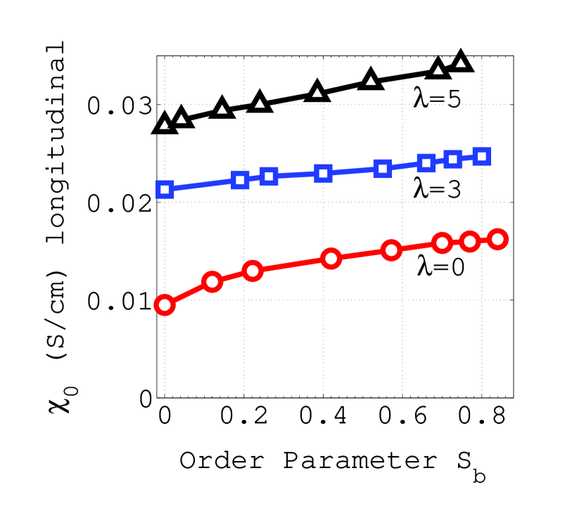
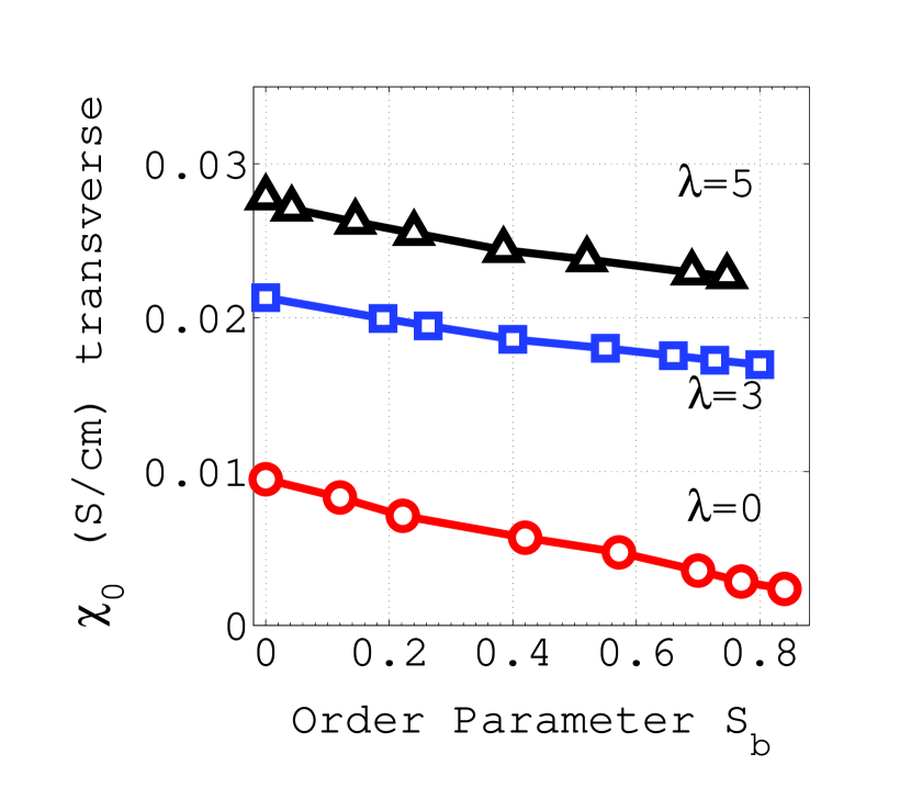
Because a strong applied electric field may itself have an effect on the morphology, we isolate the effects of stretching by examining only the limit of as . The longitudinal and transverse conductivities were evaluated by applying fields parallel and perpendicular to the stretching direction, and extrapolating the resultant conductivities to find their values at zero applied field. The calculated values of for the case where is along the membrane stretching axis are shown in Fig. 7 as a function of the membrane order parameter for different solvation parameters . It is seen that ordering in the membrane backbone increases the conductivity, with a dependence of on that is close to being linear for all water contents . Conversely, when we examine the transverse protonic conductivity across the stretched membrane, which is shown in Fig. 8, we find that the conductivity decreases with increasing backbone ordering. These two trends can be understood as a direct consequence of the channel-like nanophase separation along the stretching direction. While the protons can freely travel along these channels as a consequence of the water cluster bridgings, there are no continuous pathways for them to travel across the stretching direction. This anisotropy in the conductivity is most pronounced in the dryer samples.
VI Discussion and Conclusion
The simulation results presented in the previous sections show that the uniaxial stretching of a Nafion-like ionomer should be expected to have a significant effect on its proton conductivity. The conductivity along the stretching direction is considerably higher than its value in an unstretched membrane, while the proton diffusion perpendicular to the stretching axis is strongly reduced. When a water-containing sample is stretched, the perfluorinated side chains exhibit a tendency to be oriented perpendicular to the stretching force direction. The sulphonate clusters deform as the stretching is increased, and show a long-range ordering in their distribution across the membrane. This affects the distribution of absorbed water, which forms a continuous network with narrow bridges.
The effect of the water is different for the backbone and sidechain ordering parameters. As seen from Fig. 3, water is an obstacle to backbone ordering parallel to the direction of elongation. However, water enhances the sidechain ordering perpendicular to the stretching direction. For a given stretching force , the order parameter of the membrane backbone depends on the solvation parameter .
The simulations reported here were carried out at room temperature, and under conditions of constant stress, and we made no attempt to investigate how the anisotropy in the protonic conductivity depends on the temperature at which the membrane was stretched. Experimental measurements of crystallinity, however, indicate that membrane stretching at elevated temperatures can lead to different results from ambient-temperature stretching trevino ; cable1995 . It appears that uniaxial extension of membranes at temperatures above the boiling temperature of water results in a material with an oriented morphology that persists after the samples are removed from the extensional stress. Also, higher-temperature compression-molded ionomers exhibit a backbone crystallization when stretched bagrodia . It would thus be of interest to pursue further studies to enlarge on those presented here.
Finally, we note that with regard to the issue of improving fuel-cell performance by using stretched membranes, our results indicate that the observed increased proton conductivity occurs only in the direction of stretching. As a practical matter, the desired direction of proton transport is across the membrane, and so the production of a membrane with enhanced conductivity due to stress may be difficult to arrange.
Acknowledgements.
We acknowledge stimulating discussions with P. Pintauro and R. Wycisk, who introduced us to their membrane stretching experiments. E. A. thanks M. Litt for valuable comments on equilibrium ionomer morphologies. This work was supported by the US Department of Energy under grant DE-FG02-05ER46244, and was made possible by use of facilities at the Case ITS High Performance Computing Cluster and the Ohio Supercomputing Center.References
- (1) Eisenberg, A.; Hird, B.; Moore, R. B. Macromolecules 1990, 23 4098.
- (2) Gohy, J. F.; Jerome, R.; van den Bossche, G.; Sobry, R. Macromol. Chem. Phys. 1998, 199 2205.
- (3) Rubatat, L.; Rollet, A.; Gebel, G.; Diat, O. Macromolecules 2002, 35 4050.
- (4) Barbi, V.; Funari, S. S.; Gehrke, R.; Scharnagl, N.; Stribeck, N. Polymer 2003, 44 4853.
- (5) Gebel, G.; Diat, O. Fuel Cells 2005, 5 261.
- (6) Elliott, J. A.; Hanna, S.; Elliott, A. M. S.; Cooley, G. E. Macromolecules 2000, 33 4161.
- (7) Elliott, J. A.; Hanna, S. ; Elliott, A. M. S.; Cooley, G. E. Polymer Engineering and Science 2006, 46 228.
- (8) Cable, K. M.; Mauritz, K. A.; Moore, R. B. Chem. Mater. 1995, 7 1601.
- (9) Lin, J.; Wycisk, R.; Pintauro, P. N.; Kellner, M. Electrochemical and Solid-State Letters 2007,10 B19.
- (10) Elabd, Y.A.; Walker, C. W.; Beyer, F. L. Journal of Membrane Science 2004, 231 181.
- (11) Oren, Y.; Freger, V.; Linder, C. Journal of Membrane Science 2004, 239 17.
- (12) Cui, S.; Liu, J.; Selvan, M. E.; Keffer, D. J.; Edwards, B. J.; Steele, W. V. J. Phys. Chem. B 2007, 111 2208.
- (13) Blake, N. P.; Petersen, M. K.; Voth, G. A.; Metiu, H. J. Phys. Chem. B 2005, 109 24244.
- (14) Jang, S. S.; Molinero, V.; Cagin, T.; Goddard III, W. A. J. Phys. Chem. B 2004, 108 3149.
- (15) Wescott, J. T.; Qi, Y.; Subramanian, L.; Capehart, T. W. J. Chem. Phys. 2006, 124 134702.
- (16) Vishnyakov, A.; Neimark, A. V. J. Phys. Chem. B 2001, 105 7830; 2001, 105 9586.
- (17) Yamamoto, S.; Jinnouchi, R.; Yamakawa, Sh.; Hyodo, Sh. 14th International Conference on the Properties of Water and Steam, Kyoto, Japan 2004, 411.
- (18) Allahyarov, E.; Taylor, P. L. J. Chem. Phys. 2007, 127 154901.
- (19) Paddison, S. J.; Zawodzinski, T. A. Solid State Ionics 1998, 113-115 333.
- (20) Iversen, G.; Kharkats, Yu. I.; Ulstrup, J. Molecular Physics 1998, 94 297.
- (21) Kreuer, K. D.; Paddison, S. J.; Spohr, E.; Sschuster, M. Chem. Rev. 2004, 104 4637.
- (22) Paul, R.; Paddison, S. Mat. Res. Soc. Symp. Proc. 2001, 677 AA7.16.1.
- (23) Taylor, P. L.; Xu, B. C.; Oliveira, F. A.; Doerr, T. P. Macromolecules 1992, 25, 1694.
- (24) Lin, H.-L.; Yu, T. L.; Huang, C.-H.; Lin, T.-L. J. Polymer Science B: Polymer Physics 2005, 43 3044.
- (25) Chan, K.; Tang, Y. W.; Szalai, I. Molecular Simulations2004, 30 81.
- (26) Vishnyakov, A.; Neimark, A. V.; J. Phys. Chem. B 2000, 104 4471; Rivin, D.; Meermeier, G.; Schneider, N. S.; Vishnyakov, A.; Neimark, A. V. J. Phys. Chem. B 2004, 108 8900.
- (27) Glotzer, S. C.; Paul, W. Annu. Rev. Mater. Res. 2002, 32 401.
- (28) Mazars, M. J. Chem. Phys. 2001, 115 2955.
- (29) Mauritz, K. A.; Moore, R. B. Chem. Rev. 2004, 104 4535.
- (30) Chourdakis, N.; Voyiatzis, G. A. J Polym. Sci. Part B: Polym. Phys. 2007, 45 2509.
- (31) Allahyarov, E.; Taylor, P. L. submitted to Phys. Review E 2008.
- (32) Trevino, S. F.; Young, S. K. Army Research Labarotory Report 2002.
- (33) Bagrodia, S.; Mohajer, Y.; Wilkes, G. L. Polymer Bulletin 1982, 8 281.
- (34) Bauer, F.; Denneler, S.; Willert-Porada, M. J. Pol. Sci. Part B: Pol. Phys. 2005, 43 786.