Superantenna made of transformation media
Abstract
We show how transformation media can make a superantenna that is either completely invisible or focuses incoming light into a needle-sharp beam. Our idea is based on representating three-dimensional space as a foliage of sheets and performing two-dimensional conformal maps on each sheet.
PACS 42.15.-i, 42.15.Eq, 42.15.Dp
1 Introduction
Transformation optics [1, 2, 3, 4, 5, 6, 7] has the potential to transform optics, both by developing new ideas for the design of optical instruments and by stimulating research into new optical materials. Transformation optics uses the fact [6] that optical media alter the geometry of space and time for light.111For a review see Ref. [7]. A transformation medium performs an active coordinate transformation: electromagnetism in physical space, including the effect of the medium, is equivalent to electromagnetism in transformed coordinates where space appears to be empty. The sole function of the device is to facilitate a transformation from physical to electromagnetic space. One of the most striking applications of transformation optics is invisibility [1, 2, 3, 5]; a cloaking device creates a coordinate transformation that carries a hole for hiding objects. But invisibility is by no means the only application: perfect lensing based on negative refraction also implicitly uses coordinate transformations [6] — multivalued transformations — although the original argument [8] why negative refraction makes a perfect lens did not make use of this fact. Similarly, the performance of cloaking devices can be theoretically verified by other means than coordinate transformations [9], but the ideas of transformation optics provide an elegant, visual way of designing optical devices. Such visual thinking often leads to new insights and inventions.
Here we discuss an idea for a superantenna based on coordinate transformations. This device is either invisible or it condenses a cross section of light into a single point. Ideally, the condensed light would continue to propagate as a needle-sharp beam in a given direction, but there might be practical limitations to this behavior. Our idea certainly is not the only case where optical condensors based on transformation media have been described [3, 4, 10], but it may have unique three-dimensional properties, because it changes the topology of space. Most nontrivial applications of transformation media use topology transformations: spaces with holes in the case of invisibility [6], multivalued spaces for perfect lensing [6], topological bridges for electromagnetic wormholes [11] and space-time horizons [6] for artificial black holes. Our idea relies on a three-dimensional extension of optical conformal mapping [3, 4] as we describe below.
2 Transformation
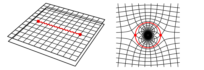
Imagine we represent three-dimensional space as a foliage of spherical layers (such that it resembles an onion), as illustrated in Fig. 1. Each layer we map onto an individual plane by stereographic projection [4, 12, 13], each layer is a Riemann sphere [12, 13], see Fig. 2. Expressed in terms of analytical geometry, the Cartesian coordinates , , of physical space are represented by spherical radii and dimensionless complex numbers that correspond to the stereographic projections of the spherical angles. In formulae,
| (1) |
Then we perform a conformal transformation on , mapping to where the mapping may vary with the radius , but should only depend on and not on ,
| (2) |
The main advantage of such restricted maps is that they allow us to use the plethora of tools and insights of complex analysis, because the condition corresponds to the Cauchy-Riemann differential equations of analytic functions [13]. The map generates a Riemann surface that consists of several Riemann sheets, unless is a Möbius transformation [12]. Finally we map the sheets back on the Riemann sphere of electromagnetic space by the inverse stereographic projection [12, 13]
| (3) |
On each individual Riemann sphere, the transformation (2) is conformal [12, 13, 14] — it preserves the angles between lines — but the transformation is normally not conformal in three-dimensional space, where the Cartesian coordinates , , are mapped onto new coordinates , , and vice versa. In the spirit of transformation optics [6], the new coordinates are the coordinates of a virtual space, electromagnetic space, that we assume to be completely empty, where light propagates along straight lines. The device transforms the straight light rays of electromagnetic space into appropriately curved rays in physical space. Moreover, it not only transforms rays, but complete electromagnetic waves.
An example of a sufficiently simple but interesting conformal transformation is the Joukowski map (Zhukovsky map) known from aeronautical engineering [15]
| (4) |
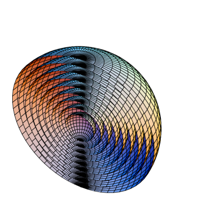
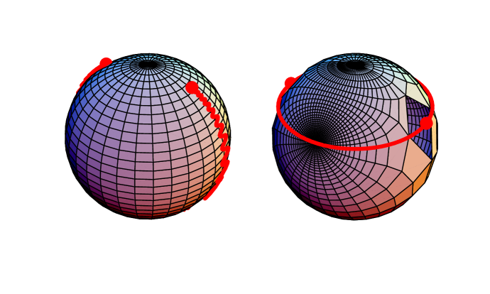
Equation (4) describes a conformal map between the plane and two Riemann sheets in space. Or, in terms of Riemann spheres, for each radius , two spheres in electromagnetic space are merged into one sphere in physical space, as illustrated in Fig. 3. The image of each one of the two Riemann spheres occupies a certain spherical angle in physical space.
This topology makes a perfect trap: in electromagnetic space light may pass from one of the two spheres to the other, and it will stay there. In physical space, however, the spherical angle of the second Riemann sphere may shrink to a point where light is concentrated. The entrance to the trap is marked by the branch points in space, i.e. by the points . These points are variable, because is a function of the radius . Therefore, one could catch incoming light by rapidly making very large when the light gets sufficiently close, say for smaller than a critical radius . When the light has passed from the first Riemann sphere to the second one it will continue to propagate on the second sphere. As the radius grows again, the fraction of real space occupied by this sphere is diminishing to zero, the trap closes: light is concentrated and funneled into a needle-sharp beam.
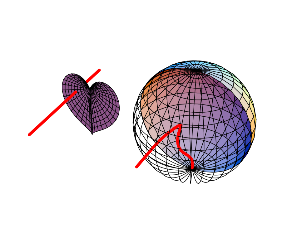
What is the cross section of the captured light? The cross section in physical space is identical to the cross section in electromagnetic space, because, outside of the device, physical and electromagnetic space are identical. In electromagnetic space light rays travel along straight lines. Here the portal to the trap is marked by the line of the branch points . Consequently, the cross section in real space is bounded by the curve of the branch points in electromagnetic space, by the inverse stereographic projection of . Figure 4 shows an example that is given by the radius-dependent branch points
| (5) |
where describes the maximal extension of the branch cut at . The captured light has entered the second Riemann sphere in electromagnetic space that shrinks into the point on the Riemann sphere in physical space when approaches . So, in physical space, the captured light rays are concentrated in the spatial direction given by the image of in the inverse stereographic projection, i.e. along the negative axis. Figure 4 shows how the device funnels a captured light ray towards this axis; Fig. 5 illustrates the fate of a circle of light rays. The device acts like a superantenna, focusing incident electromagnetic radiation into an area that is, in principle, infinitely small. Moreover, and quite remarkably, the focus is independent of the direction of incidence, in contrast to the focusing by normal lenses or mirrors. The theory would suggest that the captured electromagnetic radiation is concentrated in an infinitely narrow beam. In practice, of course, both the focus and the beam will be limited, but assessing these limitations goes beyond the scope of this paper, beyond the area of transformation optics.
3 Media
What are the requirements to implement such a superantenna in practice? Perhaps the most elegant way of calculating the material properties of this device is using the connection between transformation media and general relativity [6, 7]. For this, we need to establish the geometries that correspond to the stereographic coordinates (1) and their transformation (2). We denote the metric tensor of the stereographic coordinates by and the metric tensor of the transformed coordinates by (using the notation of Ref. [7]). The line element in physical space is given by
| (6) |
The geometry of the transformed coordinates is characterized by the equivalent line element (6) in electromagnetic space, but expressed in real-space coordinates,
| (7) |
For formulating a compact notation for the metric in electromagnetic space we define such that, for example, . From the line element (7) we read off the matrix of the metric
| (8) |
We obtain the metric tensor of the stereographic coordinates of real space by putting in or by directly reading off the tensor from the line element (6). The square root of the determinant of the metric tensor describes the volume element. We put the matrix (8) in explicit form and calculate the determinant:
| (9) |
The inverse matrix describes the contravariant metric tensor and is given by
| (10) |
with defined as the vector of and understood as a function of and . One can verify that Eq. (10) indeed describes the inverse matrix of using the relations
| (11) |
According to the connection between optical media and geometry [6, 7] the contravariant electric permittivity tensor in stereographic coordinates is
| (12) |
The magnetic permeability tensor should be identical to (impedance matching). The matrix (12) describes a contravariant tensor; the eigenvalues of are not invariant under coordinate transformations, but the eigenvalues of the mixed tensor are [7]. Therefore they correspond to the eigenvalues of the electric permittivity in Cartesian coordinates that characterize the dielectric response of the anisotropic material used to implement the coordinate transformation (2). We calculate the three eigenvalues of and obtain
| (13) |
with the abbreviations
| (14) |
One of the eigenvalues, , is always unity, which reflects the fact that the coordinate transformations (2) act on two-dimensional manifolds, although they cover layer-by-layer the entire three-dimensional physical space as shown in Fig. 1. Close to the focal line of the device at (in negative direction) we would expect that the eigenvalues of the dielectric tensor become singular. We find for the transformation (4)
| (15) |
Since vanishes at one of the eigenvalues indeed is singular. In practice, the dielectric functions will always be finite, which limits the achievable focus of the antenna and may also influence the width of the beam funneled into the negative direction. In order to estimate these effects and to develop the optimal strategy for regularizing the singularity at the focus, one could perhaps use similar mathematical techniques as the ones applied for assessing the regularization of invisibility devices [16].
4 Outlook
Our principal ideas are by no means restricted to superantennae, but they could serve to design other novel optical devices as well. One could imagine other foliages of three-dimensional space than the Riemann spheres of Fig. 1 and consider conformal maps on them. The important point is that such three-dimensional foliages allow researchers to make use of the tools of two-dimensional conformal mapping. In this way, a rich arsenal of insights, techniques and tools becomes available for designing optical instruments, the theory of complex analysis and conformal mapping [12, 13, 14] that has reached a high level of development and sophistication, and combines, like no other branch of mathematics, analytical techniques with visual thinking.
We are grateful to T. G. Philbin for helpful comments. The paper has been supported by COVAQIAL and a Royal Society Wolfson Research Merit Award.
References
- [1] A. Greenleaf, M. Lassas, and G. Uhlmann, Physiol. Meas. 24, S1 (2003).
- [2] A. Greenleaf, M. Lassas, and G. Uhlmann, Math. Res. Lett. 10, 1 (2003).
- [3] U. Leonhardt, Science 312, 1777 (2006).
- [4] U. Leonhardt, New. J. Phys. 8, 118 (2006).
- [5] J. B. Pendry, D. Schurig, and D. R. Smith, Science 312, 1780 (2006).
- [6] U. Leonhardt and T. G. Philbin, New J. Phys. 8, 247 (2006).
- [7] U. Leonhardt and T. G. Philbin, arxiv:0805.4778, to appear in Prog. Optics.
- [8] J. B. Pendry, Phys. Rev. Lett. 85, 3966 (2000).
- [9] Z. Ruan, M. Yan, C. M. Neff, and M. Qui, Phys. Rev. Lett. 99, 113903 (2007).
- [10] A. V. Kildishev and V. M. Shalaev, Opt. Lett. 33, 43 (2008).
- [11] A. Greenleaf, Y. Kurylev, M. Lassas, and G. Uhlmann, Phys. Rev. Lett. 99, 183901 (2007).
- [12] T. Needham, Visual Complex Analysis (Clarendon Press, Oxford, 2002).
- [13] M. J. Ablowitz and A. S. Fokas, Complex Variables (Cambridge University Press, Cambridge, 1997).
- [14] Z. Nehari, Conformal Mapping (McGraw-Hill, New York, 1952).
- [15] J. Anderson, Fundamentals of Aerodynamics (McGraw-Hill, Toronto, 1991).
- [16] A. Greenleaf, Y. Kurylev, M. Lassas, and G. Uhlmann, Commun. Math. Phys. 275, 749 (2007).