Joint Cooperation and Multi-Hopping Increase the Capacity of Wireless Networks
Abstract
The problem of communication among nodes in an extended network is considered, where radio power decay and interference are limiting factors. It has been shown previously that, with simple multi-hopping, the achievable total communication rate in such a network is at most . In this work, we study the benefit of node cooperation in conjunction with multi-hopping on the network capacity. We propose a multi-phase communication scheme, combining distributed MIMO transmission with multi-hop forwarding among clusters of nodes. We derive the network throughput of this communication scheme and determine the optimal cluster size. This provides a constructive lower bound on the network capacity. We first show that in regular networks a rate of can be achieved with transmission power scaling of , where is the signal path-loss exponent. We further extend this result to random networks, where we show a rate of can be achieved with transmission power scaling of in a random network with unit node density. In particular, as approaches 2, only constant transmission power is required. Finally, we study a random network with density and show that a rate of is achieved and the required power scales as .
I Introduction
Understanding the feasibility of multi-hop wireless networks has been the subject of a great deal of research. In this regard, much mathematical and practical consideration has been devoted to studying the capacity of such networks. In the seminal work of Gupta and Kumar [1], it has been shown that under the assumption of point-to-point communication, the per-node asymptotic capacity decays at least as fast for a dense network with nodes, where the number of nodes approaches infinity within a unit disk or unit sphere. Subsequent studies have shown similar decay for upper-bound on capacity in an extended network, where the deployment area increases linearly with the number of nodes while the node density remains constant [2][3][4]. In such networks, besides interference, the radio power decay over large communication distances is another determining factor affecting the communication rate.
The results of [1] are based on the assumption that the communication between a specific source-destination pair is always deteriorated by the concurrent transmission of the other nodes. In contrast, cooperative communication can result in considerable capacity gains by discarding this constraint. Under this setting, the notion of a link is considered as a set of users, encoding and transmitting messages in coordination. Such a communication setting mimics a Multiple-Input Multiple-Output (MIMO) antenna system [5] in a distributed fashion, where users act as virtual antenna arrays cooperating to transmit a message towards the destination.
Exploiting the spatial multiplexing gain of MIMO is appealing, since MIMO communication can result in linear capacity increase as a function of the number of antennas in the high SNR regime [5]. Furthermore, Ozgur et al has recently extended this result to distributed MIMO communication [6] to achieve linear capacity scaling with in a dense network with constant transmission power, by utilizing a hierarchical communication scheme with single-hop distributed MIMO transmission between the source and destination clusters. However, multi-hop forwarding is essential to the efficiency of large-scale extended networks. It remains an open problem to quantify the capacity of multi-hop cooperative communication.
This work represents a step toward this direction. We extend our results in [7] and study the benefit of cooperation in an extended network, by combining peer-node cooperation with multi-hop forwarding to mitigate the path-loss power decay and harness spatial multiplexing gain. We propose a multi-phase communication scheme based on multi-hop distributed MIMO forwarding among clusters of nodes, where a cluster is a hierarchically organized set of nodes that cooperate simultaneously to transmit a single message vector. We then derive the network throughput of this communication scheme by considering the optimal cluster size. We first show that, for a regular network, where one node is randomly placed within each square of unit area, the network throughput scales as with transmission power requirement of , where is the signal path loss exponent. We further extend this result to a random network, where the nodes are uniformly distributed with unit node density, and show that throughput scaling is lower-bounded by with transmission power requirement of . We finally study a random network with increasing node density and show that if the density follows the throughput scaling is lower-bounded by with power scaling . The existence of the proposed communication scheme provides a constructive lower bound on the capacity of extended networks with node cooperation.
The rest of the paper is organized as follows. In Section II, we summarize the related work. Section III details the network model. In Section IV we explain the three phases of the communication scheme. Section V analytically evaluates each communication phase and presents the overall network capacity. We extend our results to random networks in Section VI. Finally, the concluding remarks are given in Section VII.
II Related Work
Existing research on the scaling behavior of multi-hop wireless networks can be categorized mainly into two groups. The first category is concentrated on information-theoretic upper-bounds on the network capacity by using cut-set bounds, and the second category deals with constructive communication schemes which achieve a lower-bound on the capacity. Different topologies such as dense and extended networks have been considered in each category.
Information Theoretic Upper-bounds: The seminal work [1] provides both upper-bounds and constructive communication schemes to show that the point-to-point capacity of a dense wireless network is . In [2], [3], [4], and [8], the authors derive information theoretic upper-bounds on the network capacity. These works study the capacity scaling of extended networks and obtain upper-bounds on the capacity by using cut-set bounds. In particular, Xie et al prove that for environments with path-loss exponent and constant per node power, the expected transport capacity grows at most linearly in the number of nodes, so that for an extended network with uniformly distributed source-destination pairs, the network capacity is [4].
While in simple multi-hopping, increasing the transmission power does not improve the capacity scaling, Jovicic et al in [2] show that the upper-bound on the network transport capacity scales linearly with node power. Similar results are shown in [4]. Their results motivates using the extra degree of freedom provided by the choice of transmission power. We exploit this in the proposed collaborative scheme to increase the network capacity.
Constructive Communication Schemes: Toumpis et al in [9] have proposed a gridding of a unit area network and the use of 9-TDMA scheduling to derive the same lower-bound on capacity as [1] in a more straightforward manner. They further extend their model to consider the effect of node mobility and fading on the capacity. Franceschetti et al in [10] have closed the previous gap between the capacity in arbitrary and random networks. They use percolation theory to show that the sum capacity of their proposed communication scheme scales as . None of the above utilizes cooperative transmission.
There has been much research into node cooperation in the context of single-source, single-destination, and relays. For example, Gastpar et al in [11] show an achievable rate scaling of . However, Ozgur et al in [6] are the first to exploit the linear-scaling result of MIMO communication in a multiple-source network using a distributed MIMO paradigm. For a dense network, they propose a hierarchical cooperative communication scheme with single-hop distributed MIMO transmission to achieve a network throughput scaling of , , and single-hop distributed MIMO transmission. They further show that when the same scheme is applied to the more realistic extended network model, it results in a throughput , implying that for , the scheme outperforms simple multi-hopping.
Our work is motivated by [6]. However, we propose a multi-hop distributed MIMO scheme specifically designed for extended networks. Furthermore, we show that with a small increase in the transmission power, our scheme performs uniformly better than simple multi-hopping for all values of . As far as we are aware, there is no existing work on analyzing the achievable rate of combining cooperative communication and multi-hop forwarding.
Finally, Aeron and Saligrama in [12] have studied the effect of node cooperation on the capacity of wireless networks with a fixed receiver SNR at all nodes and obtained network throughput, through spatially separated MIMO relays which collaborate in their transmissions. However, the assumption of constant receiver SNR at all nodes implies that the transmission power needs to scale as . In contrast, in this work we show that with much lower power scaling, the same communication rate can be achieved by using multi-hop distributed MIMO transmissions.
III Network Model
We consider an extended network with nodes distributed within the area . We first evaluate the capacity results for nodes following a special topology that we call a regular network. In a regular network, we divide to squares of unit area and assume there is exactly one node in each such square. We then generalize our results to a random network, where nodes are distributed independently and uniformly over the area .
A matching of the source-destination pairs is picked at random, so that each node is the destination of exactly one source. It is assumed that the sources are all sending their messages with a common source-to-destination rate bits/sec, and the total network throughput is bits/sec. Each node divides its messages into sub-blocks of length bits and sends packets with length equal to a multiple of during the communication with its intended receiver. It will be clear later that the proper sub-block size depends only on the MIMO transmission details and does not affect the throughput scaling analysis. In contrast, the multiplier to is an optimization parameter dependent on the optimal size of a cluster which will be explained in detail in Section V.
Similar to the model of [1][6][10][12], we consider a line-of-sight environment without fading or shadowing. The channel gain between two nodes and in the network is assumed to follow a standard baseband model and can be written as
| (1) |
where is the Euclidean distance between the two nodes, is the unit imaginary number, is the phase change distributed uniformly and independently in [5], and is the path loss exponent, such that the power of the received signal at node from node equals , where is the transmission power of node . Then, the received message at node at time can be expressed as
| (2) |
where represents the set of active senders at time transmitting signals to node , which can be added constructively [5], is the received message at node at time , is the additive white Gaussian noise at node with variance , and is the interference from the nodes which are destructive to the reception of node . We do not consider sophisticated multi-user detection techniques at the receiver nodes and simply treat interference as noise to obtain a lower-bound on the network capacity. Furthermore, since we are proposing a constructive lower-bound on the capacity, during each communication phase, a network topology which results in the lowest communication rate is considered. Therefore, the dependency of the channel gains on time can be removed in our analysis.
IV Communication Scheme
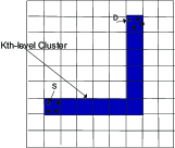
We consider a communication scheme whose rate provides a constructive lower-bound on the network capacity. We arrange the nodes into a hierarchical level clustering structure, each level consisting of 9 non-overlapping lower-level clusters in a 3-by-3 formation, such that the th-level cluster refers to the set of nodes that lie in a square of area , as depicted in Fig. 1(a). Unless otherwise stated, we use the term cluster synonymously with the term th-level cluster.
The proposed scheme is comprised of three phases, intra-cluster message dissemination from the source to all nodes in its cluster, inter-cluster message forwarding toward the destination node’s cluster, and message decoding at the destination. In the following we explain the transmission scheme in each phase for the regular network. The generalization to the case of a random network follows the same structure and the difference is explained in Section VI. Throughout the paper, we use the notation , for the transmission power during the th phase.
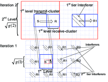
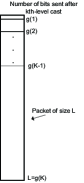
Phase 1: Intra-Cluster Communication. The goal of this phase is to distribute each source node’s message to the set of nodes in the source’s cluster (which will serve as relays for the source in the next phase). We utilize a hierarchical cooperation strategy carried out in iterations as shown in Fig. 1(a). Each source node divides its message to packets of length bits, (i.e., g(K) sub-blocks and bits per sub-block). The packet’s transmission is carried out in a -level progression as shown in Fig. 1(b), such that after the th iteration, the source will have forwarded bits of its packet. We assume that the nodes transmit with a common constant power during this phase. The details of this iterative communication scheme are given in the following.
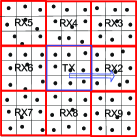
Two th-level clusters are said to be neighbors if their boundaries touch. Therefore, each th-level cluster has 8 neighbors. To avoid interference from neighboring clusters, TDMA is used to schedule transmission among the 9 partitioning th-level clusters within a th-level cluster. This is called a 9-TDMA scheme. As shown in Fig. 2(a), 9-TDMA implies that, during the th iteration, only one among the nine th level clusters acts as the transmit-cluster, and its eight neighbor clusters are potential receive-clusters. The th level transmit- and receive-clusters communicate using distributed MIMO transmission. We call each such communication a th-level cast. At the receive-cluster side, during the th-level cast, each of the th-level receive-clusters is set to active receive mode in a round-robbin manner, based on a specific order as depicted in Fig. 2(a).
During the first iteration, an active source performs 8 consecutive st-level casts to transmit a different sub-block of bits to each of its 8 neighbor nodes and keeps bits in its own buffer. Hence, at the end of the first iteration, the 1st-level cluster contains bits. During the second iteration, as depicted in the 2nd-level in Fig. 1(a), the nodes inside the first level transmit-clusters act as distributed antennas, sending their messages at the same time. Thus, during each nd-level cast, bits are sent simultaneously using distributed MIMO to one of the 8 neighbor receive-clusters of size . Note that concurrently with this, the source can distribute another set of bits to its 1st-level cluster in preparation for the next 2nd-level cast.111This operation assumes the full-duplex communication, which is common in multi-hop capacity analysis [1]. If only half-duplex communication is available, the 1st-level source-cluster will simply wait for the source to send sufficient data before each 2nd-level cast. The same procedure can be applied in all levels, and it is easy to show that the resultant increase in transmission time does not change the scaling of the optimal cluster size or the network throughput. Hence, through 8 consecutive 2nd-level casts, bits of the source are transmitted in this iteration to the 2nd-level cluster. This pattern repeats, so that in the th iteration, bits of the source are transmitted to the th-level cluster. The number of iterations, , and therefore the required time, , to finish this step are design parameters to be found in Section V.
Later, to determine the effect of interference on the network throughput, we note that the set of interferer clusters imposed by 9-TDMA follows the pattern depicted in Fig. 1(a), where R represents the th-level receive-cluster. The shaded transmit-clusters, with corresponding receive-clusters labeled ‘R1’, act as interferers (1st tier interferers), since they are transmitting synchronously during R’s reception. It is clear that in the th tier there are interferers. (Some of the 2nd tier interferers are depicted in the figure). As the clusters increase in size, we still have the same pattern for the interferers’ locations. This can be better seen in Fig. 1(a) by considering the 2nd-level cast, where the spatial separation of interferers is multiplied by 3 from that of the 1st-level cast.
Phase 2: Inter-Cluster Communication. The goal of this phase is to deliver the message vector of length bits from the source-clusters towards the destination-clusters in a multi-hop fashion. By a destination-cluster, we mean a cluster of size that includes the corresponding final destination for a specific source node. We consider a cluster-based routing scheme in which hop-by-hop communication between neighboring clusters is performed either horizontally or vertically as shown in Fig. 3. Each intermediate cluster along the path is called a relay-cluster, which acts as a distributed multi-antenna system to forward its received message vector.
In the first hop, the nodes of the transmitting relay-cluster independently encode the message vector to symbols using a Gaussian code-book of power . In Section V-B, we will show that within each hop symbols are transmitted in one shot and we benefit from spatial degrees of freedom in MIMO communication. These symbols are sent synchronously to the receiving relay-cluster. The nodes in the receiving relay-cluster then amplify their receive observation to meet the power requirement , and forward it to the next cluster along the horizontal path. Such message propagation continues until the message vector reaches the cluster with the same vertical boundaries as the destination cluster, as illustrated in Fig. 3. Then, the hop-by-hop distributed MIMO communication among the clusters is performed vertically until the message vector reaches the destination cluster. We denote the required time to complete the routing of a node’s message by .
Phase 3: Message Decoding at the Destination. In this phase, each node in the destination cluster has an observation of the message transmitted by the source . The nodes each quantize their observation into bits and synchronously transmit the quantized observations towards the destination using a common constant power . This communication setting can be considered as a simple distributed Multiple-Input Single-Output (MISO) system in the destination cluster. We again use a 9-TDMA scheduling in this phase to determine the active clusters for transmission, which results in interference mitigation. We denote the required time to complete message transmission from the destination cluster to the destination node by .
V Scaling Laws for Regular Networks
In this section, we derive the asymptotic achievable network throughput using the proposed communication scheme. It is clear that the efficiency of this scheme hinges on the optimization of the cluster (th-level cluster) size. While larger clusters result in higher MIMO gain, better interferer separation, and lower cluster-hop count, the nodes inside large clusters need to distribute their messages to a large number of nodes and compete with many nodes for medium access. By considering such tradeoffs, we derive the optimal cluster size to minimize the total transmission time of the three communication phases. Note that the communication overheads, such as node scheduling and hierarchy formation, are negligible in the long run and are ignored in our analysis [6][9][10].
V-A Intra-Cluster Communication
During the th iteration of intra-cluster message dissemination, a th-level cluster transmits a message vector to each of its 8 neighboring th-level clusters in 8 consecutive th-level casts. We now derive a lower-bound on the achievable rate, denoted , during each such transmission.
Consider two adjacent squares of side length which share an edge. The achievable communication rate between the corresponding two th-level clusters can be expressed using MIMO capacity results [13]. Using a notation similar to the one we adopted in (2), the vector of the received messages at the th-level receive-cluster can be expressed as
| (3) |
where represents the channel matrix. Treating the interference simply as another source of noise, the interference plus noise power at a node in the receive-cluster is given as , where represents the interference power at during the th-level cast. In order to derive a capacity lower-bound, we can replace the interference power at all of the nodes inside a specific th-level cluster by . Assuming that the transmitted signals, , are iid and chosen from an Gaussian distribution and perfect channel state information is available at the receive cluster, the mutual information between the transmit- and receive-clusters is lower-bounded by the special case of Gaussian noise plus interference. Hence, we have
| (4) |
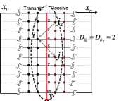
We now derive a more useful expression to replace the above general form. An example of intra-cluster MIMO communication is depicted in Fig. 2(a) for 1st-level clusters of size . The worst case topology happens when the transmitters are located at the furthest possible distance from the receivers. Figure 2(b) demonstrates such a topology in the 3rd-level cast for two horizontally adjacent 2nd-level clusters of size . Without loss of generality, we label the border (e.g., center red line in Figure 2(b)) between the two adjacent th-level clusters as the reference -coordinate. Then, given the constraint that there is one node inside each square, setting the transmit nodes’ -coordinates to , and the receive nodes’ -coordinates to results in maximum separation between them.
We next find the -coordinates for the worst case topology. We focus on the transmit and receive nodes which lie in squares adjacent to the border. The -coordinate for other nodes follows the same structure by symmetry. We index the -coordinates of the horizontal edges from 1 to as shown in Fig. 2(b). In general it is not easy to find the indices along the transmit and receive edges that minimize . However, for our analysis, since there is a horizontal distance of at least two between any two nodes chosen from the transmit and the receive clusters (i.e., ), we have . For , the small value of facilitates tight lower-bounds for the MIMO communication rate between the two adjacent clusters. Lemma 1 below states that the construction of this lower-bound is equivalent to finding the -coordinate for transmit and receive nodes such that is minimized, where represents the set of nodes in the th-level transmit-cluster and is the set of th-level receive-cluster nodes. Lemma 2 then provides the explicit -coordinates. The proofs are given in the appendix.
Lemma 1
The capacity expression is tightly lower-bounded by , where Tr is the matrix trace operation.
Lemma 2
The lowest rate in a th-level cast is achieved when the nodes on the transmit side are located at and the nodes on the receive side are located at or vice versa due to symmetry.
We next use Lemmas 1 and 2 to derive the achievable communication rate. We define the vertical distance between two nodes and as . Clearly, . In order to evaluate we have to quantify the number of transmit-receive pairs , along and , which are located at a specific vertical distance from each other. We denote this quantity by .
For a given vertical separation, , between a pair of nodes, we have
The above sum can be written as , where
| (5) |
In order to evaluate , we first quantify the number of nodes , with distance from a node located at , , in the th-level transmit-cluster. It is clear that .
The following facts are used to compute :
-
Each node in the transmit-cluster (except ) has 1 node of vertical distance 0 from it at the receive-cluster.
-
If but , or but , there is one node located at distance from node .
-
If and , there are two nodes at distance from node .
-
For all and , if , then it cannot be used in computing , since by Lemma 2 is removed from the set of receiver indices.
Hence, we can quantify as follows:
where represents the indicator function, such that it equals to 1 if its condition holds and 0 otherwise.
Summarizing the above, we have
| (6) |
Given , Lemma 3 below states the scaling law of . The proof is given in the appendix.
Lemma 3
As ,
Using the above lemmas, we characterize the intra-cluster communication time. During the th iteration, we denote by the minimum spatial separation between the interferers which are located at tier and a node inside the receiving cluster. Because of the 9-TDMA transmission scheme, there are at most tiers during the th iteration. In order to obtain an upper-bound on the interference, we assume that all of the nodes in an interferer cluster are located at the closest boundary to the receive-cluster R. Therefore, . Hence, the interference is upper-bounded as
| (7) |
where is a constant.
Eqn. (7) suggests the following. By increasing the size of the clusters, due to the scheduling algorithm, the spatial separation of the interferer nodes from the receive-cluster increases. Although the number of nodes inside each cluster is increasing, the overall effect of interference diminishes. Hence, in the limit, for large clusters, the communication becomes noise limited. Therefore, we have the following conclusion.
Proposition 1
As , during a th-level cast,
Proof:
Since the proposed intra-cluster communication uses iterative steps to distribute all bits of the source to the nodes inside the th-level cluster, the time required to finish this phase is
| (8) |
where represents the time taken to finish the th iteration. In the th iteration, 9 consecutive th-level casts are performed, each with a rate of . At the same time that MIMO transmission is in effect between two neighbor th-level clusters of size , the th-level transmit-cluster receives new packets to transmit them to another adjacent cluster of size during the next MIMO transmission. The required time to finish the th iteration is, therefore, equal to the maximum of these two times. Since bits are sent in one shot during each such transmission using MIMO communication, we have
| (9) |
for a constant and . This can be easily shown by induction since is a constant. This leads to the following conclusion.
Proposition 2
The total required time to finish the intra-cluster communication phase is .
Proof:
Since , the time required to finish the broadcasting of each node’s packet is upper bounded as
| (10) |
Hence, . Since this step has to be repeated times for all of the nodes inside each th-level cluster, the total required time is . ∎
V-B Inter-Cluster Communication
We derive a lower bound for the achievable rate, denoted , for the second phase of the proposed scheme, by considering an alternate inter-cluster communication scheme as shown in Fig. 4, where we assume a one-cluster separation between each pair of transmit-receive relay clusters. The capacity result obtained by this alternate scheme can serve as a lower bound for the original scheme because the distance between any two nodes within the alternate scheme is larger than that in the old scheme.
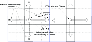
Furthermore, we observe the following about the alternate scheme:
-
The th-tier interferer nodes are located at a distance of at least from the destination cluster, for .
-
A 25-TDMA scheme is used, so there is one active transmit relay-cluster among 25 clusters of size (the optimal cluster size).
In the following we quantify the interference in each cluster, and demonstrate that degrees of freedom are achievable in the proposed MIMO communication.
The derivation of the maximum amount of interference for the nodes of each receive cluster follows the same lines as (7), and we only replace the spatial separation of with . It can be easily verified that as before, by replacing this new value, the term inside the summation in (7) approaches a constant, and we can upper-bound the inter-cluster interference as for a constant . This leads to the following two lemmas, which were developed in [6] for a dense network but here we show to hold in the extended network under consideration. The proofs are given in the appendix.
Lemma 4
The achieved mutual information between any pair of transmit-receive relay-clusters during the multi-hop phase, and hence , grows at least linearly with .
Lemma 5
There exists a strategy to encode the observation at each node in the final receive-cluster at a fixed rate, , and still maintain the above linear growth of the mutual information for the quantized MIMO channel.
We now summarize the overall required time to complete this phase in the following proposition:
Proposition 3
The total required time to complete the inter-cluster communication phase is .
Proof:
During each step of the proposed 25-TDMA communication, of the clusters act as active sources. Due to Lemmas 4 and 5, the full spatial multiplexing is achieved in this phase, and at any point along the route the rate between immediate adjacent clusters is lower-bounded by the rate between the clusters located two cluster-hops away. Since symbols are sent over each cluster-hop, the communication time between each pair of transmit-receive relay-clusters scales as .
There are cluster-hops between the source and the destination since there are at most a total of squares of size along a horizontal path as well as a vertical path. Therefore, the end-to-end communication time is upper-bounded by . We also should note that there are nodes inside each cluster. Therefore, the total time required to complete the inter-cluster communication is upper-bounded by . ∎
V-C Message Decoding at the Destination
Let represent the interference power at any destination node during this phase. Following our analysis of interference in (7), and due to the 9-TDMA used to select the active th-level clusters, it is clear that . Hence, the achievable communication rate can be written as
where is the square amplitude of the channel between any node in the cluster and the destination , and is the vector of the received message at the destination.
In order to derive a lower-bound on , we assume that the destination is located on one of the corners of the cluster. In a regular network, this choice results in the smallest value for . To evaluate this term, we use Fig. 2(a) as an example. We consider the node located at the upper-right corner. There are 3 nodes in 3 squares which are adjacent to the square containing this node, each located at a distance of at most from the destination. We call these nodes 1st-tier nodes. Likewise, the 2nd-tier consists of 5 nodes with a distance of at most from the destination. Generalizing the idea, it can be verified that in the th tier, there are nodes of distance at least from the destination . Therefore, we have
where is the Riemann-Zeta function. Hence, is a constant and does not scale with the cluster size. This leads to the following conclusion.
Proposition 4
The required time to complete the message decoding phase is .
Proof:
Based on the result of Lemma 5 each node quantizes its observation of the message using a constant, , bits and the communication rate is lower-bounded by a constant, therefore, the required time to finish each MISO transmission to deliver bits is . Because of the 9-TDMA scheme and the fact that there are destination nodes inside each cluster, the overall required time to complete this step is . ∎
V-D Constructive Lower-Bound on the Capacity
The lower bound on the capacity can now be derived, since we know the scaling behavior of the required time for each phase and the total number of bits transmitted in the network. As , the total required time to finish transmitting a packet using the proposed communication scheme is
Therefore, since each node sends a packet of length and there are nodes in the network, the overall network capacity can be written as
Note that since we are interested in the scaling behavior of the capacity, our goal is to find for some function . By letting , we find the optimal , for some constant . Substituting this into , we have the following main result.
Theorem 1
Assuming , the achievable network throughput for all source-destination pairs using the proposed algorithm is with a power scaling of for some constant .
VI Scaling Laws for Random Networks
VI-A Random Network with Unit Node Density
In this section, we assume that nodes are distributed uniformly randomly in the area with unit density and study the achievable network throughput. The communication algorithm is in nature the same as that of the case for a regular network. We explain the minor differences where appropriate and derive the asymptotic throughput for this random network.
VI-A1 Communication inside Squares
In a random network, we cannot guarantee that each unit area contains exactly one node. Hence, instead of squares with unit area, we study squares of area , for , and find a tight bound on the number of nodes inside each such square as stated in Lemma 6. We then apply the results of Section V to this setting.
Lemma 6
For all squares of area , , indexed as , the number of nodes, , inside each square is in the interval , , with probability .
The proof is given in the appendix.
We assume that instead of packets of length , the nodes transmit their messages in packets of length bits for the case of random networks. Here represents the optimal number of squares with area inside the cluster. For this topology, we add an extra phase before each 1st-level cast of the intra-cluster communication in order to distribute each node’s message inside the squares of area .
In this phase, each source node transmits a different sub-block of bits to each of the other nodes inside the square. As before, a 9-TDMA scheme is used to determine the set of active squares. Within each active square of area , only one node sends its message at a given time. Therefore, using a similar analysis to (7), it is straightforward to deduce that the interference tends to 0 inside each square and the communication is limited by noise as .
The distance between any pair of nodes located inside each square is at most . Therefore, the communication rate between each pair is lower-bounded by as . Hence, each node can distribute its packet of length bits among its neighbor nodes in the square in seconds for some constant .
VI-A2 Modified Three-phase Scheme and Capacity Evaluation
The same scheme for intra-cluster communication can now be used with a slight modification, such that instead of having one node in each 0th-level cluster, we now have nodes. In order to find the topology leading to the lowest communication rate, we follow the lines of analysis in Section V-A with the slight difference that during the th iteration, we assume all nodes inside each square of area are co-located at the worst-case point, whose location can be found similarly to how Lemma 2 is derived. In order to derive the lower-bound on the communication rate in this case, we also need to consider the fact that the distance between any two nodes is multiplied by compared to the case in a regular network. It is clear that since the square area grows with , the resulting interference, , during the th iteration obeys .
Applying the above changes to the number of nodes in each square and their relative distance, the result of Proposition 1 is modified to the following.
Proposition 5
In the random network with unit node density, as ,
Hence, if , then
otherwise,
Defining similarly to in Section V-A, we have the required time to finish the th iteration
The first term in the above summation accounts for the required time to propagate the message inside the squares of area . The second term has the same structure as (9). The last inequality follows from induction and the fact that . From this, we obtain the following conclusion.
Proposition 6
The total time required to complete the intra-cluster communication phase in a random network with unit node density is .
Proof:
Along the same line as (10), and by replacing , it is clear that
Since there are nodes inside each cluster, the overall required time to finish this phase is . ∎
The inter-cluster communication and message-decoding phases are almost identical to the regular network case. At the beginning of the inter-cluster communication, within each cluster of size there are nodes. By using Lemmas 4 and 5, it is clear that the achieved capacity in this phase, , grows at least linearly with and the power constraint in this phase is . Hence, we have
Proposition 7
In the random network with unit node density the total required time to complete inter-cluster communication is .
The required time for decoding at the destination cluster follows from the analysis in Section V-C. It can be shown that we can maintain a constant rate of communication, and therefore the required time to complete MISO communication is . Hence, we have
Proposition 8
In the random network with unit node density the total required time to complete the message decoding phase is .
We can now write the total communication time for a random network as
and the network throughput is given by
To maximize , we set . Therefore, the optimal cluster size is , for a constant . Hence, we obtain the following main result for a random network.
Theorem 2
In the random network with unit node density assuming , the achievable network throughput for all source-destination pairs using the proposed algorithm is with a required power scaling of for some constant .
VI-B Random Network with Density
We can use a similar algorithm as Section VI-A to find constructive lower-bounds on the capacity scaling behavior of an extended network with a node density .
Lemma 7
For all squares of unit area indexed as , if , the number of nodes, , inside the square is in the interval , , with probability .
Proof:
The proof is similar to the proof of Lemma 6. The probability of lying in a square of unit area equals . Here, represents the number of nodes inside a unit square and we have . Using the upper-bound version of the bound we have, . If we choose for , with probability 1 the number of nodes inside all unit squares follows , and . ∎
As opposed to squares of area in the previous section, the base squares of unit area are considered and the nodes transmit their messages in packets of length . By employing the 9-TDMA communication, interference tends to a constant inside each unit square. The distance between any pair of nodes located inside each unit square, is at most . Therefore, a constant communication rate between each pair is achieved inside the square, and each node can transmit bits to its neighbor nodes in seconds for some constant
We replicate the analysis done in (7) and consider the fact that instead of nodes, the th-level cluster consists of nodes. Therefore, by modifying (7) we can show that the interference during the th iteration obeys
| (11) |
If (high interference regime) the rate of the th-level cast scales as , and if , since the rate scales as .
In the th iteration, a -level cluster transmits bits to one of its neighbors, and using the same line of reasoning that we used to derive in Section VI-A, we have
Proposition 9
The total time required to finish the intra-cluster communication phase in a random network with density is .
Proof:
Along the same line as (9), and by replacing , it can be deduced that . There are nodes inside each cluster of size , therefore, the overall required time to finish this phase is . ∎
The achieved capacity in the inter-cluster phase, , grows at least linearly with and the power constraint in this phase is .
Proposition 10
The total required time to finish the inter-cluster communication (routing) in a random network with node density is .
Proof:
The proof follows from the proof of Proposition 3 and the fact that there are nodes in each cluster instead of nodes. ∎
To evaluate the required time for message decoding at the destination cluster, it can be easily shown that in the MISO analysis, the lower-bound on the sum equals , since in the worst case scenario, in tier all the nodes are located at the distance from the destination.
For the interference analysis, considering (11) and replacing , we again have two paradigms. If , , otherwise . The rate of communication in the first case obeys
and in the second case it obeys
In both cases, . Hence,
Proposition 11
The total required time to finish the message decoding phase in a random network with node density is .
We can now write the total communication time for this setting as . The network throughput in this case follows
To maximize the throughput we set . Therefore, the cluster size in this case can be expressed as . The optimal cluster size decreases by increasing the node density, which is expected since a cluster of area has more nodes compared to the case of regular networks due to higher node density and as a result the same degrees of freedom can be achieved in a smaller area.
Theorem 3
The achievable network throughput assuming for all possible source-destination pairings and using the proposed algorithm for random networks with follows with a required power scaling of .
VII Conclusion
In this paper we study the communication among nodes in an extended network, where both signal interference and power decay are limiting factors of the network capacity. Through the asymptotic analysis of a proposed three-phase communication scheme, we quantify how the appropriate combination of node cooperation, in the form of distributed virtual antenna arrays, and multi-hop message relaying, among optimally sized clusters of nodes, can increase the network throughput. The use of spatially separated clusters of distributed antennas brings benefits from both the spatial multiplexing gain of MIMO and the mitigation of interference. At the same time, multi-hop communication among the clusters allows significant power scaling advantage over direct MIMO communication between the source and destination clusters. The derived asymptotic throughput of the proposed communication scheme provides a constructive lower bound to the capacity of an extended network with node cooperation.
Appendix A Proof of Lemma 1
From linear algebra it is well known that the derivative of the determinant of a square matrix, , can be written as for an invertible matrix . Using Taylor series expansion, we have , for small and matrix . The last term is obtained by computing the second order derivative of the determinant. Therefore, we can simplify the argument of the function in the given capacity expression as follows, . Since , we can choose .
Appendix B Proof of Lemma 2
There are transmitter nodes (at ) and receiver nodes (at ), and horizontal locations for the nodes to be placed. Therefore, we need to choose one of the indices on each side and remove it from the set of node locations. To minimize , we should choose the index on the transmit side and on the receive side for which the sums and are maximized, and remove them from the index set.
The index chosen to be removed from the transmitter set is the one which results in the largest number of receiver indices with small vertical distance from node . It is possible for at most two distinct nodes with indices in the receive-cluster to have a common distance from a node with index in the transmit-cluster. Choosing such that or , results in having a node which has the largest number of receiver nodes with small distances from it. (For example, this is equivalent to choosing or in Fig. 1 (b)). Let’s set . By symmetry, the removed index in the receive-cluster equals to one of the above given indices. Choosing instead of results in removing channels with larger amplitudes from . Swapping the values of and results in the same achievable rate.
Appendix C Proof of Lemma 3
We evaluate . For , the second term in (LABEL:hd) approaches 0 and we have . Using (6), for , . Therefore, we have , where the last equality follows from the fact that in limit tends to a constant, , and can be written in terms of the Riemann-Zeta function with a constant argument. Therefore, the final result holds for some constant .
Appendix D Proof of Lemma 4
This result is in essence similar to Lemma 4.3 of [6]. We only need to establish a few facts here. The minimum distance between a pair of nodes, and , is , and the maximum of such a distance equals . Furthermore, the distance between the center of transmit- and receive-clusters equals . Therefore, follows , and hence, , for . By treating the interference as a source of noise, and based on our assumption that , the mutual information between the two clusters can be written as
where , , and are respectively the corresponding input, output, and channel matrices, is a matrix with elements , and is a constant. The rest of the problem has the same structure as Lemma 4.3 in [6] and the linearity of the rate growth with the number of distributed antennas follows from there.
Appendix E Proof of Lemma 5
The proof follows from Lemma 4.4 of [6] and the fact that the received power at any node in the receive-cluster follows , which is a constant.
Appendix F Proof of Lemma 6
Assuming that there are nodes distributed uniformly over , for each node we define the random variable to be equal to 1 if it lies in a given square with area and 0 otherwise. Clearly, . Using Chernoff’s bounds for binomial random variable , which represents the number of nodes inside a square, we have , and, furthermore, , where . To guarantee that the number of nodes inside all the squares obeys these inequalities, we use the union bound of the probabilities. It directly follows that if , with probability 1 the number of nodes inside all squares of area follows , and .
References
- [1] P. Gupta and P. Kumar, “The capacity of wireless networks,” IEEE Transactions on Information Theory, vol. 46, pp. 388–404, March 2000.
- [2] A. Jovicic, P. Viswanath, and S. R. Kulkarni, “Upper bounds to transport capacity of wireless networks,” IEEE Transactions on Information Theory, vol. 50, pp. 2555–2565, November 2004.
- [3] O. Leveque and I. E. Talatar, “Information-theoretic upper bounds on the capacity of large extended ad hoc wireless networks,” IEEE Transactions on Information Theory, vol. 51, March 2005.
- [4] L. L. Xie and P. R. Kumar, “On the path-loss attenuation regime for positive cost and linear scaling of transport capacity in wireless networks,” Joint Special Issue of IEEE Transactions on Information Theory and IEEE/ACM Transactions on Networking on Networking and Information Theory, vol. 52, pp. 2313–2328, June 2006.
- [5] D. Tse and P. Viswanath, Fundamentals of Wireless Communication. Cambridge University Press, May 2005.
- [6] A. Ozgur, O. Leveque, and D. Tse, “Hierarchical cooperation achieves linear capacity scaling in ad-hoc networks.” in Proc. IEEE Infocom 2007 also in the IEEE Transactions on Information Theory, December 2007.
- [7] S. Vakil and B. Liang, “Effect of joint cooperation and multi-hopping on the capacity of wireless networks,” in Proc. IEEE Communications Society Conference on Sensor, Mesh and Ad Hoc Communications and Networks (SECON), June 2008.
- [8] L. L. Xie and P. R. Kumar, “A network information theory for wireless communications: Scaling laws and optimal operation,” IEEE Transactions on Information Theory, vol. 50, pp. 748–767, May 2004.
- [9] S. Toumpis and A. J. Goldsmith, “Large wireless networks under fading, mobility, and delay constraints,” in Proc. IEEE Infocom, March 2004.
- [10] M. Franceschetti, O. Dousse, D. N. C. Tse, and P. Thiran, “Closing the gap in the capacity of wireless networks via percolation theory,” IEEE Transactions on Information Theory, vol. 53, pp. 1009–1018, March 2007.
- [11] M. Gastpar and M. Vetterli, “On the capacity of wireless networks: the relay case,” in Proc. IEEE Infocom, June 2002.
- [12] S. Aeron and V. Saligrama, “Wireless ad hoc networks: Strategies and scaling laws for the fixed SNR regime,” IEEE Transactions on Information Theory, vol. 53, pp. 2044–2059, June 2007.
- [13] I. E. Telatar, “Capacity of multi-antenna Gaussian channels,” European Transactions on Telecommunication, vol. 10, pp. 585–595, November-December 1999.
| Sam Vakil received the B.Sc. degree in Electrical Engineering from Sharif University of Technology in Tehran, Iran, in 2002 and the M.Eng degree in Electrical Engineering from McGill University in Montreal, Canada, in 2004. He is now pursuing the Ph.D. degree in Electrical & Computer Engineering at the University of Toronto. His current research interest includes the design and analysis of cooperative communication protocols for wireless ad-hoc and wireless networks. |
| Ben Liang received honors simultaneous B.Sc. (valedictorian) and M.Sc. degrees in electrical engineering from Polytechnic University in Brooklyn, New York, in 1997 and the Ph.D. degree in electrical engineering with computer science minor from Cornell University in Ithaca, New York, in 2001. In the 2001 - 2002 academic year, he was a visiting lecturer and post-doctoral research associate at Cornell University. He joined the Department of Electrical and Computer Engineering at the University of Toronto in 2002, where he is now an Associate Professor. His current research interests are in mobile networking and multimedia systems. He won an Intel Foundation Graduate Fellowship in 2000 toward the completion of his Ph.D. dissertation and an Early Researcher Award (ERA) given by the Ontario Ministry of Research and Innovation in 2007. He was a co-author of the Best Paper Award at the IFIP Networking conference in 2005 and the Runner-up Best Paper Award at the International Conference on Quality of Service in Heterogeneous Wired/Wireless Networks in 2006. He is an editor for the IEEE Transactions on Wireless Communications and an associate editor for the Wiley Security and Communication Networks journal. He serves on the organizational and technical committees of a number of conferences each year. He is a senior member of IEEE and a member of ACM and Tau Beta Pi. |