Carrier relaxation in Si/SiO2 quantum dots
Abstract
Carrier relaxation due to both optical and nonradiative intraband transitions in silicon quantum dots (QDs) in SiO2 has been considered. Interaction of confined holes with optical phonons has been studied. The Huang-Rhys factor is calculated for such transitions. The probability of intraband transition of a confined hole emitting several optical phonons is estimated.
I Introduction
The system of silicon quantum dots in silicon oxide matrix has been of great interest during the past decade. Apart from increasing excitation rate of implanted erbium ions Kenyon_PQE_2002 Si nanocrystals can be used as a light source Pavesi_Nature_2000 or a photon cutting medium in photovoltaics applications Timmerman_Nature_2008 . The theory of single-particle states in spherical Si/SiO2 quantum dots has been recently developed Moskalenko_PRB_2007 . It was shown that most of the gaps between the calculated levels appeared to be large enough to suppress single-phonon relaxation processes in QD with diameter in the range nm. Here we present the calculation of relaxation probabilities for confined electrons and holes. Both — optical and nonradiative — intraband transitions are considered. Multiphonon intraband transitions of valence-band holes are due to their interaction with optical phonons via the deformation potential. This mechanism of carrier-phonon coupling is only efficient for valence-band holes while for conduction-band electrons it is forbidden by the crystal symmetry BirPikus_book .
Values of the Huang-Rhys parameter are calculated, and the probabilities of the transitions are estimated.
II Carriers confined in spherical Si quantum dots
Here we use the effective mass approach to spherical silicon nanocrystals developed in Moskalenko_PRB_2007 . The spin-orbit interaction is neglected in the consideration. The details of the approximation are given below.
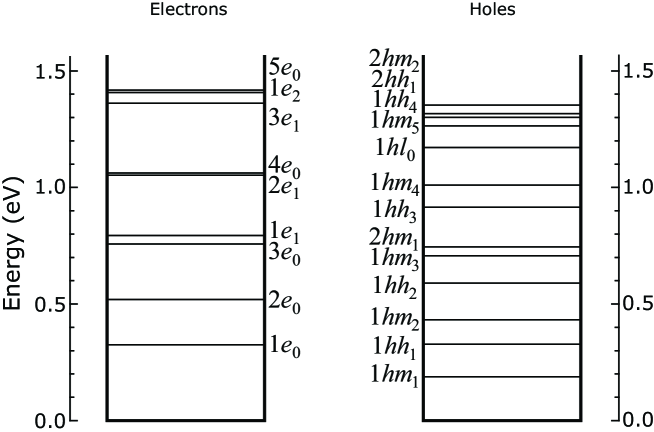
Electron envelope functions are found as a result of a numerical solution to the Schrödinger equation after separating the angular part ( can be any integer number) as there is a strong anisotropy of the electron effective mass. Due to the conduction band symmetry the electron states are sixfold degenerate for m=0 and 12 times degenerate for , as two opposite values correspond to the same energy. So the states are marked with where the letter shows that it is an electron state, is the main quantum number which shows the order of the energy level for given . For example, the ground state is marked as , which means that this is the first electron state with .
The hole states are characterized by the total angular momentum and parity. The states with the parity are the heavy hole () states while the states with the parity are contributed by both the light and the heavy hole states (mixed hole states: ) with the only exception for when the hole states are only contributed by the light holes (). The hole states are described by the main quantum number followed by the abbreviation , or and the subscript denoting the total angular momentum . For example, the hole state with the lowest energy is of the mixed type — .
Calculated electron and hole energy levels are shown in Fig. 1.
III Optical intraband transitions of confined carriers
Previously, the oscillator strengths were calculated for electrons in Si QD Allan_PRB_2002 . However, the tight-binding model used there greatly overestimates the carrier quantization energies if applied to Si QD embedded into SiO2. Here we use our theory developed for carriers confined in Si/SiO2 QD, giving much better agreement with the experiments on this system, and produce calculations for intraband transitions of holes as well.
The spontaneous emission rate is given by the relation between Einstein coefficients Goupalov_PRB_2003 :
| (1) |
Here is the effective refractive index of the media given by the formulae below Thraendhardt_PRB_2002 :
| (2) |
| (3) |
III.1 Electrons
The calculation of the electron optical matrix elements in Eq. (1) is produced numerically. The resulting times of radiative intraband transitions are shown in Table 1 for QD diameter 3.1 nm. An empty space in the table means that the corresponding transition is either forbidden by symmetry or is too slow.
| From To | ||||||||
|---|---|---|---|---|---|---|---|---|
| 2.4 s | — | — | — | — | — | — | — | |
| 0.71 s | — | — | — | — | — | — | ||
| 0.04 s | — | — | — | — | — | |||
| 0.03 s | 0.32 s | — | — | — | — | |||
| 19.6 s | — | — | — | |||||
| 0.8 s | 0.03 s | — | — | |||||
| 4.4 s | — | |||||||
| 0.17 s |
III.2 Holes
Due to the combination of spherical QD shape and spherical approximation to the hole states, there are strong selection rules for optical intraband transitions of holes, which are listed in Table 2.
The times of radiative intraband transitions of holes are given in Table 3.
| From To | ||||||||
| 1.2 s | — | — | — | — | — | — | — | |
| 1.3 s | — | — | — | — | — | — | ||
| 1.1 s | 20 s | — | — | — | — | — | ||
| 0.55 s | — | — | — | — | ||||
| 0.12 s | 0.41 s | — | — | — | ||||
| 0.38 s | 9.9 s | — | — | |||||
| 0.33 s | — | |||||||
| 6.0 ns | 0.56 s |
IV Confined hole energy relaxation due to multiphonon transitions
Although most of the gaps between the calculated energy levels in the valence band appear to be large enough ( meV) to suppress intraband relaxation processes assisted by emission of a single phonon in QDs with diameter in the range of nm. However, nonradiative transitions in which the valence-band hole emits several optical phonons (energy of optical phonon in Si is about 60 meV) are possible. The rate of such multiphonon intraband energy relaxation is governed by the Huang-Rhys factor HuangRhys ; Abakumov_book ; Goupalov_PRB_2005 . In case of the rate of transition assisted by emission of phonons, , is proportional to the factor of the order of compared to the single-phonon transition rate. Below we present a calculation of the Huang-Rhys factor for intraband transitions of valence-band holes confined in Si/SiO2 nanocrystals.
In non-polar Si interaction of phonons with holes is determined by the deformation potential. Interaction of electrons with optical phonons via the deformation potential is forbidden by the crystal symmetry. Since optical phonons in Si are almost dispersionless, the system under study can be described by multi-mode Huang-Rhys model, similar to the one-mode model Abakumov_book ; Goupalov_PRB_2005 .
We consider two hole levels of size quantization and in the QD potential with energies , () interacting with optical phonons characterized by frequency , wavevector and polarisation . The Hamiltonian of the hole interaction with optical phonons in Si is given by BirPikus_book :
| (4) |
where , is the lattice constant, is the interaction constant. The value of in silicon confirmed by experimental data is 27 eV Cardona_PRB_1987 ; Cardona_PSSB_1984 . But when spin-orbit interaction is neglected (that is the approximation we use) and holes are characterized by momentum , one can easily find that the value of should be multiplied by 3 (compared to the case of ). So eV is used in our consideration.
The continuous field of the relative atomic displacement for a given bulk phonon mode is
| (5) |
where is the reduced mass density, and the polarization vectors can be chosen to be purely real. It is convinient to introduce following matrix elements:
| (6) |
Electron-phonon interaction induces polaron shifts to energy levels under consideration. Taking these shifts into account, the number of phonons emitted is given by
The Huang-Rhys factor is given by
| (7) |
The calculated values of for the transitions between the four lowest hole levels are presented in Fig. 2.
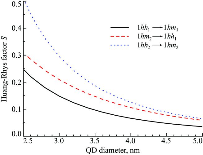
The phonon factor corresponding to the number of phonons that should be emitted for transitions between neighboring levels () is of the order of Prokofiev_JoL_2006 . Keeping in mind that the characteristic time of the one-phonon transition is 1 ps, we conclude that the rate of multiphonon energy relaxation of hot holes is of the order of s-1.
V Conclusions
For spherical silicon nanocrystals in SiO2 under consideration the estimated rate of multi-phonon hole transitions ( s-1) is higher than both electron and hole optical intraband transitions rates, lying in the range of s-1. All the intraband relaxation mechanisms considered above are much faster than optical recombination of confined carriers (whose rate is not higher than s-1 Moskalenko_PRB_2007 ). Thus, when considering radiative recombination of confined excitons, one may assume most of the carriers to be in the ground states of QD.
This work was supported in part by DoD under contract No. W912HZ-06-C-0057.
References
- (1) A. J. Kenyon, Prog. Quantum Electron. 26, 225 (2002).
- (2) L. Pavesi, L. Dal Negro, C. Mazzoleni, G. Franzo, F. Priolo, Nature 408, 440 (2000).
- (3) D. Timmerman, I. Izeddin, P. Stallinga, I. N. Yassievich, T. Gregorkiewicz, Nature Photonics 2, 105 (2008).
- (4) A. S. Moskalenko, J. Berakdar, A. A. Prokofiev, I. N. Yassievich, Phys. Rev. B 76, 085427 (2007).
- (5) G. L. Bir and G. E. Pikus, Symmetry and Strain-Induced Effects in Semiconductors (Nauka, Moscow 1972).
- (6) G. Allan, C. Delerue, Phys. Rev. B 66, 233303 (2002).
- (7) S. V. Goupalov, Phys. Rev. B 68, 125311 (2003).
- (8) A. Thrändhardt, C. Ell, G. Khitrova, and H. M. Gibbs, Phys. Rev. B 65, 035327 (2002).
- (9) K. Huang and A. Rhys, Proc. Roy. Soc. London A 204, 406 (1950); K. Huang, Scientia Sinica 24, 27 (1981).
- (10) V. N. Abakumov, V. I. Perel, and I. N. Yassievich, in Nonradiative Recombination in Semiconductors, edited by V. M. Agranovich and A. A. Maradudin, Modern Problems in Condensed Matter Sciences Vol. 33, Elsevier, Amsterdam, 1991.
- (11) S. V. Goupalov, Phys. Rev. B 72, 073301 (2005).
- (12) L. Brey, N. E. Christensen, and M. Cardona, Phys. Rev. B 36, 2638 (1987).
- (13) A. Blacha, H. Presting, and M. Cardona, Phys. Status Solidi B 126, 11 (1984).
- (14) A. A. Prokofiev, A. S. Moskalenko, I. N. Yassievich, J. of Lumin. 121, 222 (2006).