Enhancement of evanescent waves inside media with extreme optical anisotropy
Abstract
Significant enhancement of evanescent spatial harmonics inside the slabs of media with extreme optical anisotropy is revealed. This phenomenon results from the pumping of standing waves and has the feature of being weakly sensitive to the material losses. Such characteristics may enable subwavelength imaging at considerable distances away from the objects.
pacs:
78.20.Ci, 42.70.Qs, 42.25.Fx, 73.20.MfModern nanofabrication techniques have brought major breakthroughs in the area of photonics and nanotechnology and make it possible to manufacture structures with details less than a few nanometers. Such advances in manufacturing technology lead to further miniaturization of optical systems and stimulate increasing interest in the development of devices capable of manipulating electromagnetic waves at the subwavelength scale: e.g. optical waveguides with their cross-sections much smaller than the wavelength, structures enabling nanoscale concentration of light, superlenses with resolutions below the diffraction limit, etc. All these devices are capable of manipulating the near fields and they dramatically differ from conventional optical components that mostly deal with the propagating waves. In this letter we report a novel means to enhance evanescent waves which can overcome a major constraint of optical near field devices suffering from the rapid spatial decay of evanescent harmonics. One possible application is the performance improvement of near-field scanning optical microscopy. Currently, this technique suffers from the limitation that the objects of interest have to be located close enough to the probe of the scanner, otherwise, the near field of the object which contains subwavelength details will be too weak to be detected. The use of the proposed evanescent wave enhancement effect will allow the near-field scanners to operate with the objects located at significant distances. This important advance opens the door to a variety of possible applications, including the case when physical access to the near field region of an object is not feasible. For example, sub-surface capillary vessels in biological systems can potentially be accessed using non-pervasive methods by exploiting the near-field of light.
It is known that evanescent waves can be enhanced by the use of resonant excitation of surface plasmons. Thin slabs of noble metals can “amplify” evanescent harmonics within frequency ranges of their plasmonic resonances Fang et al. (2005). Theoretically, significant “amplification” can be provided by slabs of metamaterials with negative permittivity and permeability, also known as perfect lenses Pendry (2000). However, the practical application of the perfect lens concept has been stalled by the limitations of loss and bandwidth Jacob et al. (2006) and the creation of metamaterials in the optical domain remains a major challenge Shalaev (2007). In this letter, we propose a conceptually different approach to enable the significant enhancement of evanescent harmonics. Its principle is based on pumping of standing waves inside a slab of extremely anisotropic medium and features weak sensitivity to material losses.
Let us consider an uniaxial dielectric medium with permittivity dyadic of the form:
| (1) |
The dispersion equation for extraordinary waves in such medium reads:
| (2) |
where are the components of wave vector , is the frequency of operation and is the speed of light in the vacuum.
If the medium has extreme optical anisotropy, that means , then (2) has the following solution:
| (3) |
Therefore, all extraordinary waves of the medium with extreme optical anisotropy are dispersionless: they travel ultimately along the direction of anisotropy with a fixed phase velocity irrespectively of their transverse variation. Note, that must not necessarily be real. It can be a complex number with a large absolute value. The imaginary part of representing losses has no influence on the properties of waves in the medium.
Basically, a whole class of dielectrics with extreme optical anisotropy can be accurately described by permittivity dyadic in the form
| (4) |
The infinite value appearing in (4) should not be treated as something exceptional or unusual. The corresponding material relations read as , and . This actually means that the medium is perfectly conducting along -direction.
The latter fact gives a hint how media with extreme optical anisotropy can be created artificially. An array of parallel metallic wires, also known as a wire medium Belov et al. (2003), will provide necessary properties at frequencies up to the infrared band Silveirinha (2006). In the visible frequency range, one of the options may be a layered-metal dielectric structure Belov and Hao (2006) which has an effective permittivity in the form (4).
Let a slab with thickness of medium with extreme optical anisotropy in a direction perpendicular to the interfaces be excited by an obliquely incident -polarized plane wave with the tangential component of the wave vector . The time dependence is . The total magnetic field can be written in the form:
| (5) |
where is the coordinate along anisotropy axis, is the wave number of free space, is the amplitude of the incident wave, and are the reflection and transmission coefficients, and are the amplitudes of waves inside of the slab traveling in forward and backward directions, respectively. The values of these coefficients can be easily obtained by matching boundary conditions at the interfaces:
where
If the thickness of the slab fulfills the Fabry-Perot resonance condition then
Note, that under this condition the slab operates in the canalization regime Belov et al. (2005, 2006); Silveirinha et al. (2007); Belov and Hao (2006) as a perfect transmission device: it does not produce any reflections and perfectly transmits arbitrary field distributions from the front- to back-interface. This occurs since in the case of media with extreme optical anisotropy the Fabry-Perot condition is verified simultaneously for all spatial harmonics. This extraordinary property is justified by the fact that all waves travel across the slab with the fixed phase velocity irrespectively of their transverse wave vectors (3). Thus, the total electrical length of the slab remains the same for all possible angles of incidence.
The effect is observed in the slabs with their thicknesses equal to an integer number of half-wavelengths. In the next part of the letter, for simplicity, we only consider slabs of a half-wavelength thickness: .
The magnetic field distribution inside the slab can be written in the following form
| (6) |
For the evanescent part of spatial spectrum () this distribution has the form of a standing wave with amplitude
| (7) |
This amplitude is a growing function of . For high spatial harmonics () it has a nearly linear dependence . This means the higher is, the more rapidly the evanescent wave decays and the higher amplitude of standing wave is excited inside the slab. This fact is illustrated in Fig. 1.
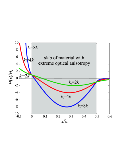
Effectively, this phenomenon can be treated as an increase in the amplitude of the evanescent wave. Such an enhancement is observed only inside the slab, but not outside as in alternative configurations with slabs of materials with negative material parameters Fang et al. (2005); Pendry (2000).
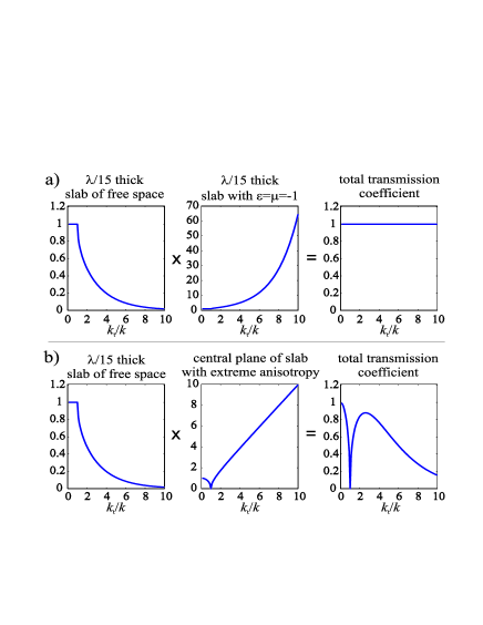
In order to further compare the enhancement capabilities of these two alternative approaches, the transmission coefficients for slabs formed by a medium with and by a medium with extreme optical anisotropy are presented in Fig. 2 as functions of transverse wave vector. In the case of metamaterial slab, the coefficient describes the transmission from the front- to back-interface. Whereas, for the slab of medium with extreme optical anisotropy the transmission coefficient is calculated from the front-interface to the central plane. According to (6) it is equal to:
| (8) |
The growing exponential and nearly linear dependencies for transmission coefficients under comparison are clearly visible in Fig. 2. The slab of metamaterial is chosen to have a thickness equal to which is able to completely compensate for the decay of evanescent waves in free space at a distance. In the case of slab formed by medium with extreme optical anisotropy, the total transmission coefficient does not equal to unity for any transverse wave vector in contrast to the previous case. Essentially, this occurs since the linear enhancement can not completely compensate the exponential decay of evanescent waves. However, this enhancement significantly improves transmission characteristic of the free space slab. Therefore, the slabs of media with extreme optical anisotropy can be successfully used for subwavelength imaging purposes.
The proposed imaging technique can be viewed as an improvement of the canalization regime Belov et al. (2005, 2006); Silveirinha et al. (2007); Belov and Hao (2006) which enables a transmission of images with subwavelength resolution from the front- to back-interface of a slab formed by medium with extreme optical anisotropy. Without any change in the structure, the imaging device can operate with sources located at certain distance from the slab, but the image in this case has to be detected inside the medium.
The imaging devices are not perfect by any means since they introduce certain distortions because their transmission coefficient is not equal to unity for the entire spectrum of spatial harmonics. However, the form of this distortion is known: it is given by formula (8). Thus, the distorted image captured inside of the proposed device can be processed and the original distribution can be restored. For this purpose, it is enough to expand the image into spatial spectrum using a 2D Fourier transform, to divide it by the transmission coefficient and to perform an inverse 2D Fourier transform. Within the range of spatial frequencies corresponding to large enough transmission, this procedure leads to perfect restoration of the spectrum of the original image. The remainder of the spatial information has to be filtered since the division by small transmission coefficient leads to significant enhancement of signal to noise ratio.
In conclusion, the phenomenon of evanescent waves enhancement originated from resonant pumping of standing waves is observed inside the slabs of media with extreme optical anisotropy. This enables subwavelength imaging of objects placed at considerable distances away from the slab.
References
- Fang et al. (2005) N. Fang, H. Lee, C. Sun, and X. Zhang, Science 308, 534 (2005).
- Pendry (2000) J. Pendry, Phys. Rev. Lett. 85, 3966 (2000).
- Jacob et al. (2006) Z. Jacob, L. V. Alekseyev, and E. Narimanov, Optics Express 14, 8247 (2006).
- Shalaev (2007) V. M. Shalaev, Nature Photonics 1, 41 (2007).
- Belov et al. (2003) P. Belov, R. Marques, S. Maslovski, I. Nefedov, M. Silverinha, C. Simovski, and S. Tretyakov, Phys. Rev. B 67, 113103 (2003).
- Silveirinha (2006) M. Silveirinha, Phys. Rev. E 73, 046612 (2006).
- Belov and Hao (2006) P. Belov and Y. Hao, Phys. Rev. B 73, 113110 (2006).
- Belov et al. (2005) P. A. Belov, C. R. Simovski, and P. Ikonen, Phys. Rev. B. 71, 193105 (2005).
- Belov et al. (2006) P. A. Belov, Y. Hao, and S. Sudhakaran, Phys. Rev. B 73, 033108 (2006).
- Silveirinha et al. (2007) M. Silveirinha, P. Belov, and C. Simovski, Phys. Rev. B 75, 035108 (2007).