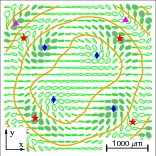
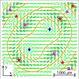
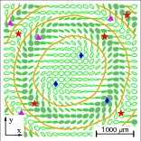
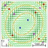
Topological events in polarization resolved angular patterns of nematic liquid crystal cells at varying ellipticity of incident wave

Alexei D. Kiselev kiselev@iop.kiev.ua    Roman G. Vovk roman.vovk@gmail.com Institute of Physics of National Academy of Sciences of Ukraine, prospekt Nauki 46, 03028 Kyïv, Ukraine
Abstract

We study the angular structure of polarization of light transmitted through a nematic liquid crystal (NLC) cell by analyzing the polarization state as a function of the incidence angles and the polarization of the incident wave. The polarization resolved angular (conoscopic) patterns emerging after the NLC cell illuminated by the convergent light beam are described in terms of the polarization singularities such as C-points (points of circular polarization) and L-lines (lines of linear polarization). For the homeotropically aligned cell, the Stokes polarimetry technique is used to measure the polarization resolved conoscopic patterns at different values of the ellipticity of the incident light, ϵell(inc)superscriptsubscriptitalic-ϵellinc\epsilon_{\mathrm{ell}}^{(\mathrm{inc})}. impinging onto the cell. Using the exact analytical expressions for the transfer matrix we show that variations of the ellipticity, ϵell(inc)superscriptsubscriptitalic-ϵellinc\epsilon_{\mathrm{ell}}^{(\mathrm{inc})}, induce transformations of the angular pattern exhibiting the effect of avoided L-line crossings and characterized by topological events such as creation and annihilation of the C-points. The predictions of the theory are found to be in good agreement with the experimental results.

polarization of light; nematic liquid crystal; polarization singularities
pacs:
45.25.Ja, 78.20.Fm, 42.70.Df, 42.25.Bs

I Introduction

Singularities that represent structurally stable topological defects have long been known to play a pivotal role in condensed matter physics Chaikin and Lubensky (1995). They are of particular importance in determining the properties of systems with a broken continuous symmetry Mermin (1979); Michel (1980); Trebin (1982); Kléman (1984) (for a recent review see, e.g., Ref. Kleman and Friedel (2008)). Topological methods of quantum field and gauge theories have been extensively used to classify the topological defects and to describe transformations of the singularities in ordered media such as superfluids and liquid crystals Salomaa and Volovik (1987); Monastyrsky (1993); Schwarz (1993).

For electromagnetic vector fields, it was originally recognized by Nye Nye (1983); Nye and Hajnal (1987); Nye (1999) that the so-called polarization singularities are the important elements characterizing geometry of the Stokes parameter fields. In particular, the polarization singularities such as the C-points [the points where the light wave is circularly polarized] and the L-lines [the curves along which the polarization is linear] frequently emerge as the characteristic feature of certain polarization state distributions. Over the past two decades these singularities and related issues have been the subject of numerous theoretical, experimental and numerical studies Hajnal (1987a, b, 1990); Freund and Shvartsman (1994); Freund et al. (2002a); Berry and Dennis (2000, 2001); Konukhov and Melnikov (2001); Freund (2002); Freund et al. (2002b); Mokhun et al. (2002); Dennis (2002).

The theory of polarization singularities has also been found to be a useful tool for studying optical properties of anisotropic media. In Ref. Berry and Dennis (2003), it was applied to study the angular dependence of the polarization state of the electric displacement field for plane wave eigenmodes in birefringent dichroic chiral crystals. This analysis was then generalized and extended to a more complicated case of bianisotropic media Berry (2005).

The experimental results and theoretical analysis presented in Refs. Flossmann et al. (2005, 2006) deal with the unfolding of a linearly polarized Laguerre-Gauss (LG01) beam with an on-axis vortex on propagation through a birefringent crystal. It was found that a complicated pattern of polarization singularities is formed as a result of the anisotropy induced symmetry breaking.

In our recent investigation into the two-dimensional angular distributions of the Stokes parameters describing the polarization structure behind the conoscopic images we performed a comprehensive theoretical analysis of the polarization state of the light transmitted through nematic liquid crystal (NLC) cells as a function of the incidence angles Kiselev (2006, 2007). This polarization structure — the so-called polarization resolved angular (conoscopic) pattern — is represented by the field of polarization ellipses and results from the interference of four eigenmodes excited in NLC cells by the plane waves with varying direction of incidence.

Note that NLCs are technologically important materials where the optical anisotropy is determined by the orientational structure which is sensitive to external fields and, in restricted geometries, can also be influenced by changing the boundary conditions de Gennes and Prost (1993); Yeh and Gu (1999); Chigrinov (1999). The conoscopy is widely used as an experimental technique to characterize orientational structures in NLC cells.

For example, this method was employed to detect biaxiality of NLCs Yu and Saupe (1980); Madsen et al. (2004) and to measure the pretilt angle in uniaxial liquid crystal cells Komitov et al. (1984); Brett and Winter (2001). Orientational structures and helix unwinding process in ferroelectric and antiferroelectric smectic liquid crystals were also studied by conoscopy in Refs. Gorecka et al. (1990); Parry-Jones et al. (2002); Suwa et al. (2003).

In this paper we explore both theoretically and experimentally the polarization resolved angular patterns for convergent light beam impinging on the homeotropically aligned NLC cell at varying polarization of the incident wave. The layout of the paper is as follows.

In Sec. II we give experimental details and describe our setup employed to carry out measurements using a suitably modified method of the Stokes polarimetry Soskin et al. (2003, 2004); Flossmann et al. (2005); Vovk et al. (2007).

The problem of light transmission through a uniformly anisotropic NLC cell is considered in Sec. III.1. Using the 4×4444\times 4 matrix formalism we deduce the general expressions relating the evolution matrix to the transmission and reflection matrices. The analytical results are used for analysis of the polarization resolved conoscopic patterns. in Sec. III.2

The patterns emerging after homeotropically aligned NLC cells are treated in Sec. III.3. The polarization ellipse fields are studied as a function of the ellipticity, ϵell(inc)superscriptsubscriptitalic-ϵellinc\epsilon_{\mathrm{ell}}^{(\mathrm{inc})}, and the polarization azimuth, ϕp(inc)superscriptsubscriptitalic-ϕ𝑝inc\phi_{p}^{(\mathrm{inc})}, characterizing the polarization state of the incident wave.

The analytical expressions describing loci of the C-points and L-lines along with the index formula are used to examine rearrangements of the polarization singularities caused by variations of the polarization parameters ϵell(inc)superscriptsubscriptitalic-ϵellinc\epsilon_{\mathrm{ell}}^{(\mathrm{inc})} and ϕp(inc)superscriptsubscriptitalic-ϕ𝑝inc\phi_{p}^{(\mathrm{inc})}.

We find that changing the azimuth results in rotation of the ellipse field as a whole by the angle ϕp(inc)superscriptsubscriptitalic-ϕ𝑝inc\phi_{p}^{(\mathrm{inc})}, whereas the transformations induced by the ellipticity appear to be complicated by the presence of bifurcations leading to creation and annihilation of the C-points. It is shown that the structure of the intersecting L-lines formed at ϵell(inc)=0superscriptsubscriptitalic-ϵellinc0\epsilon_{\mathrm{ell}}^{(\mathrm{inc})}=0 smoothly evolve into a family of the concentric L-circles at |ϵell(inc)|=1superscriptsubscriptitalic-ϵellinc1|\epsilon_{\mathrm{ell}}^{(\mathrm{inc})}|=1. At small values of the ellipticity, the effect of avoided L-line crossings is found to be an important feature of this transition.

Experimentally measured and computed fields of the polarization ellipses are presented in Sec. IV along with discussion and concluding remarks. Mathematical details on the evolution operator of uniformly anisotropic media and related issues are relegated to Appendix A.

Refer to caption
Figure 1: Experimental setup: He-Ne is the laser; L1, L2 and L5 are the collimating lenses; L3 and L4 are the microscope objectives; PH is the pinhole; NLC is the NLC cell; P1 and P2 are the polarizers; W1 and W2 are the quarter wave plates; CCD is the CCD camera. A microscope objective L3 is illuminated with an elliptically polarized and expanded parallel beam of light from a He-Ne laser. The output from a second objective L4 is collected by a CCD camera through the Stokes analyzer.

II Experiment

In our experiments we used the NLC cells of thickness d=110𝑑110d=110 μ𝜇\mumfilled with the nematic liquid crystal mixture E7 from Merk. Two glass substrates were assembled to form a hometropically oriented NLC cell. At the wavelength of light generated by a low power He-Ne laser from Coherent Group with λ=632.8𝜆632.8\lambda=632.8 nm (see Fig. 1), the ordinary and extraordinary refractive indices of the NLC are no=1.5246subscript𝑛𝑜1.5246n_{o}=1.5246 and ne=1.7608subscript𝑛𝑒1.7608n_{e}=1.7608, respectively; the refractive index of the glass substrates is ng=1.5subscript𝑛𝑔1.5n_{g}=1.5.

Figure 1 shows our experimental setup devised to perform the conoscopic measurements using the Stokes polarimetry technique Soskin et al. (2003, 2004); Flossmann et al. (2005); Vovk et al. (2007). Referring to Fig. 1, the cell is irradiated with a convergent light beam formed by the microscope objective of high numerical aperture L3. The input polarizer P1 is combined with the properly oriented quarter wave plate W1 to control the polarization characteristics (the ellipticity and the azimuth of polarization) of a He-Ne laser beam which is expanded and collimated using the lenses L1 and L2. A charge coupled device (CCD) camera collects the output from the microscope objective L4 through the collimating lense L5 and the Stokes analyzer represented by the combination of the quarter wave plate W2 and the polarizer P2.

This optical arrangement therefore collects simultaneously the transmittance of the cell for a range of incident angles. The distribution of the Stokes parameters S0S3subscript𝑆0subscript𝑆3S_{0}\ldots S_{3} describing the state of polarization of the transmitted light can then be obtained by performing the measurements at six different combinations of the quarter wave plate W2 and the analyzer P2 and using the well-known relations Born and Wolf (1980)

S1subscript𝑆1\displaystyle S_{1} =I0I90,absentsubscript𝐼superscript0subscript𝐼superscript90\displaystyle=I_{0^{\circ}}-I_{90^{\circ}}, (1a)
S2subscript𝑆2\displaystyle S_{2} =I45I135,absentsubscript𝐼superscript45subscript𝐼superscript135\displaystyle=I_{45^{\circ}}-I_{135^{\circ}}, (1b)
S3subscript𝑆3\displaystyle S_{3} =IRCPILCP,absentsubscript𝐼RCPsubscript𝐼LCP\displaystyle=I_{\text{RCP}}-I_{\text{LCP}}, (1c)
S0subscript𝑆0\displaystyle S_{0} =S12+S22+S32,absentsuperscriptsubscript𝑆12superscriptsubscript𝑆22superscriptsubscript𝑆32\displaystyle=\sqrt{S_{1}^{2}+S_{2}^{2}+S_{3}^{2}}, (1d)

where I0subscript𝐼superscript0I_{0^{\circ}}, I90subscript𝐼superscript90I_{90^{\circ}}, I45subscript𝐼superscript45I_{45^{\circ}} and I135subscript𝐼superscript135I_{135^{\circ}} are the linearly polarized components (subscript indicates the orientation angle of the analyzer); IRCPsubscript𝐼RCPI_{\text{RCP}} and ILCPsubscript𝐼LCPI_{\text{LCP}} are the right- and left-handed circular polarized components measured in the presence of the quarter wave plate W2.

Geometrically, the distribution of the Stokes parameters measured in the observation plane can be conveniently represented by the two-dimensional field of the polarization ellipses. The geometrical elements of polarization ellipses that determine the polarization ellipse field can be readily computed from the Stokes parameters (1).

The orientation of a polarization ellipse is specified by the azimuthal angle of polarization (polarization azimuth)

ϕp=12arg(S1+iS2)subscriptitalic-ϕp12subscript𝑆1𝑖subscript𝑆2\phi_{\text{p}}=\frac{1}{2}\arg(S_{1}+iS_{2}) (2)

and its eccentricity is described by the signed ellipticity parameter

ϵell=tan[12arcsin(S3S0)].subscriptitalic-ϵell12subscript𝑆3subscript𝑆0\epsilon_{\mathrm{ell}}=\tan\left[\frac{1}{2}\arcsin\left(\frac{S_{3}}{S_{0}}\right)\right]. (3)

This parameter will be referred to as the ellipticity. The handedness of the ellipse is determined by the sign of the ellipticity parameter ϵellsubscriptitalic-ϵell\epsilon_{\mathrm{ell}}.

In Sec. IV, we shall describe the polarization ellipse fields representing the experimentally measured angular patterns. These will be compared with the predictions of the theory discussed in the subsequent section.

III Theory

III.1 Transmission boundary-value problem

We consider a nematic liquid crystal (NLC) cell of thickness d𝑑d sandwiched between two parallel plates that are normal to the z𝑧z axis: z=0𝑧0z=0 and z=d𝑧𝑑z=d. Typically, anisotropy of nematics is locally uniaxial and NLC molecules align on average along a local unit director,𝐝^^𝐝\hat{\mathbf{d}} de Gennes and Prost (1993). In this case the NLC director

𝐝^𝐞0(𝐝^)=sinθdcosϕd𝐱^+sinθdsinϕd𝐲^+cosθd𝐳^^𝐝subscript𝐞0^𝐝subscript𝜃dsubscriptitalic-ϕd^𝐱subscript𝜃dsubscriptitalic-ϕd^𝐲subscript𝜃d^𝐳\displaystyle\hat{\mathbf{d}}\equiv\mathbf{e}_{0}(\hat{\mathbf{d}})=\sin\theta_{\mathrm{d}}\cos\phi_{\mathrm{d}}\,\hat{\mathbf{x}}+\sin\theta_{\mathrm{d}}\sin\phi_{\mathrm{d}}\,\hat{\mathbf{y}}+\cos\theta_{\mathrm{d}}\,\hat{\mathbf{z}} (4)

determines the optic axis. So, the uniaxially anisotropic dielectric tensor, 𝜺𝜺\boldsymbol{\varepsilon}, is given by

𝜺=ϵ𝐈3+Δϵ𝐝^𝐝^,Δϵ=ϵϵ,formulae-sequence𝜺subscriptitalic-ϵperpendicular-tosubscript𝐈3tensor-productΔitalic-ϵ^𝐝^𝐝Δitalic-ϵsubscriptitalic-ϵparallel-tosubscriptitalic-ϵperpendicular-to\displaystyle\boldsymbol{\varepsilon}=\epsilon_{\perp}\,\mathbf{I}_{3}+\Delta\epsilon\,\hat{\mathbf{d}}\otimes\hat{\mathbf{d}},\quad\Delta\epsilon=\epsilon_{\parallel}-\epsilon_{\perp}, (5)

where 𝐈nsubscript𝐈𝑛\mathbf{I}_{n} is the n×n𝑛𝑛n\times n identity matrix. (In what follows carets will denote unit vectors.) Its two principal values ϵsubscriptitalic-ϵperpendicular-to\epsilon_{\perp} and ϵsubscriptitalic-ϵparallel-to\epsilon_{\parallel} define the ordinary and extraordinary refractive indices, no=μϵsubscript𝑛𝑜𝜇subscriptitalic-ϵperpendicular-ton_{o}=\sqrt{\mu\epsilon_{\perp}} and ne=μϵsubscript𝑛𝑒𝜇subscriptitalic-ϵparallel-ton_{e}=\sqrt{\mu\epsilon_{\parallel}}, where μ𝜇\mu is the NLC magnetic permeability.

In a more general case of biaxial nematics Luckhurst (2001, 2004) that were recently observed experimentally Madsen et al. (2004); Severing and Saalwächter (2004), there are three different dielectric constants ϵ1subscriptitalic-ϵ1\epsilon_{1}, ϵ2subscriptitalic-ϵ2\epsilon_{2} and ϵ3subscriptitalic-ϵ3\epsilon_{3} representing the eigenvalues of the dielectric tensor:

𝜺=ϵ3𝐈3+Δϵ1𝐝^𝐝^+Δϵ2𝐦^𝐦^,𝜺subscriptitalic-ϵ3subscript𝐈3tensor-productΔsubscriptitalic-ϵ1^𝐝^𝐝tensor-productΔsubscriptitalic-ϵ2^𝐦^𝐦\displaystyle\boldsymbol{\varepsilon}=\epsilon_{3}\,\mathbf{I}_{3}+\Delta\epsilon_{1}\,\hat{\mathbf{d}}\otimes\hat{\mathbf{d}}+\Delta\epsilon_{2}\,\hat{\mathbf{m}}\otimes\hat{\mathbf{m}}, (6)

where Δϵi=ϵiϵ3Δsubscriptitalic-ϵ𝑖subscriptitalic-ϵ𝑖subscriptitalic-ϵ3\Delta\epsilon_{i}=\epsilon_{i}-\epsilon_{3}, and the eigenvectors 𝐝^^𝐝\hat{\mathbf{d}}, 𝐦^^𝐦\hat{\mathbf{m}} and 𝐥^=𝐝^×𝐦^^𝐥^𝐝^𝐦\hat{\mathbf{l}}=\hat{\mathbf{d}}\times\hat{\mathbf{m}} give the corresponding principal axes.

Similar to the director (4), the unit vectors 𝐦^^𝐦\hat{\mathbf{m}} and 𝐥^^𝐥\hat{\mathbf{l}} can be expressed in terms of Euler angles as follows

𝐦^=cosγd𝐞1(𝐝^)+sinγd𝐞2(𝐝^),^𝐦subscript𝛾dsubscript𝐞1^𝐝subscript𝛾dsubscript𝐞2^𝐝\displaystyle\hat{\mathbf{m}}=\cos\gamma_{\mathrm{d}}\,\mathbf{e}_{1}(\hat{\mathbf{d}})+\sin\gamma_{\mathrm{d}}\,\mathbf{e}_{2}(\hat{\mathbf{d}}), (7a)
𝐥^=sinγd𝐞1(𝐝^)+cosγd𝐞2(𝐝^),^𝐥subscript𝛾dsubscript𝐞1^𝐝subscript𝛾dsubscript𝐞2^𝐝\displaystyle\hat{\mathbf{l}}=-\sin\gamma_{\mathrm{d}}\,\mathbf{e}_{1}(\hat{\mathbf{d}})+\cos\gamma_{\mathrm{d}}\,\mathbf{e}_{2}(\hat{\mathbf{d}}), (7b)

where 𝐞1(𝐝^)=(cosθdcosϕd,cosθdsinϕd,sinθd)subscript𝐞1^𝐝subscript𝜃dsubscriptitalic-ϕdsubscript𝜃dsubscriptitalic-ϕdsubscript𝜃d\mathbf{e}_{1}(\hat{\mathbf{d}})=(\cos\theta_{\mathrm{d}}\cos\phi_{\mathrm{d}},\cos\theta_{\mathrm{d}}\sin\phi_{\mathrm{d}},-\sin\theta_{\mathrm{d}}) and 𝐞2(𝐝^)=(sinϕd,cosϕd,0)subscript𝐞2^𝐝subscriptitalic-ϕdsubscriptitalic-ϕd0\mathbf{e}_{2}(\hat{\mathbf{d}})=(-\sin\phi_{\mathrm{d}},\cos\phi_{\mathrm{d}},0).

Refer to caption
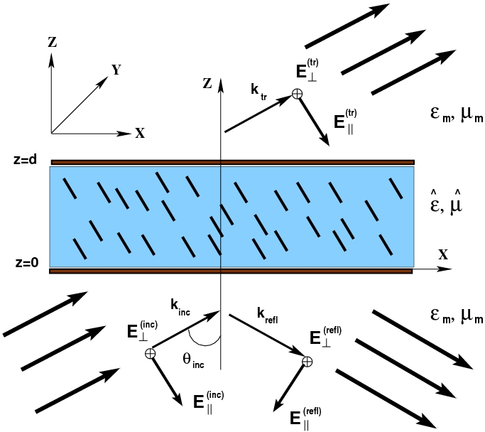
Figure 2: Geometry of nematic cell in the plane of incidence.

We shall need to write the Maxwell equations for a harmonic electromagnetic wave (time-dependent factor is exp{iωt}𝑖𝜔𝑡\exp\{-i\omega t\}) in the form:

×𝐄=iμkvac𝐇,bold-∇𝐄𝑖𝜇subscript𝑘vac𝐇\displaystyle\boldsymbol{\nabla}\times\mathbf{E}=i\mu k_{\mathrm{vac}}\mathbf{H}, (8a)
×𝐇=ikvac𝐃,bold-∇𝐇𝑖subscript𝑘vac𝐃\displaystyle\boldsymbol{\nabla}\times\mathbf{H}=-ik_{\mathrm{vac}}\mathbf{D}, (8b)

where kvac=ω/csubscript𝑘vac𝜔𝑐k_{\mathrm{vac}}=\omega/c is the free-space wave number; μ𝜇\mu is the magnetic permittivity and 𝐃=𝜺𝐄𝐃𝜺𝐄\mathbf{D}=\boldsymbol{\varepsilon}\cdot\mathbf{E} is the electric displacement field.

The medium surrounding the NLC cell is assumed to be optically isotropic and characterized by the dielectric constant ϵmsubscriptitalic-ϵm\epsilon_{\mathrm{m}} and the magnetic permittivity μmsubscript𝜇m\mu_{\mathrm{m}}. So, Maxwell’s equations in the medium outside the cell can be obtained from Eq. (8) by replacing μ𝜇\mu and 𝐃𝐃\mathbf{D} with μmsubscript𝜇m\mu_{\mathrm{m}} and ϵm𝐄subscriptitalic-ϵm𝐄\epsilon_{\mathrm{m}}\mathbf{E}, respectively.

As is shown in Fig. 2, there are two plane waves in the half space z0𝑧0z\leq 0 bounded by the entrance face of the NLC cell: the incoming incident wave {𝐄inc,𝐇inc}subscript𝐄incsubscript𝐇inc\{\mathbf{E}_{\mathrm{inc}},\mathbf{H}_{\mathrm{inc}}\} and the outgoing reflected wave {𝐄refl,𝐇refl}subscript𝐄reflsubscript𝐇refl\{\mathbf{E}_{\mathrm{refl}},\mathbf{H}_{\mathrm{refl}}\}. In the half space zd𝑧𝑑z\geq d after the exit face, the only wave is the transmitted plane wave {𝐄tr,𝐇tr}subscript𝐄trsubscript𝐇tr\{\mathbf{E}_{\mathrm{tr}},\mathbf{H}_{\mathrm{tr}}\} which propagates along the direction of incidence and is excited by the incident light.

So, the electric field outside the cell is a superposition of the plane wave solutions of the Maxwell equations

𝐄|z<0=𝐄inc(𝐤^inc)ei(𝐤inc𝐫)+𝐄refl(𝐤^refl)ei(𝐤refl𝐫),evaluated-at𝐄𝑧0subscript𝐄incsubscript^𝐤incsuperscripte𝑖subscript𝐤inc𝐫subscript𝐄reflsubscript^𝐤reflsuperscripte𝑖subscript𝐤refl𝐫\displaystyle\mathbf{E}|_{z<0}=\mathbf{E}_{\mathrm{inc}}(\hat{\mathbf{k}}_{\mathrm{inc}})\mathrm{e}^{i(\mathbf{k}_{\mathrm{inc}}\cdot\mathbf{r})}+\mathbf{E}_{\mathrm{refl}}(\hat{\mathbf{k}}_{\mathrm{refl}})\mathrm{e}^{i(\mathbf{k}_{\mathrm{refl}}\cdot\mathbf{r})}, (9a)
𝐄|z>d=𝐄tr(𝐤^tr)ei(𝐤tr𝐫),evaluated-at𝐄𝑧𝑑subscript𝐄trsubscript^𝐤trsuperscripte𝑖subscript𝐤tr𝐫\displaystyle\mathbf{E}|_{z>d}=\mathbf{E}_{\mathrm{tr}}(\hat{\mathbf{k}}_{\mathrm{tr}})\mathrm{e}^{i(\mathbf{k}_{\mathrm{tr}}\cdot\mathbf{r})}, (9b)

where the wave vectors 𝐤incsubscript𝐤inc\mathbf{k}_{\mathrm{inc}}, 𝐤reflsubscript𝐤refl\mathbf{k}_{\mathrm{refl}} and 𝐤trsubscript𝐤tr\mathbf{k}_{\mathrm{tr}} that are constrained to lie in the plane of incidence due to the boundary conditions requiring the tangential components of the electric and magnetic fields to be continuous at the boundary surfaces. These conditions are given by

𝐏(𝐳^)[𝐄|z=0+0𝐄|z=00]=𝐏(𝐳^)[𝐄|z=d+0𝐄|z=d0]=0,𝐏^𝐳delimited-[]evaluated-at𝐄𝑧00evaluated-at𝐄𝑧00𝐏^𝐳delimited-[]evaluated-at𝐄𝑧𝑑0evaluated-at𝐄𝑧𝑑00\displaystyle\mathbf{P}(\hat{\mathbf{z}})\cdot\bigl{[}\mathbf{E}|_{z=0+0}-\mathbf{E}|_{z=0-0}\bigr{]}=\mathbf{P}(\hat{\mathbf{z}})\cdot\bigl{[}\mathbf{E}|_{z=d+0}-\mathbf{E}|_{z=d-0}\bigr{]}=0, (10a)
𝐏(𝐳^)[𝐇|z=0+0𝐇|z=00]=𝐏(𝐳^)[𝐇|z=d+0𝐇|z=d0]=0,𝐏^𝐳delimited-[]evaluated-at𝐇𝑧00evaluated-at𝐇𝑧00𝐏^𝐳delimited-[]evaluated-at𝐇𝑧𝑑0evaluated-at𝐇𝑧𝑑00\displaystyle\mathbf{P}(\hat{\mathbf{z}})\cdot\bigl{[}\mathbf{H}|_{z=0+0}-\mathbf{H}|_{z=0-0}\bigr{]}=\mathbf{P}(\hat{\mathbf{z}})\cdot\bigl{[}\mathbf{H}|_{z=d+0}-\mathbf{H}|_{z=d-0}\bigr{]}=0, (10b)

where 𝐏(𝐳^)=𝐈3𝐳^𝐳^𝐏^𝐳subscript𝐈3tensor-product^𝐳^𝐳\mathbf{P}(\hat{\mathbf{z}})=\mathbf{I}_{3}-\hat{\mathbf{z}}\otimes\hat{\mathbf{z}} is the projector onto the plane with the normal directed along the vector 𝐳^^𝐳\hat{\mathbf{z}} (the x𝑥x-y𝑦y plane).

Another consequence of the boundary conditions (10) is that the tangential components of the wave vectors are the same. Assuming that the incidence plane is the x𝑥x-z𝑧z plane we have

𝐤α=kvac𝐪α=km𝐤^α=kx𝐱^+kz(α)𝐳^,α{inc,refl,tr},formulae-sequencesubscript𝐤𝛼subscript𝑘vacsubscript𝐪𝛼subscript𝑘msubscript^𝐤𝛼subscript𝑘𝑥^𝐱superscriptsubscript𝑘𝑧𝛼^𝐳𝛼increfltr\displaystyle\mathbf{k}_{\alpha}=k_{\mathrm{vac}}\mathbf{q}_{\alpha}=k_{\mathrm{m}}\hat{\mathbf{k}}_{\alpha}=k_{x}\,\hat{\mathbf{x}}+k_{z}^{(\alpha)}\,\hat{\mathbf{z}},\quad\alpha\in\{\mathrm{inc},\mathrm{refl},\mathrm{tr}\}, (11)

where km/kvac=nm=μmϵmsubscript𝑘msubscript𝑘vacsubscript𝑛msubscript𝜇msubscriptitalic-ϵmk_{\mathrm{m}}/k_{\mathrm{vac}}=n_{\mathrm{m}}=\sqrt{\mu_{\mathrm{m}}\epsilon_{\mathrm{m}}} is the refractive index of the ambient medium and the components can be expressed in terms of the incidence angle θincsubscript𝜃inc\theta_{\mathrm{inc}} as follows

kx=kmsinθinckvacqx,subscript𝑘𝑥subscript𝑘msubscript𝜃incsubscript𝑘vacsubscript𝑞𝑥\displaystyle k_{x}=k_{\mathrm{m}}\sin\theta_{\mathrm{inc}}\equiv k_{\mathrm{vac}}\,q_{x}, (12)
kz(inc)=kz(tr)=kz(refl)=kmcosθinckvacqz(m).superscriptsubscript𝑘𝑧incsuperscriptsubscript𝑘𝑧trsuperscriptsubscript𝑘𝑧reflsubscript𝑘msubscript𝜃incsubscript𝑘vacsuperscriptsubscript𝑞𝑧m\displaystyle k_{z}^{(\mathrm{inc})}=k_{z}^{(\mathrm{tr})}=-k_{z}^{(\mathrm{refl})}=k_{\mathrm{m}}\cos\theta_{\mathrm{inc}}\equiv k_{\mathrm{vac}}\,q_{z}^{(\mathrm{m})}. (13)

The plane wave traveling in the isotropic ambient medium along the wave vector (11) is transverse, so that the polarization vector is given by

𝐄α(𝐤^α)=E(α)𝐞1(𝐤^α)+E(α)𝐞2(𝐤^α),subscript𝐄𝛼subscript^𝐤𝛼superscriptsubscript𝐸parallel-to𝛼subscript𝐞1subscript^𝐤𝛼superscriptsubscript𝐸perpendicular-to𝛼subscript𝐞2subscript^𝐤𝛼\displaystyle\mathbf{E}_{\alpha}(\hat{\mathbf{k}}_{\alpha})=E_{\parallel}^{(\alpha)}\mathbf{e}_{1}(\hat{\mathbf{k}}_{\alpha})+E_{\perp}^{(\alpha)}\mathbf{e}_{2}(\hat{\mathbf{k}}_{\alpha}), (14)
𝐞1(𝐤^α)=km1(kz(α)𝐱^kx𝐳^),𝐞2(𝐤^α)=𝐲^,formulae-sequencesubscript𝐞1subscript^𝐤𝛼superscriptsubscript𝑘m1superscriptsubscript𝑘𝑧𝛼^𝐱subscript𝑘𝑥^𝐳subscript𝐞2subscript^𝐤𝛼^𝐲\displaystyle\mathbf{e}_{1}(\hat{\mathbf{k}}_{\alpha})=k_{\mathrm{m}}^{-1}\bigl{(}k_{z}^{(\alpha)}\,\hat{\mathbf{x}}-k_{x}\,\hat{\mathbf{z}}\bigr{)},\quad\mathbf{e}_{2}(\hat{\mathbf{k}}_{\alpha})=\hat{\mathbf{y}}, (15)

where E(α)superscriptsubscript𝐸parallel-to𝛼E_{\parallel}^{(\alpha)} and E(α)superscriptsubscript𝐸perpendicular-to𝛼E_{\perp}^{(\alpha)} are the in-plane and out-of-plane components of the electric field, respectively. The vector characterizing the magnetic field is

μm𝐇α(𝐤^α)=𝐪α×𝐄α(𝐤^α)=nm[E(α)𝐲^E(α)𝐞1(𝐤^α)],subscript𝜇msubscript𝐇𝛼subscript^𝐤𝛼subscript𝐪𝛼subscript𝐄𝛼subscript^𝐤𝛼subscript𝑛mdelimited-[]superscriptsubscript𝐸parallel-to𝛼^𝐲superscriptsubscript𝐸perpendicular-to𝛼subscript𝐞1subscript^𝐤𝛼\displaystyle\mu_{\mathrm{m}}\,\mathbf{H}_{\alpha}(\hat{\mathbf{k}}_{\alpha})=\mathbf{q}_{\alpha}\times\mathbf{E}_{\alpha}(\hat{\mathbf{k}}_{\alpha})=n_{\mathrm{m}}\,\bigl{[}E_{\parallel}^{(\alpha)}\hat{\mathbf{y}}-E_{\perp}^{(\alpha)}\mathbf{e}_{1}(\hat{\mathbf{k}}_{\alpha})\bigr{]}, (16)

where 𝐪α=kvac1𝐤α=nm𝐤^αsubscript𝐪𝛼superscriptsubscript𝑘vac1subscript𝐤𝛼subscript𝑛msubscript^𝐤𝛼\mathbf{q}_{\alpha}=k_{\mathrm{vac}}^{-1}\mathbf{k}_{\alpha}=n_{\mathrm{m}}\hat{\mathbf{k}}_{\alpha}. Note that, for plane waves, the dimensionless vector

𝐪=kvac1𝐤𝐪superscriptsubscript𝑘vac1𝐤\mathbf{q}=k_{\mathrm{vac}}^{-1}\mathbf{k} (17)

is parallel to 𝐤𝐤\mathbf{k} and its length gives the refractive index. For convenience, we shall often use this vector in place of the wave vector.

The expressions (9)–(16) give the electromagnetic field of incident, transmitted and reflected waves propagating in the ambient medium. This field is of the general form

{𝐄(𝐫),𝐇(𝐫)}={𝐄(z),𝐇(z)}exp[i(𝐤P,𝐫)],𝐤P=𝐏(𝐳^)𝐤,formulae-sequence𝐄𝐫𝐇𝐫𝐄𝑧𝐇𝑧𝑖subscript𝐤𝑃𝐫subscript𝐤𝑃𝐏^𝐳𝐤\displaystyle\left\{\mathbf{E}(\mathbf{r}),\mathbf{H}(\mathbf{r})\right\}=\left\{\mathbf{E}(z),\mathbf{H}(z)\right\}\exp[i\bigl{(}{\mathbf{k}_{P}},{\mathbf{r}}\bigr{)}],\quad\mathbf{k}_{P}=\mathbf{P}(\hat{\mathbf{z}})\cdot\mathbf{k}, (18)
𝐪P=kvac1𝐤P=qP[cos(ϕinc)𝐱^+sin(ϕinc)𝐲^],subscript𝐪𝑃superscriptsubscript𝑘vac1subscript𝐤𝑃subscript𝑞𝑃delimited-[]subscriptitalic-ϕinc^𝐱subscriptitalic-ϕinc^𝐲\displaystyle\mathbf{q}_{P}=k_{\mathrm{vac}}^{-1}\,\mathbf{k}_{P}=q_{P}\left[\cos(\phi_{\mathrm{inc}})\,\hat{\mathbf{x}}+\sin(\phi_{\mathrm{inc}})\,\hat{\mathbf{y}}\right], (19)

where the azimuthal angle ϕincsubscriptitalic-ϕinc\phi_{\mathrm{inc}} specifies orientation of the incidence plane. So, in our case, we have ϕinc=0subscriptitalic-ϕinc0\phi_{\mathrm{inc}}=0 and qP=qxsubscript𝑞𝑃subscript𝑞𝑥q_{P}=q_{x}.

The representation (18) can be applied to describe the field inside the cell when the dielectric tensor is independent of the in-plane coordinates x𝑥x and y𝑦y. In this case the lateral components of the electric and magnetic fields

𝐄P=𝐏(𝐳^)𝐄=Ex𝐱^+Ey𝐲^(ExEy),subscript𝐄𝑃𝐏^𝐳𝐄subscript𝐸𝑥^𝐱subscript𝐸𝑦^𝐲matrixsubscript𝐸𝑥subscript𝐸𝑦\displaystyle\mathbf{E}_{P}=\mathbf{P}(\hat{\mathbf{z}})\cdot\mathbf{E}=E_{x}\hat{\mathbf{x}}+E_{y}\hat{\mathbf{y}}\equiv\begin{pmatrix}E_{x}\\ E_{y}\end{pmatrix}, (20)
𝐇P=𝐇×𝐳^=Hy𝐱^Hx𝐲^(HyHx)subscript𝐇𝑃𝐇^𝐳subscript𝐻𝑦^𝐱subscript𝐻𝑥^𝐲matrixsubscript𝐻𝑦subscript𝐻𝑥\displaystyle\mathbf{H}_{P}=\mathbf{H}\times\hat{\mathbf{z}}=H_{y}\hat{\mathbf{x}}-H_{x}\hat{\mathbf{y}}\equiv\begin{pmatrix}H_{y}\\ -H_{x}\end{pmatrix} (21)

can be conveniently combined into the vector

𝐅(z)(𝐄P(z)𝐇P(z))=(Ex(z)Ey(z)Hy(z)Hx(z)).𝐅𝑧matrixsubscript𝐄𝑃𝑧subscript𝐇𝑃𝑧matrixsubscript𝐸𝑥𝑧subscript𝐸𝑦𝑧subscript𝐻𝑦𝑧subscript𝐻𝑥𝑧\displaystyle\mathbf{F}(z)\equiv\begin{pmatrix}\mathbf{E}_{P}(z)\\ \mathbf{H}_{P}(z)\end{pmatrix}=\begin{pmatrix}E_{x}(z)\\ E_{y}(z)\\ H_{y}(z)\\ -H_{x}(z)\end{pmatrix}. (22)

From Maxwell’s equations (8), the components normal to the substrates, Ezsubscript𝐸𝑧E_{z} and Hzsubscript𝐻𝑧H_{z}, can be readily expressed in terms of the lateral components

μHz=(𝐪P,𝐄P×𝐳^),ϵzzEz=(𝐳^,𝜺𝐄P)(𝐪P,𝐇P).formulae-sequence𝜇subscript𝐻𝑧subscript𝐪𝑃subscript𝐄𝑃^𝐳subscriptitalic-ϵ𝑧𝑧subscript𝐸𝑧^𝐳𝜺subscript𝐄𝑃subscript𝐪𝑃subscript𝐇𝑃\displaystyle\mu H_{z}=\bigl{(}{\mathbf{q}_{P}},{\mathbf{E}_{P}\times\hat{\mathbf{z}}}\bigr{)},\quad\epsilon_{zz}E_{z}=-\bigl{(}{\hat{\mathbf{z}}},{\boldsymbol{\varepsilon}\cdot\mathbf{E}_{P}}\bigr{)}-\bigl{(}{\mathbf{q}_{P}},{\mathbf{H}_{P}}\bigr{)}. (23)

By using the relations (23) to eliminate the normal components we obtain the equation for the field vector (22) in the following matrix form

iτ𝐅=𝐌𝐅(𝐌11𝐌12𝐌21𝐌22)(𝐄P𝐇P),τkvacz,formulae-sequence𝑖subscript𝜏𝐅𝐌𝐅matrixsubscript𝐌11subscript𝐌12subscript𝐌21subscript𝐌22matrixsubscript𝐄𝑃subscript𝐇𝑃𝜏subscript𝑘vac𝑧\displaystyle-i\partial_{\tau}\mathbf{F}=\mathbf{M}\cdot\mathbf{F}\equiv\begin{pmatrix}\mathbf{M}_{11}&\mathbf{M}_{12}\\ \mathbf{M}_{21}&\mathbf{M}_{22}\end{pmatrix}\begin{pmatrix}\mathbf{E}_{P}\\ \mathbf{H}_{P}\end{pmatrix},\quad\tau\equiv k_{\mathrm{vac}}z, (24)

where

Mαβ(11)=ϵzz1qα(P)ϵzβ,subscriptsuperscript𝑀11𝛼𝛽superscriptsubscriptitalic-ϵ𝑧𝑧1subscriptsuperscript𝑞𝑃𝛼subscriptitalic-ϵ𝑧𝛽\displaystyle M^{(11)}_{\alpha\beta}=-\epsilon_{zz}^{-1}q^{(P)}_{\alpha}\epsilon_{z\beta}, (25a)
Mαβ(22)=ϵzz1ϵαzqβ(P),subscriptsuperscript𝑀22𝛼𝛽superscriptsubscriptitalic-ϵ𝑧𝑧1subscriptitalic-ϵ𝛼𝑧subscriptsuperscript𝑞𝑃𝛽\displaystyle M^{(22)}_{\alpha\beta}=-\epsilon_{zz}^{-1}\epsilon_{\alpha z}q^{(P)}_{\beta}, (25b)
Mαβ(12)=μδαβϵzz1qα(P)qβ(P),subscriptsuperscript𝑀12𝛼𝛽𝜇subscript𝛿𝛼𝛽superscriptsubscriptitalic-ϵ𝑧𝑧1subscriptsuperscript𝑞𝑃𝛼subscriptsuperscript𝑞𝑃𝛽\displaystyle M^{(12)}_{\alpha\beta}=\mu\delta_{\alpha\beta}-\epsilon_{zz}^{-1}q^{(P)}_{\alpha}q^{(P)}_{\beta}, (25c)
Mαβ(21)=ϵαβμ1pα(P)pβ(P)ϵzz1ϵαzϵzβ,subscriptsuperscript𝑀21𝛼𝛽subscriptitalic-ϵ𝛼𝛽superscript𝜇1subscriptsuperscript𝑝𝑃𝛼subscriptsuperscript𝑝𝑃𝛽superscriptsubscriptitalic-ϵ𝑧𝑧1subscriptitalic-ϵ𝛼𝑧subscriptitalic-ϵ𝑧𝛽\displaystyle M^{(21)}_{\alpha\beta}=\epsilon_{\alpha\beta}-\mu^{-1}p^{(P)}_{\alpha}p^{(P)}_{\beta}-\epsilon_{zz}^{-1}\epsilon_{\alpha z}\epsilon_{z\beta}, (25d)

where δαβsubscript𝛿𝛼𝛽\delta_{\alpha\beta} is the Kroneker symbol, 𝐪P=kvac1𝐤Psubscript𝐪𝑃superscriptsubscript𝑘vac1subscript𝐤𝑃\mathbf{q}_{P}=k_{\mathrm{vac}}^{-1}\,\mathbf{k}_{P} and 𝐩P=𝐳^×𝐪Psubscript𝐩𝑃^𝐳subscript𝐪𝑃\mathbf{p}_{P}=\hat{\mathbf{z}}\times\mathbf{q}_{P}.

The field vector (22) can now be written in the form of a general solution to the linear problem (24)

𝐅(τ)=𝐔(τ)𝐅(0),𝐅𝜏𝐔𝜏𝐅0\displaystyle\mathbf{F}(\tau)=\mathbf{U}(\tau)\cdot\mathbf{F}(0), (26)

where 𝐔(τ)𝐔𝜏\mathbf{U}(\tau) is the evolution operator that can be determined by solving the initial value problem

iτ𝐔=𝐌𝐔,𝐔(0)=𝐈4.formulae-sequence𝑖subscript𝜏𝐔𝐌𝐔𝐔0subscript𝐈4\displaystyle-i\partial_{\tau}\mathbf{U}=\mathbf{M}\cdot\mathbf{U},\quad\mathbf{U}(0)=\mathbf{I}_{4}. (27)

Our above notations can be regarded as a version of the well known matrix formalism due to Berreman Berreman (1972). By using these notations we derive the boundary conditions (10) in the matrix form

𝐅<=𝐕m(𝐄inc𝐄refl)=𝐅(0),subscript𝐅subscript𝐕mmatrixsubscript𝐄incsubscript𝐄refl𝐅0\displaystyle\mathbf{F}_{<}=\mathbf{V}_{\mathrm{m}}\begin{pmatrix}\mathbf{E}_{\mathrm{inc}}\\ \mathbf{E}_{\mathrm{refl}}\end{pmatrix}=\mathbf{F}(0), (28a)
𝐅>=𝐕m(𝐄tr𝟎)=𝐅(h),hkvacd,formulae-sequencesubscript𝐅subscript𝐕mmatrixsubscript𝐄tr0𝐅subscript𝑘vac𝑑\displaystyle\mathbf{F}_{>}=\mathbf{V}_{\mathrm{m}}\begin{pmatrix}\mathbf{E}_{\mathrm{tr}}\\ \mathbf{0}\end{pmatrix}=\mathbf{F}(h),\quad h\equiv k_{\mathrm{vac}}\,d, (28b)

where 𝐄α(E(α)E(α))subscript𝐄𝛼matrixsuperscriptsubscript𝐸parallel-to𝛼superscriptsubscript𝐸perpendicular-to𝛼\mathbf{E}_{\alpha}\equiv\begin{pmatrix}E_{\parallel}^{(\alpha)}\\ E_{\perp}^{(\alpha)}\end{pmatrix}.

The matrix 𝐕msubscript𝐕m\mathbf{V}_{\mathrm{m}} relates the field vectors, 𝐅<𝐅(00)subscript𝐅𝐅00\mathbf{F}_{<}\equiv\mathbf{F}(0-0) and 𝐅>𝐅(h+0)subscript𝐅𝐅0\mathbf{F}_{>}\equiv\mathbf{F}(h+0), and the vector amplitudes 𝐄αsubscript𝐄𝛼\mathbf{E}_{\alpha} of the waves in the surrounding medium. From Eqs. (14)-(16), its block structure

𝐕m=(𝐄m𝝈3𝐄m𝐇m𝝈3𝐇m)subscript𝐕mmatrixsubscript𝐄msubscript𝝈3subscript𝐄msubscript𝐇msubscript𝝈3subscript𝐇m\displaystyle\mathbf{V}_{\mathrm{m}}=\begin{pmatrix}\mathbf{E}_{\mathrm{m}}&-\boldsymbol{\sigma}_{3}\mathbf{E}_{\mathrm{m}}\\ \mathbf{H}_{\mathrm{m}}&\boldsymbol{\sigma}_{3}\mathbf{H}_{\mathrm{m}}\\ \end{pmatrix} (29)

is characterized by the two diagonal 2×2222\times 2 matrices

𝐄m=diag(qz(m)/nm,1),μm𝐇m=diag(nm,qz(m)),formulae-sequencesubscript𝐄mdiagsuperscriptsubscript𝑞𝑧msubscript𝑛m1subscript𝜇msubscript𝐇mdiagsubscript𝑛msuperscriptsubscript𝑞𝑧m\displaystyle\mathbf{E}_{\mathrm{m}}=\mathop{\rm diag}\nolimits(q_{z}^{(\mathrm{m})}/n_{\mathrm{m}},1),\quad\mu_{\mathrm{m}}\,\mathbf{H}_{\mathrm{m}}=\mathop{\rm diag}\nolimits(n_{\mathrm{m}},q_{z}^{(\mathrm{m})}), (30)

where qz(m)=nm2qx2superscriptsubscript𝑞𝑧msuperscriptsubscript𝑛m2superscriptsubscript𝑞𝑥2q_{z}^{(\mathrm{m})}=\sqrt{n_{\mathrm{m}}^{2}-q_{x}^{2}} and 𝝈3=diag(1,1)subscript𝝈3diag11\boldsymbol{\sigma}_{3}=\mathop{\rm diag}\nolimits(1,-1).

It is rather starightforward to check the validity of the algebraic identity for the matrix (29)

[𝐕m]T𝐆𝐕m=𝐍m=Nmdiag(𝐈2,𝐈2),𝐆(𝟎𝐈2𝐈2𝟎),formulae-sequencesuperscriptdelimited-[]subscript𝐕m𝑇𝐆subscript𝐕msubscript𝐍msubscript𝑁mdiagsubscript𝐈2subscript𝐈2𝐆matrix0subscript𝐈2subscript𝐈20\displaystyle{[\mathbf{V}_{\mathrm{m}}]}^{T}\cdot\mathbf{G}\cdot\mathbf{V}_{\mathrm{m}}=\mathbf{N}_{\mathrm{m}}=N_{\mathrm{m}}\mathop{\rm diag}\nolimits(\mathbf{I}_{2},-\mathbf{I}_{2}),\quad\mathbf{G}\equiv\begin{pmatrix}\mathbf{0}&\mathbf{I}_{2}\\ \mathbf{I}_{2}&\mathbf{0}\end{pmatrix}, (31)

where Nm=2qz(m)/μmsubscript𝑁m2superscriptsubscript𝑞𝑧msubscript𝜇mN_{\mathrm{m}}=2q_{z}^{(\mathrm{m})}/\mu_{\mathrm{m}} and the superscript T𝑇T indicates matrix transposition.

According to Ref. Oldano (1989), identities of the form (31) can be derived as the orthogonality relations resulted from the conservation law for the energy flux in non-absorbing media. Algebraically, Eq. (31) can be used to simplify inversion of the matrix 𝐕msubscript𝐕m\mathbf{V}_{\mathrm{m}}

𝐕m1=𝐍m1[𝐕m]T𝐆superscriptsubscript𝐕m1superscriptsubscript𝐍m1superscriptdelimited-[]subscript𝐕m𝑇𝐆\displaystyle\mathbf{V}_{\mathrm{m}}^{-1}=\mathbf{N}_{\mathrm{m}}^{-1}\cdot{[\mathbf{V}_{\mathrm{m}}]}^{T}\cdot\mathbf{G} (32)

and to ease qualitative analysis [see , e.g., Ref. Yakovlev (1998) for a more extended discussion of applications].

After substituting Eq. (26) into the boundary conditions (28a) we have

(𝐄inc𝐄refl)=𝐖(𝐄tr𝟎),matrixsubscript𝐄incsubscript𝐄refl𝐖matrixsubscript𝐄tr0\displaystyle\begin{pmatrix}\mathbf{E}_{\mathrm{inc}}\\ \mathbf{E}_{\mathrm{refl}}\end{pmatrix}=\mathbf{W}\begin{pmatrix}\mathbf{E}_{\mathrm{tr}}\\ \mathbf{0}\end{pmatrix}, (33)
𝐖=𝐕m1𝐔1(h)𝐕m=(𝐖11𝐖12𝐖21𝐕22),𝐖superscriptsubscript𝐕m1superscript𝐔1subscript𝐕mmatrixsubscript𝐖11subscript𝐖12subscript𝐖21subscript𝐕22\displaystyle\mathbf{W}=\mathbf{V}_{\mathrm{m}}^{-1}\cdot\mathbf{U}^{-1}(h)\cdot\mathbf{V}_{\mathrm{m}}=\begin{pmatrix}\mathbf{W}_{11}&\mathbf{W}_{12}\\ \mathbf{W}_{21}&\mathbf{V}_{22}\end{pmatrix}, (34)

where 𝐔1𝐔1(h)superscript𝐔1superscript𝐔1\mathbf{U}^{-1}\equiv\mathbf{U}^{-1}(h).

From Eq. (33) we have

(E(tr)E(tr))matrixsuperscriptsubscript𝐸parallel-totrsuperscriptsubscript𝐸perpendicular-totr\displaystyle\begin{pmatrix}E_{\parallel}^{(\mathrm{tr})}\\ E_{\perp}^{(\mathrm{tr})}\end{pmatrix} =𝐓(E(inc)E(inc)),absent𝐓matrixsuperscriptsubscript𝐸parallel-toincsuperscriptsubscript𝐸perpendicular-toinc\displaystyle=\mathbf{T}\begin{pmatrix}E_{\parallel}^{(\mathrm{inc})}\\ E_{\perp}^{(\mathrm{inc})}\end{pmatrix}, (35)
𝐓𝐓\displaystyle\mathbf{T} =𝐖111,absentsuperscriptsubscript𝐖111\displaystyle=\mathbf{W}_{11}^{-1}, (36)

where 𝐓𝐓\mathbf{T} is the transmission (transfer) matrix linking the transmitted and incident waves.

Similar result for the reflected wave is

(E(refl)E(refl))=𝐑(E(inc)E(inc)),matrixsuperscriptsubscript𝐸parallel-toreflsuperscriptsubscript𝐸perpendicular-torefl𝐑matrixsuperscriptsubscript𝐸parallel-toincsuperscriptsubscript𝐸perpendicular-toinc\displaystyle\begin{pmatrix}E_{\parallel}^{(\mathrm{refl})}\\ E_{\perp}^{(\mathrm{refl})}\end{pmatrix}=\mathbf{R}\begin{pmatrix}E_{\parallel}^{(\mathrm{inc})}\\ E_{\perp}^{(\mathrm{inc})}\end{pmatrix}, (37)
𝐑=𝐖21𝐖111=𝐖21𝐓,𝐑subscript𝐖21superscriptsubscript𝐖111subscript𝐖21𝐓\displaystyle\mathbf{R}=\mathbf{W}_{21}\cdot\mathbf{W}_{11}^{-1}=\mathbf{W}_{21}\cdot\mathbf{T}, (38)

where 𝐑𝐑\mathbf{R} is the reflection matrix.

For uniformly anisotropic media, the elements of the matrix (25) are constants and solving Eq. (27) gives the formula for the evolution matrix

𝐔(τ)=exp{i𝐌τ}=𝐕exp{i𝚲τ}𝐕1,𝐔𝜏𝑖𝐌𝜏𝐕𝑖𝚲𝜏superscript𝐕1\displaystyle\mathbf{U}(\tau)=\exp\{i\mathbf{M}\tau\}=\mathbf{V}\cdot\exp\{i\boldsymbol{\Lambda}\tau\}\cdot\mathbf{V}^{-1}, (39)
𝚲=diag(λ1,λ2,λ3,λ4),𝐌𝐕=𝐕𝚲,formulae-sequence𝚲diagsubscript𝜆1subscript𝜆2subscript𝜆3subscript𝜆4𝐌𝐕𝐕𝚲\displaystyle\boldsymbol{\Lambda}=\mathop{\rm diag}\nolimits(\lambda_{1},\lambda_{2},\lambda_{3},\lambda_{4}),\quad\mathbf{M}\cdot\mathbf{V}=\mathbf{V}\cdot\boldsymbol{\Lambda}, (40)

where λisubscript𝜆𝑖\lambda_{i} is the eigenvalue of the matrix 𝐌𝐌\mathbf{M} and 𝐕=(𝐕1𝐕2𝐕3𝐕4)𝐕subscript𝐕1subscript𝐕2subscript𝐕3subscript𝐕4\mathbf{V}=(\mathbf{V}_{1}\,\mathbf{V}_{2}\,\mathbf{V}_{3}\,\mathbf{V}_{4}) is the matrix composed of the right eigenvectors, 𝐌𝐕i=λi𝐕i𝐌subscript𝐕𝑖subscript𝜆𝑖subscript𝐕𝑖\mathbf{M}\cdot\mathbf{V}_{i}=\lambda_{i}\,\mathbf{V}_{i}. Technical details on computing the evolution operator for both biaxial and uniaxial anisotropies can be found in Appendix A. In this section we restrict ourselves to the simplest (and important for our purposes) case that occurs when the NLC cell is homeotropically aligned.

For the homeotropic director structure with 𝐝^=𝐳^^𝐝^𝐳\hat{\mathbf{d}}=\hat{\mathbf{z}}, the eigenvalue problem for the matrix 𝐌𝐌\mathbf{M} is easy to solve. The result is

𝚲=diag(qz(e),qz(o),qz(e),qz(o)),𝐕=(𝐄+𝝈3𝐄+𝐇+𝝈3𝐇+),formulae-sequence𝚲diagsuperscriptsubscript𝑞𝑧𝑒superscriptsubscript𝑞𝑧𝑜superscriptsubscript𝑞𝑧𝑒superscriptsubscript𝑞𝑧𝑜𝐕matrixsubscript𝐄subscript𝝈3subscript𝐄subscript𝐇subscript𝝈3subscript𝐇\displaystyle\boldsymbol{\Lambda}=\mathop{\rm diag}\nolimits(q_{z}^{(e)},q_{z}^{(o)},-q_{z}^{(e)},-q_{z}^{(o)}),\quad\mathbf{V}=\begin{pmatrix}\mathbf{E}_{+}&-\boldsymbol{\sigma}_{3}\mathbf{E}_{+}\\ \mathbf{H}_{+}&\boldsymbol{\sigma}_{3}\mathbf{H}_{+}\\ \end{pmatrix}, (41)
𝐄+=diag(qz(e)/n,1),μ𝐇+=diag(n,qz(o)),formulae-sequencesubscript𝐄diagsuperscriptsubscript𝑞𝑧𝑒subscript𝑛perpendicular-to1𝜇subscript𝐇diagsubscript𝑛perpendicular-tosuperscriptsubscript𝑞𝑧𝑜\displaystyle\mathbf{E}_{+}=\mathop{\rm diag}\nolimits(q_{z}^{(e)}/n_{\perp},1),\quad\mu\mathbf{H}_{+}=\mathop{\rm diag}\nolimits(n_{\perp},q_{z}^{(o)}), (42)

where qz(o)=n2qx2superscriptsubscript𝑞𝑧𝑜superscriptsubscript𝑛perpendicular-to2superscriptsubscript𝑞𝑥2q_{z}^{(o)}=\sqrt{n_{\perp}^{2}-q_{x}^{2}} and qz(e)=nn1n2qx2superscriptsubscript𝑞𝑧𝑒subscript𝑛perpendicular-tosuperscriptsubscript𝑛parallel-to1superscriptsubscript𝑛parallel-to2superscriptsubscript𝑞𝑥2q_{z}^{(e)}=n_{\perp}n_{\parallel}^{-1}\sqrt{n_{\parallel}^{2}-q_{x}^{2}}.

The analytical relations (41) can now be substituted into the expression (39) to yield the evolution matrix 𝐔1(h)=𝐔(h)superscript𝐔1𝐔\mathbf{U}^{-1}(h)=\mathbf{U}(-h) that enter the linking matrix 𝐖𝐖\mathbf{W} defined in Eq. (34). The final step involves substituting the block 2×2222\times 2 matrices 𝐖11subscript𝐖11\mathbf{W}_{11} and 𝐖21subscript𝐖21\mathbf{W}_{21} into Eqs. (36) and (38) to find the transfer and the transmission matrices in the following form

𝐓=diag(te,to)=[cos(𝚲+h)i𝚪+sin(𝚲+h)]1,𝐓diagsubscript𝑡𝑒subscript𝑡𝑜superscriptdelimited-[]subscript𝚲𝑖subscript𝚪subscript𝚲1\displaystyle\mathbf{T}=\mathop{\rm diag}\nolimits(t_{e},t_{o})=\Bigl{[}\cos(\boldsymbol{\Lambda}_{+}h)-i\boldsymbol{\Gamma}_{+}\cdot\sin(\boldsymbol{\Lambda}_{+}h)\Bigr{]}^{-1}, (43)
𝐑=diag(re,ro)=i𝝈3𝚪sin(𝚲+h)𝐓,𝐑diagsubscript𝑟𝑒subscript𝑟𝑜𝑖subscript𝝈3subscript𝚪subscript𝚲𝐓\displaystyle\mathbf{R}=\mathop{\rm diag}\nolimits(r_{e},r_{o})=-i\boldsymbol{\sigma}_{3}\cdot\boldsymbol{\Gamma}_{-}\cdot\sin(\boldsymbol{\Lambda}_{+}h)\cdot\mathbf{T}, (44)

where

𝚲+h=diag(qz(e),qz(o))hdiag(δe,δo),subscript𝚲diagsuperscriptsubscript𝑞𝑧𝑒superscriptsubscript𝑞𝑧𝑜diagsubscript𝛿𝑒subscript𝛿𝑜\displaystyle\boldsymbol{\Lambda}_{+}h=\mathop{\rm diag}\nolimits(q_{z}^{(e)},q_{z}^{(o)})h\equiv\mathop{\rm diag}\nolimits(\delta_{e},\delta_{o}), (45)
𝚪±=(𝚪±𝚪1)/2,𝚪=μmμ(no2qz(m)nm2qz(e)00qz(o)qz(m))diag(γe,γo).formulae-sequencesubscript𝚪plus-or-minusplus-or-minus𝚪superscript𝚪12𝚪subscript𝜇m𝜇matrixsuperscriptsubscript𝑛𝑜2superscriptsubscript𝑞𝑧msuperscriptsubscript𝑛m2superscriptsubscript𝑞𝑧𝑒00superscriptsubscript𝑞𝑧𝑜superscriptsubscript𝑞𝑧mdiagsubscript𝛾𝑒subscript𝛾𝑜\displaystyle\boldsymbol{\Gamma}_{\pm}=(\boldsymbol{\Gamma}\pm\boldsymbol{\Gamma}^{-1})/2,\quad\boldsymbol{\Gamma}=\frac{\mu_{\mathrm{m}}}{\mu}\begin{pmatrix}\dfrac{n_{o}^{2}q_{z}^{(\mathrm{m})}}{n_{\mathrm{m}}^{2}q_{z}^{(e)}}&0\\ 0&\dfrac{q_{z}^{(o)}}{q_{z}^{(\mathrm{m})}}\end{pmatrix}\equiv\mathop{\rm diag}\nolimits(\gamma_{e},\gamma_{o}). (46)
Refer to caption
(a) Star: IC=1/2subscript𝐼𝐶12I_{C}=-1/2 and NC=3subscript𝑁𝐶3N_{C}=3
Refer to caption
(b) Lemon: IC=+1/2subscript𝐼𝐶12I_{C}=+1/2 and NC=1subscript𝑁𝐶1N_{C}=1
Refer to caption
(c) Monstar: IC=+1/2subscript𝐼𝐶12I_{C}=+1/2 and NC=3subscript𝑁𝐶3N_{C}=3
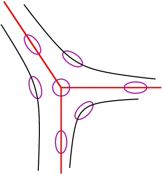
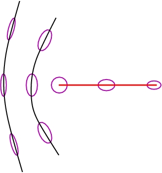
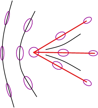
Figure 3: Arrangment of the polarization ellipses around the C-points of three different types.

III.2 Polarization resolved angular patterns

We will now proceed to a study of how the polarization properties of the transmitted wave depend on the direction of the incident beam. This direction is specified by two angles: the incidence angle θincsubscript𝜃inc\theta_{\mathrm{inc}} and the azimuthal angle of the plane of incidence ϕincsubscriptitalic-ϕinc\phi_{\mathrm{inc}}.

In the previous section and in Appendix A, the transmission problem was analyzed in the plane of incidence where ϕinc=0subscriptitalic-ϕinc0\phi_{\mathrm{inc}}=0. Clearly, when ϕinc0subscriptitalic-ϕinc0\phi_{\mathrm{inc}}\neq 0, in order to have the Euler angles describing orientation of the director (4) with respect to the incidence plane we need to replace the director azimuthal angle ϕdsubscriptitalic-ϕd\phi_{\mathrm{d}} with ϕdϕincsubscriptitalic-ϕdsubscriptitalic-ϕinc\phi_{\mathrm{d}}-\phi_{\mathrm{inc}}.

In this section dependence of the polarization parameters of transmitted waves on the angles θincsubscript𝜃inc\theta_{\mathrm{inc}} and ϕincsubscriptitalic-ϕinc\phi_{\mathrm{inc}} will be of our primary concern. For this purpose, we assume that the transmission matrix 𝐓(θinc,θd,ϕd)𝐓subscript𝜃incsubscript𝜃dsubscriptitalic-ϕd\mathbf{T}(\theta_{\mathrm{inc}},\theta_{\mathrm{d}},\phi_{\mathrm{d}}) considered in Sec. III.1 and in Appendix A is changed to 𝐓(θinc,θd,ϕdϕinc)𝐓subscript𝜃incsubscript𝜃dsubscriptitalic-ϕdsubscriptitalic-ϕinc\mathbf{T}(\theta_{\mathrm{inc}},\theta_{\mathrm{d}},\phi_{\mathrm{d}}-\phi_{\mathrm{inc}}).

As previously discussed in Sec. II, experimentally, the characteristics of the polarization ellipse can be determined by measuring the Stokes parameters (1). These parameters are related to the coherence matrix with the elements 𝐌αβ=EαEβsubscript𝐌𝛼𝛽subscript𝐸𝛼superscriptsubscript𝐸𝛽\mathbf{M}_{\alpha\beta}=E_{\alpha}{E_{\beta}}^{\ast}, where α,β{,}\alpha,\beta\in\{\parallel,\perp\} Born and Wolf (1999); Azzam and Bashara (1977). In the circular basis, 2𝐞±(𝐤^)=𝐞1(𝐤^)±i𝐞2(𝐤^)2subscript𝐞plus-or-minus^𝐤plus-or-minussubscript𝐞1^𝐤𝑖subscript𝐞2^𝐤\sqrt{2}\,\mathbf{e}_{\pm}(\hat{\mathbf{k}})=\mathbf{e}_{1}(\hat{\mathbf{k}})\pm i\mathbf{e}_{2}(\hat{\mathbf{k}}), this matrix written as a linear combination of the Pauli matrices gives the Stokes parameters, Sisubscript𝑆𝑖S_{i}, as its coefficients

𝐌c=𝐂𝐌𝐂+=(|E+|2E+EEE+|E|2)=21i=04Si𝝈i,subscript𝐌𝑐𝐂𝐌superscript𝐂matrixsuperscriptsubscript𝐸2subscript𝐸subscriptsuperscript𝐸subscript𝐸subscriptsuperscript𝐸superscriptsubscript𝐸2superscript21superscriptsubscript𝑖04subscript𝑆𝑖subscript𝝈𝑖\displaystyle\mathbf{M}_{c}=\mathbf{C}\cdot\mathbf{M}\cdot{\mathbf{C}}^{+}=\begin{pmatrix}|E_{+}|^{2}&E_{+}{E}^{\ast}_{-}\\ E_{-}{E}^{\ast}_{+}&|E_{-}|^{2}\end{pmatrix}=2^{-1}\sum_{i=0}^{4}S_{i}\,\boldsymbol{\sigma}_{i}, (47)

where

𝝈0=𝐈2,𝝈1=(0110),𝝈2=(0ii0),𝝈3=(1001),formulae-sequencesubscript𝝈0subscript𝐈2formulae-sequencesubscript𝝈1matrix0110formulae-sequencesubscript𝝈2matrix0𝑖𝑖0subscript𝝈3matrix1001\displaystyle\boldsymbol{\sigma}_{0}=\mathbf{I}_{2},\quad\boldsymbol{\sigma}_{1}=\begin{pmatrix}0&1\\ 1&0\end{pmatrix},\quad\boldsymbol{\sigma}_{2}=\begin{pmatrix}0&-i\\ i&0\end{pmatrix},\quad\boldsymbol{\sigma}_{3}=\begin{pmatrix}1&0\\ 0&-1\end{pmatrix}, (48)
(E+E)=𝐂(EE),𝐂=21/2(1i1i).formulae-sequencematrixsubscript𝐸subscript𝐸𝐂matrixsubscript𝐸parallel-tosubscript𝐸perpendicular-to𝐂superscript212matrix1𝑖1𝑖\displaystyle\begin{pmatrix}E_{+}\\ E_{-}\end{pmatrix}=\mathbf{C}\cdot\begin{pmatrix}E_{\parallel}\\ E_{\perp}\end{pmatrix},\quad\mathbf{C}=2^{-1/2}\begin{pmatrix}1&-i\\ 1&i\end{pmatrix}. (49)

Since the determinant of the coherence matrix vanishes, det𝐌=0𝐌0\det\mathbf{M}=0, the Stokes parameters lie on the four-dimensional cone S02=i=13Si2superscriptsubscript𝑆02superscriptsubscript𝑖13superscriptsubscript𝑆𝑖2S_{0}^{2}=\sum_{i=1}^{3}S_{i}^{2}, and can be parameterized as follows

S0=|E+|2+|E|2=|E|2+|E|2,subscript𝑆0superscriptsubscript𝐸2superscriptsubscript𝐸2superscriptsubscript𝐸parallel-to2superscriptsubscript𝐸perpendicular-to2\displaystyle S_{0}=|E_{+}|^{2}+|E_{-}|^{2}=|E_{\parallel}|^{2}+|E_{\perp}|^{2}, (50a)
S1=2ReE+E=|E|2|E|2=S0cos2χpcos2ϕp,subscript𝑆12Resubscriptsuperscript𝐸subscript𝐸superscriptsubscript𝐸parallel-to2superscriptsubscript𝐸perpendicular-to2subscript𝑆02subscript𝜒𝑝2subscriptitalic-ϕ𝑝\displaystyle S_{1}=2\mathop{\rm Re}\nolimits{E}^{\ast}_{+}E_{-}=|E_{\parallel}|^{2}-|E_{\perp}|^{2}=S_{0}\cos 2\chi_{p}\cos 2\phi_{p}, (50b)
S2=2ImE+E=2ReEE=S0cos2χpsin2ϕp,subscript𝑆22Imsubscriptsuperscript𝐸subscript𝐸2Resubscript𝐸perpendicular-tosubscriptsuperscript𝐸parallel-tosubscript𝑆02subscript𝜒𝑝2subscriptitalic-ϕ𝑝\displaystyle S_{2}=2\mathop{\rm Im}\nolimits{E}^{\ast}_{+}E_{-}=2\mathop{\rm Re}\nolimits{E}_{\perp}{E}^{\ast}_{\parallel}=S_{0}\cos 2\chi_{p}\sin 2\phi_{p}, (50c)
S3=|E+|2|E|2=2ImEE=S0sin2χp,subscript𝑆3superscriptsubscript𝐸2superscriptsubscript𝐸22Imsubscript𝐸perpendicular-tosubscriptsuperscript𝐸parallel-tosubscript𝑆02subscript𝜒𝑝\displaystyle S_{3}=|E_{+}|^{2}-|E_{-}|^{2}=2\mathop{\rm Im}\nolimits{E}_{\perp}{E}^{\ast}_{\parallel}=S_{0}\sin 2\chi_{p}, (50d)

where 0<ϕpπ0subscriptitalic-ϕ𝑝𝜋0<\phi_{p}\leq\pi is the polarization azimuth (2) and π/4χpπ/4𝜋4subscript𝜒𝑝𝜋4-\pi/4\leq\chi_{p}\leq\pi/4 is the ellipticity angle. Then, the relations expressing the ellipse characteristics in terms of the Stokes parameters are

ϕp=21arg(E+E)=21argS,SS1+iS2,formulae-sequencesubscriptitalic-ϕ𝑝superscript21subscriptsuperscript𝐸subscript𝐸superscript21𝑆𝑆subscript𝑆1𝑖subscript𝑆2\displaystyle\phi_{p}=2^{-1}\arg({E}^{\ast}_{+}E_{-})=2^{-1}\arg{S},\quad S\equiv S_{1}+iS_{2}, (51)
ϵell=|E+||E||E|+|E+|=tanχp,χp=21arcsin(S3/S0).formulae-sequencesubscriptitalic-ϵellsubscript𝐸subscript𝐸subscript𝐸subscript𝐸subscript𝜒𝑝subscript𝜒𝑝superscript21subscript𝑆3subscript𝑆0\displaystyle\epsilon_{\mathrm{ell}}=\frac{|E_{+}|-|E_{-}|}{|E_{-}|+|E_{+}|}=\tan\chi_{p},\quad\chi_{p}=2^{-1}\arcsin(S_{3}/S_{0}). (52)

Similar to Refs. Dennis (2002); Jackson (1999), we have used Eq. (47) and Eq. (50d) to define the Stokes parameter S3subscript𝑆3S_{3} which is opposite in sign to that given in the book Born and Wolf (1980). The ellipse is considered to be right-handed (RH) if its helicity is positive, so that |E+|>|E|subscript𝐸subscript𝐸|E_{+}|>|E_{-}| and ϵell>0subscriptitalic-ϵell0\epsilon_{\mathrm{ell}}>0. In the opposite case with ϵell<0subscriptitalic-ϵell0\epsilon_{\mathrm{ell}}<0, the ellipse is left-handed (LH).

In the spherical basis, {𝐞+,𝐞}subscript𝐞subscript𝐞\{\mathbf{e}_{+},\mathbf{e}_{-}\}, similar to Eq. (35), the transmission matrix

𝐓c=(t++t+t+t)=𝐂𝐓𝐂+subscript𝐓𝑐matrixsubscript𝑡absentsubscript𝑡absentsubscript𝑡absentsubscript𝑡absent𝐂𝐓superscript𝐂\displaystyle\mathbf{T}_{c}=\begin{pmatrix}t_{++}&t_{+-}\\ t_{-+}&t_{--}\end{pmatrix}={\mathbf{C}}\cdot\mathbf{T}\cdot{\mathbf{C}}^{+} (53)

relates the circular components of the incident and transmitted waves

(E+(tr)E(tr))=𝐓c(E+(inc)E(inc)),matrixsuperscriptsubscript𝐸trsuperscriptsubscript𝐸trsubscript𝐓𝑐matrixsuperscriptsubscript𝐸incsuperscriptsubscript𝐸inc\displaystyle\begin{pmatrix}E_{+}^{(\mathrm{tr})}\\ E_{-}^{(\mathrm{tr})}\end{pmatrix}=\mathbf{T}_{c}\cdot\begin{pmatrix}E_{+}^{(\mathrm{inc})}\\ E_{-}^{(\mathrm{inc})}\end{pmatrix}, (54)

where E±(α)=(E(α)iE(α))/2superscriptsubscript𝐸plus-or-minus𝛼minus-or-plussuperscriptsubscript𝐸parallel-to𝛼𝑖superscriptsubscript𝐸perpendicular-to𝛼2E_{\pm}^{(\alpha)}=(E_{\parallel}^{(\alpha)}\mp iE_{\perp}^{(\alpha)})/\sqrt{2}. So, for the transfer matrix describing the conoscopic patterns on the transverse plane of projection, we have Kiselev (2006, 2007)

𝐓~(ρ,ϕ)=exp(iϕ𝝈3)𝐓c(ρ,ϕ)exp(iϕ𝝈3),~𝐓𝜌italic-ϕ𝑖italic-ϕsubscript𝝈3subscript𝐓𝑐𝜌italic-ϕ𝑖italic-ϕsubscript𝝈3\displaystyle\tilde{\mathbf{T}}(\rho,\phi)=\exp(-i\phi\,\boldsymbol{\sigma}_{3})\cdot\mathbf{T}_{c}(\rho,\phi)\cdot\exp(i\phi\,\boldsymbol{\sigma}_{3}), (55)
ρ=rtanθinc,ϕ=ϕinc,formulae-sequence𝜌𝑟subscript𝜃incitalic-ϕsubscriptitalic-ϕinc\displaystyle\rho=r\tan\theta_{\mathrm{inc}},\quad\phi=\phi_{\mathrm{inc}}, (56)

where ρ𝜌\rho and ϕitalic-ϕ\phi are the polar coordinates in the observation plane (x=ρcosϕ𝑥𝜌italic-ϕx=\rho\cos\phi and y=ρsinϕ𝑦𝜌italic-ϕy=\rho\sin\phi are the Cartesian coordinates) and r𝑟r is the aperture dependent scale factor.

For the elliptically polarized incident plane wave with the circular components

Eν(inc)=exp(iνϕp(inc))[1+νϵell(inc)]|Einc|,superscriptsubscript𝐸𝜈inc𝑖𝜈superscriptsubscriptitalic-ϕ𝑝incdelimited-[]1𝜈superscriptsubscriptitalic-ϵellincsubscript𝐸inc\displaystyle E_{\nu}^{(\mathrm{inc})}=\exp\bigl{(}-i\nu\phi_{p}^{(\mathrm{inc})}\bigr{)}\bigl{[}1+\nu\epsilon_{\mathrm{ell}}^{(\mathrm{inc})}\bigr{]}|E_{\mathrm{inc}}|, (57)

expressed in terms of the polarization azimuth ϕp(inc)superscriptsubscriptitalic-ϕ𝑝inc\phi_{p}^{(\mathrm{inc})} and the ellipticity parameter ϵell(inc)superscriptsubscriptitalic-ϵellinc\epsilon_{\mathrm{ell}}^{(\mathrm{inc})}, the reduced components of the transmitted wave are given by

Eν(tr)/|Einc|Ψν=|Ψν|eiϕν={tν,ν[1+νϵell(inc)]+\displaystyle E_{\nu}^{(\mathrm{tr})}/|E_{\mathrm{inc}}|\equiv\Psi_{\nu}=|\Psi_{\nu}|\mathrm{e}^{i\phi_{\nu}}=\Bigl{\{}t_{\nu,\,\nu}\bigl{[}1+\nu\epsilon_{\mathrm{ell}}^{(\mathrm{inc})}\bigr{]}+
tν,ν[1νϵell(inc)]exp(2iνψ)}exp(iνϕp(inc)),\displaystyle t_{\nu,\,-\nu}\bigl{[}1-\nu\epsilon_{\mathrm{ell}}^{(\mathrm{inc})}\bigr{]}\exp(-2i\nu\psi)\Bigr{\}}\exp(-i\nu\phi_{p}^{(\mathrm{inc})}), (58)

where ψ=ϕϕp(inc)𝜓italic-ϕsuperscriptsubscriptitalic-ϕ𝑝inc\psi=\phi-\phi_{p}^{(\mathrm{inc})}.

For the transmitted wave, the formula (III.2) gives the normalized Stokes parameters si(tr)=Si(tr)/S0(tr)superscriptsubscript𝑠𝑖trsuperscriptsubscript𝑆𝑖trsuperscriptsubscript𝑆0trs_{i}^{(\mathrm{tr})}=S_{i}^{(\mathrm{tr})}/S_{0}^{(\mathrm{tr})} as a function of the incidence angles, θincsubscript𝜃inc\theta_{\mathrm{inc}} and ϕincsubscriptitalic-ϕinc\phi_{\mathrm{inc}}. From Eqs. (51) and (52), these parameters are determined by the ellipticity, ϵell=(|Ψ+||Ψ|)/(|Ψ+|+|Ψ|)subscriptitalic-ϵellsubscriptΨsubscriptΨsubscriptΨsubscriptΨ\epsilon_{\mathrm{ell}}=(|\Psi_{+}|-|\Psi_{-}|)/(|\Psi_{+}|+|\Psi_{-}|), and the polarization azimuth, ϕp=(ϕϕ+)/2subscriptitalic-ϕ𝑝subscriptitalic-ϕsubscriptitalic-ϕ2\phi_{p}=(\phi_{-}-\phi_{+})/2. Owing to the relation (56), the incidence angles and the points in the observation plane are in one-to-one correspondence. So, the distribution of the normalized Stokes parameters can be evaluated by computing the characteristics of the polarization ellipse ϵellsubscriptitalic-ϵell\epsilon_{\mathrm{ell}} and ϕpsubscriptitalic-ϕ𝑝\phi_{p} at each point of the projection plane. Geometrically, this procedure yields the two-dimensional field of polarization ellipses that might be called the polarization resolved angular (conoscopic) pattern.

The point where |Ψν|=0subscriptΨ𝜈0|\Psi_{\nu}|=0 and thus the transmitted wave is circularly polarized with ϵell=νsubscriptitalic-ϵell𝜈\epsilon_{\mathrm{ell}}=-\nu will be referred to as the Cν-point. This is an example of the polarization singularity where the phases ϕνsubscriptitalic-ϕ𝜈\phi_{\nu} and ϕpsubscriptitalic-ϕ𝑝\phi_{p} become indeterminate.

Equivalently, C-points can be viewed as the phase singularities of the complex scalar field

S~=Ψ+Ψ=S~1+iS~2~𝑆subscriptsuperscriptΨsubscriptΨsubscript~𝑆1𝑖subscript~𝑆2\displaystyle\tilde{S}={\Psi}^{\ast}_{+}\Psi_{-}=\tilde{S}_{1}+i\tilde{S}_{2} (59)

proportional to the Stokes field defined in Eq. (51). Such singularities are characterized by the winding number which is the signed number of rotations of the two-component field (S~1,S~2)subscript~𝑆1subscript~𝑆2(\tilde{S}_{1},\tilde{S}_{2}) around the circuit surrounding the singularity Mermin (1979). The winding number also known as the signed strength of the dislocation is generically ±1plus-or-minus1\pm 1.

Since the polarization azimuth (51) is defined modulo π𝜋\pi and 2ϕp=argS~2subscriptitalic-ϕ𝑝~𝑆2\phi_{p}=\arg\tilde{S}, the dislocation strength is twice the index of the corresponding Cν-point, ICsubscript𝐼𝐶I_{C}. For generic C points, IC=±1/2subscript𝐼𝐶plus-or-minus12I_{C}=\pm 1/2 and the index can be computed from the formula

IC=12sign[Im(xS~yS~)]x=xνy=yν,\displaystyle I_{C}=\frac{1}{2}\mathop{\rm sign}\nolimits\Bigr{[}\mathop{\rm Im}\nolimits(\partial_{x}{\tilde{S}}^{\ast}\partial_{y}\tilde{S})\Bigr{]}_{\begin{subarray}{c}x=x_{\nu}\\ y=y_{\nu}\end{subarray}}, (60)

where xfsubscript𝑥𝑓\partial_{x}f is the partial derivative of f𝑓f with respect to x𝑥x.

The relation (60) gives the index of the Cν-point with the coordinates (xν,yν)subscript𝑥𝜈subscript𝑦𝜈(x_{\nu},y_{\nu}) expressed in terms of the vorticity Berry and Dennis (2000); Dennis (2002): Im(xS~yS~)=xS~1yS~2yS~1xS~2Imsubscript𝑥superscript~𝑆subscript𝑦~𝑆subscript𝑥subscript~𝑆1subscript𝑦subscript~𝑆2subscript𝑦subscript~𝑆1subscript𝑥subscript~𝑆2\mathop{\rm Im}\nolimits(\partial_{x}{\tilde{S}}^{\ast}\partial_{y}\tilde{S})=\partial_{x}\tilde{S}_{1}\partial_{y}\tilde{S}_{2}-\partial_{y}\tilde{S}_{1}\partial_{x}\tilde{S}_{2}. The formula linking gradients of the complex field (𝐄,𝐄)Ψ+Ψproportional-to𝐄𝐄subscriptΨsubscriptΨ\bigl{(}{\mathbf{E}},{\mathbf{E}}\bigr{)}\propto\Psi_{+}\Psi_{-} and the index for C-lines in the three-dimensional space was derived in Ref. Berry (2004).

In the case with Ψν=0subscriptΨ𝜈0\Psi_{\nu}=0 (Cν-point), only derivatives of ΨνsubscriptΨ𝜈\Psi_{\nu} enter the expression (60) which can be suitably rearranged to yield the index of the Cν-point in the following form:

IC=ν2sign[Im(xΨνyΨν)]x=xνy=yν=ν2sign[Im(ρΨνϕΨν)]ρ=ρνϕ=ϕν.\displaystyle I_{C}=\frac{\nu}{2}\mathop{\rm sign}\nolimits\Bigr{[}\mathop{\rm Im}\nolimits(\partial_{x}\Psi_{\nu}\,\partial_{y}{\Psi}^{\ast}_{\nu})\Bigr{]}_{\begin{subarray}{c}x=x_{\nu}\\ y=y_{\nu}\end{subarray}}=\frac{\nu}{2}\mathop{\rm sign}\nolimits\Bigr{[}\mathop{\rm Im}\nolimits(\partial_{\rho}\Psi_{\nu}\,\partial_{\phi}{\Psi}^{\ast}_{\nu})\Bigr{]}_{\begin{subarray}{c}\rho=\rho_{\nu}\\ \phi=\phi_{\nu}\end{subarray}}. (61)

Subsequently, we shall apply the formula (61) expressing the index in terms of the derivatives with respect to polar coordinates to the case of homeotropically aligned cell.

In addition to the handedness and the index, the C-points are classified according to the number of straight lines terminating on the singularity. This is the so-called line classification that was initially studied in the context of umbilic points Berry and Hannay (1977).

For generic C-points, as is shown in Fig. 3, the number of the straight lines, NCsubscript𝑁𝐶N_{C}, may either be 1 or 3. This number is 333 provided the index equals 1/212-1/2, IC=1/2subscript𝐼𝐶12I_{C}=-1/2, and such C-points are called stars. At IC=1/2subscript𝐼𝐶12I_{C}=1/2, there are two characteristic patterns of polarization ellipses around a C point: (a) lemon with NC=1subscript𝑁𝐶1N_{C}=1 and (b) monstar with NC=3subscript𝑁𝐶3N_{C}=3 Nye (1983). Different quantitative criteria to distinguish between the C-points of the lemon and the monstar types were deduced in Refs. Dennis (2002); Kiselev (2007).
Refer to caption
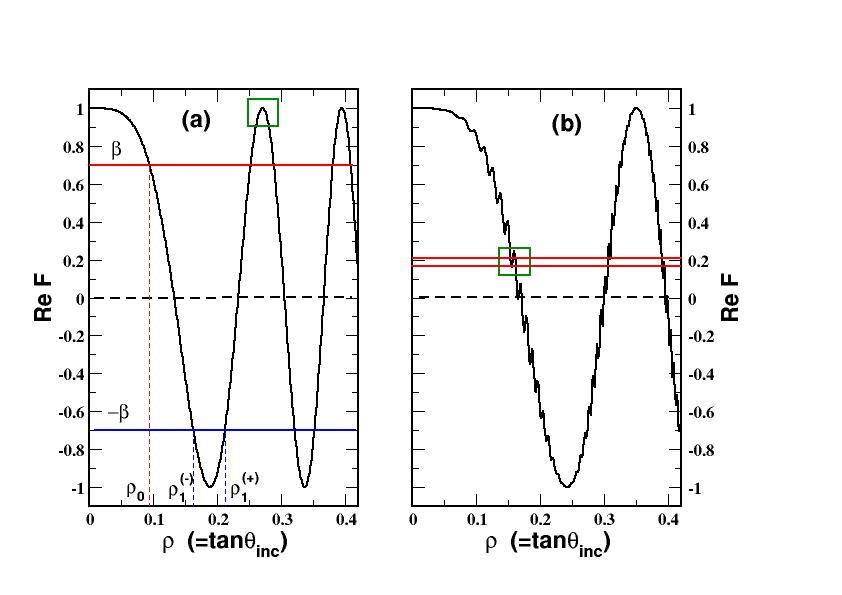
Figure 4: The real part of the function (69) that enter the left-hand side of Eq. (68) computed for (a) the cell filled with the NLC mixture E7 and (b) the KDP (potassium dihydrogen phosphate) birefringent crystal. The parameters are: (a) n=1.5246subscript𝑛perpendicular-to1.5246n_{\perp}=1.5246; n=1.7608subscript𝑛parallel-to1.7608n_{\parallel}=1.7608; nm=1.5subscript𝑛m1.5n_{\mathrm{m}}=1.5; d=110𝑑110d=110 μ𝜇\mum; and (b) n=1.5093subscript𝑛perpendicular-to1.5093n_{\perp}=1.5093; n=1.4683subscript𝑛parallel-to1.4683n_{\parallel}=1.4683; nm=1.0subscript𝑛m1.0n_{\mathrm{m}}=1.0; d=300𝑑300d=300 μ𝜇\mum.

The location of the Cν-points on the projection plane is determined by the polar coordinates: ρk(ν)superscriptsubscript𝜌𝑘𝜈\rho_{k}^{(\nu)} and ϕk(ν)superscriptsubscriptitalic-ϕ𝑘𝜈\phi_{k}^{(\nu)}, where k𝑘k is the numbering label. These can be found by solving the equation

|Ψν(ρ,ϕ)|=0subscriptΨ𝜈𝜌italic-ϕ0\displaystyle|\Psi_{\nu}(\rho,\phi)|=0 (62)

that generally has multiple solutions.

The case of linearly polarized wave with ϵell=0subscriptitalic-ϵell0\epsilon_{\mathrm{ell}}=0 provides another example of the polarization singularity where the handedness is undefined. The curves along which the polarization is linear are called the L-lines.

The transmitted wave is linearly polarized when the condition

|Ψ+(ρ,ϕ)|=|Ψ(ρ,ϕ)|subscriptΨ𝜌italic-ϕsubscriptΨ𝜌italic-ϕ\displaystyle|\Psi_{+}(\rho,\phi)|=|\Psi_{-}(\rho,\phi)| (63)

is satisfied. So, Eq. (63) describes loci of points forming the L-lines lying in the projection plane.

Refer to caption
Refer to caption
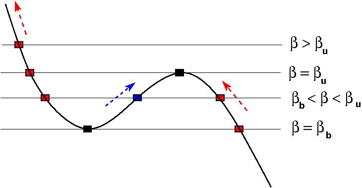
Figure 5: Schematic respresentation of creation and annihilation of C-points governed by saddle-node bifurcations of the solutions of Eq. (68) that take place within the areas marked by the boxes in Figs. 4(a) and 4(b). (a) C-points annihilate as the governing parameter β𝛽\beta passes through its critical value βcsubscript𝛽𝑐\beta_{c} in the immediate vicinity of unity. (b) Two successive bifurcations result in creation and annihilation of C-points at β=βb𝛽subscript𝛽𝑏\beta=\beta_{b} and β=βu𝛽subscript𝛽𝑢\beta=\beta_{u}, respectively.
Refer to caption
(a) ϵell(inc)=0.0superscriptsubscriptitalic-ϵellinc0.0\epsilon_{\mathrm{ell}}^{(\mathrm{inc})}=0.0
Refer to caption
(b) ϵell(inc)=0.01superscriptsubscriptitalic-ϵellinc0.01\epsilon_{\mathrm{ell}}^{(\mathrm{inc})}=0.01
Refer to caption
(c) ϵell(inc)=0.01superscriptsubscriptitalic-ϵellinc0.01\epsilon_{\mathrm{ell}}^{(\mathrm{inc})}=-0.01
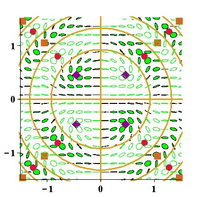
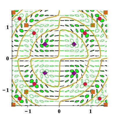
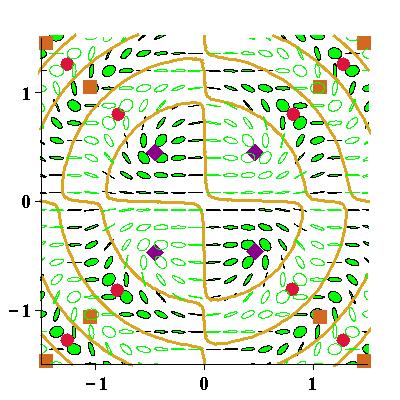
Figure 6: Polarization resolved conoscopic patterns computed as polarisation ellipse fields in the observation plane for the homeotropically oriented cell filled with the NLC mixture E7 at small values of the ellipticity: (a) ϵell(inc)=0.0superscriptsubscriptitalic-ϵellinc0.0\epsilon_{\mathrm{ell}}^{(\mathrm{inc})}=0.0, (b) ϵell(inc)=0.01superscriptsubscriptitalic-ϵellinc0.01\epsilon_{\mathrm{ell}}^{(\mathrm{inc})}=0.01, and (c) ϵell(inc)=0.01superscriptsubscriptitalic-ϵellinc0.01\epsilon_{\mathrm{ell}}^{(\mathrm{inc})}=-0.01. The parameters used in calculations are: the wavelength is λinc=632.8subscript𝜆inc632.8\lambda_{\mathrm{inc}}=632.8 nm; the polarization azimuth is ϕp(inc)=0superscriptsubscriptitalic-ϕ𝑝inc0\phi_{p}^{(\mathrm{inc})}=0; the cell thickness is d=110 μ𝑑110 𝜇d=110\text{ }\mum; the scale factor is r=5𝑟5r=5 mm; nm=1.5subscript𝑛m1.5n_{\mathrm{m}}=1.5, n=1.5246subscript𝑛perpendicular-to1.5246n_{\perp}=1.5246, and n=1.7608subscript𝑛parallel-to1.7608n_{\parallel}=1.7608. The C-points of the star, the lemon and the monstar types are marked by circles, diamonds and squares, respectively. L-lines are represented by solid lines. Left-handed and right-handed polarization is respectively indicated by solid and open ellipses.
Refer to caption
(a) ϵell(inc)=ϵ2(c)107superscriptsubscriptitalic-ϵellincsuperscriptsubscriptitalic-ϵ2𝑐superscript107\epsilon_{\mathrm{ell}}^{(\mathrm{inc})}=\epsilon_{2}^{(c)}-10^{-7}
Refer to caption
(b) ϵell(inc)=ϵ1(c)107superscriptsubscriptitalic-ϵellincsuperscriptsubscriptitalic-ϵ1𝑐superscript107\epsilon_{\mathrm{ell}}^{(\mathrm{inc})}=\epsilon_{1}^{(c)}-10^{-7}
Refer to caption
(c) ϵell(inc)=ϵ1(c)+106limit-fromsuperscriptsubscriptitalic-ϵellincsuperscriptsubscriptitalic-ϵ1𝑐superscript106\epsilon_{\mathrm{ell}}^{(\mathrm{inc})}-=\epsilon_{1}^{(c)}+10^{-6}
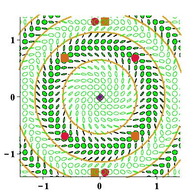
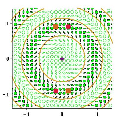
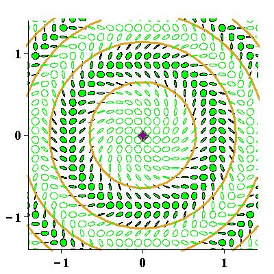
Figure 7: Polarization resolved conoscopic patterns of the homeotropically oriented NLC cell computed at different values of the ellipticity. Three cases are shown: (a) ϵ3(c)<ϵell(inc)<ϵ2(c)superscriptsubscriptitalic-ϵ3𝑐superscriptsubscriptitalic-ϵellincsuperscriptsubscriptitalic-ϵ2𝑐\epsilon_{3}^{(c)}<\epsilon_{\mathrm{ell}}^{(\mathrm{inc})}<\epsilon_{2}^{(c)}; (b) ϵ2(c)<ϵell(inc)<ϵ1(c)superscriptsubscriptitalic-ϵ2𝑐superscriptsubscriptitalic-ϵellincsuperscriptsubscriptitalic-ϵ1𝑐\epsilon_{2}^{(c)}<\epsilon_{\mathrm{ell}}^{(\mathrm{inc})}<\epsilon_{1}^{(c)}; (c) ϵ1(c)<ϵell(inc)<1superscriptsubscriptitalic-ϵ1𝑐superscriptsubscriptitalic-ϵellinc1\epsilon_{1}^{(c)}<\epsilon_{\mathrm{ell}}^{(\mathrm{inc})}<1. The list of other parameters is given in the caption of Fig. 6.

III.3 Ellipticity induced effects

III.3.1 C-points: creation and annihilation

When the director is normal to the substrates, the NLC cell is homeotropically aligned and dz=1subscript𝑑𝑧1d_{z}=1. In this case the transmission matrix (43) is diagonal and its elements in the circular basis are given by

tν,ν=t+,tν,ν=t,t±=(te±to)/2,formulae-sequencesubscript𝑡𝜈𝜈subscript𝑡formulae-sequencesubscript𝑡𝜈𝜈subscript𝑡subscript𝑡plus-or-minusplus-or-minussubscript𝑡𝑒subscript𝑡𝑜2\displaystyle t_{\nu,\nu}=t_{+},\quad t_{\nu,-\nu}=t_{-},\quad t_{\pm}=(t_{e}\pm t_{o})/2, (64)

where the transmission coefficients

te,o=te,o(qx)=[cos(δe,o)iγe,osin(δe,o)]1te,o(ρ)subscript𝑡𝑒𝑜subscript𝑡𝑒𝑜subscript𝑞𝑥superscriptdelimited-[]subscript𝛿𝑒𝑜𝑖subscript𝛾𝑒𝑜subscript𝛿𝑒𝑜1subscript𝑡𝑒𝑜𝜌\displaystyle t_{e,\,o}=t_{e,\,o}(q_{x})=\bigl{[}\cos(\delta_{e,\,o})-i\gamma_{e,\,o}\,\sin(\delta_{e,\,o})\bigr{]}^{-1}\equiv t_{e,\,o}(\rho) (65)

are expressed in terms of the phases

δe=qz(e)h=nn1n2qx2h,δo=qz(o)h=n2qx2hformulae-sequencesubscript𝛿𝑒superscriptsubscript𝑞𝑧𝑒subscript𝑛perpendicular-tosuperscriptsubscript𝑛parallel-to1superscriptsubscript𝑛parallel-to2superscriptsubscript𝑞𝑥2subscript𝛿𝑜superscriptsubscript𝑞𝑧𝑜superscriptsubscript𝑛perpendicular-to2superscriptsubscript𝑞𝑥2\displaystyle\delta_{e}=q_{z}^{(e)}h=n_{\perp}n_{\parallel}^{-1}\sqrt{n_{\parallel}^{2}-q_{x}^{2}}\,h,\quad\delta_{o}=q_{z}^{(o)}h=\sqrt{n_{\perp}^{2}-q_{x}^{2}}\,h (66)

and the amplitudes γe,osubscript𝛾𝑒𝑜\gamma_{e,\,o} defined in Eq. (46).

Owing to the cylindrical symmetry of the homeotropic structure, the transmission coefficients (65) do not depend on the azimuthal angle of the incidence plane ϕϕincitalic-ϕsubscriptitalic-ϕinc\phi\equiv\phi_{\mathrm{inc}}. From Eq. (III.2) another consequence of this symmetry is that the azimuth, ϕpϕp(inc)subscriptitalic-ϕ𝑝superscriptsubscriptitalic-ϕ𝑝inc\phi_{p}-\phi_{p}^{(\mathrm{inc})}, and the ellipticity of the transmitted wave depend only on the difference of the azimuthal angles: ϕϕp(inc)italic-ϕsuperscriptsubscriptitalic-ϕ𝑝inc\phi-\phi_{p}^{(\mathrm{inc})}. It follows that the sole effect of changing the polarization azimuth of the incident wave is the rotation of the polarization ellipse field by the angle ϕp(inc)superscriptsubscriptitalic-ϕ𝑝inc\phi_{p}^{(\mathrm{inc})}. So, we focus our attention on the effects governed by the ellipticity of the incident wave, ϵell(inc)superscriptsubscriptitalic-ϵellinc\epsilon_{\mathrm{ell}}^{(\mathrm{inc})}.

From Eqs. (III.2) and (64), the Cν-points may appear only if the condition

|tν,ν||tν,ν||t||t+|=1+νϵell(inc)1νϵell(inc)subscript𝑡𝜈𝜈subscript𝑡𝜈𝜈subscript𝑡subscript𝑡1𝜈superscriptsubscriptitalic-ϵellinc1𝜈superscriptsubscriptitalic-ϵellinc\displaystyle\frac{|t_{\nu,-\nu}|}{|t_{\nu,\nu}|}\equiv\frac{|t_{-}|}{|t_{+}|}=\frac{1+\nu\epsilon_{\mathrm{ell}}^{(\mathrm{inc})}}{1-\nu\epsilon_{\mathrm{ell}}^{(\mathrm{inc})}} (67)

is satisfied. Another form of this condition is

ReF(ρ)=ν2ϵell(inc)1+[ϵell(inc)]2ϵellμincβ,Re𝐹𝜌𝜈2superscriptsubscriptitalic-ϵellinc1superscriptdelimited-[]superscriptsubscriptitalic-ϵellinc2subscriptitalic-ϵellsubscript𝜇inc𝛽\displaystyle\mathop{\rm Re}\nolimits{F(\rho)}=-\nu\,\frac{2\epsilon_{\mathrm{ell}}^{(\mathrm{inc})}}{1+[\epsilon_{\mathrm{ell}}^{(\mathrm{inc})}]^{2}}\equiv\epsilon_{\mathrm{ell}}\,\mu_{\mathrm{inc}}\,\beta, (68)
F(ρ)=2te(ρ)to(ρ)|te(ρ)|2+|to(ρ)|2=exp(iΔ)cosh(ln|te|ln|to|),𝐹𝜌2subscript𝑡𝑒𝜌subscriptsuperscript𝑡𝑜𝜌superscriptsubscript𝑡𝑒𝜌2superscriptsubscript𝑡𝑜𝜌2𝑖Δsubscript𝑡𝑒subscript𝑡𝑜\displaystyle F(\rho)=\frac{2\,t_{e}(\rho)\,{t}^{\ast}_{o}(\rho)}{|t_{e}(\rho)|^{2}+|t_{o}(\rho)|^{2}}=\frac{\exp(i\Delta)}{\cosh(\ln|t_{e}|-\ln|t_{o}|)}, (69)

where β=2|ϵell(inc)|(1+[ϵell(inc)]2)1𝛽2superscriptsubscriptitalic-ϵellincsuperscript1superscriptdelimited-[]superscriptsubscriptitalic-ϵellinc21\beta=2|\epsilon_{\mathrm{ell}}^{(\mathrm{inc})}|(1+[\epsilon_{\mathrm{ell}}^{(\mathrm{inc})}]^{2})^{-1}, Δ=arg(teto)Δsubscript𝑡𝑒subscriptsuperscript𝑡𝑜\Delta=\arg(t_{e}{t}^{\ast}_{o}), ϵell=νsubscriptitalic-ϵell𝜈\epsilon_{\mathrm{ell}}=-\nu is the ellipticity of the Cν-point and μinc=sign(ϵell(inc))subscript𝜇incsignsuperscriptsubscriptitalic-ϵellinc\mu_{\mathrm{inc}}=\mathop{\rm sign}\nolimits(\epsilon_{\mathrm{ell}}^{(\mathrm{inc})}) is the handedness (helicity) of the incident wave. Solutions of equation (68) define the radii of circles containing the C-points.

Plots depicted in Fig. 4 demonstrate non-monotonic behaviour of the function ReFRe𝐹\mathop{\rm Re}\nolimits F that enter the left-hand side of Eq. (68).

The experimentally relevant case of the nematic cell filled with the LC mixture E7 is shown in Fig. 4(a). It is characterized by the weak anisotropy of the transmission amplitudes |te|subscript𝑡𝑒|t_{e}| and |to|subscript𝑡𝑜|t_{o}|, so that |1|te|/|to||<1041subscript𝑡𝑒subscript𝑡𝑜superscript104|1-|t_{e}|/|t_{o}||<10^{-4} for the incidence angles up to 606060 degrees. For such cells, the phase of the function (69), ΔΔ\Delta, can be approximated by the difference in optical path of the ordinary and extraordinary waves, δ=δeδo𝛿subscript𝛿𝑒subscript𝛿𝑜\delta=\delta_{e}-\delta_{o}. So, the formula

F(ρ)F0(ρ)=exp(iδ),δ=δeδo,formulae-sequence𝐹𝜌subscript𝐹0𝜌𝑖𝛿𝛿subscript𝛿𝑒subscript𝛿𝑜\displaystyle F(\rho)\approx F_{0}(\rho)=\exp(i\delta),\quad\delta=\delta_{e}-\delta_{o}, (70)

provides a high accuracy approximation for the expression (69) and, for the LC mixture E7, the deviation max|FF0|𝐹subscript𝐹0\max|F-F_{0}| can be estimated to be better than 5.0×1045.0superscript1045.0\times 10^{-4}.

The radii of the circles with the C-points. can now be accurately located by solving the approximate equation cosδ=±β𝛿plus-or-minus𝛽\cos\delta=\pm\beta obtained from Eq. (68) by using the expression (70). The result can written as two sequences of radii

|δ(ρ0)|arccos(β),|δ(ρk(±))|±arccos(β)+πk,k=1,,N,formulae-sequence𝛿subscript𝜌0𝛽formulae-sequence𝛿superscriptsubscript𝜌𝑘plus-or-minusplus-or-minus𝛽𝜋𝑘𝑘1𝑁\displaystyle|\delta(\rho_{0})|\approx\arccos(\beta),\quad|\delta(\rho_{k}^{(\pm)})|\approx\pm\arccos(\beta)+\pi k,\quad k=1,\ldots,N, (71)

where N𝑁N is determined by the number of solutions and the circles of each sequence, ρk(+)superscriptsubscript𝜌𝑘\rho_{k}^{(+)} and ρk()superscriptsubscript𝜌𝑘\rho_{k}^{(-)}, are numbered by the non-negative integer k𝑘k in non-decreasing order of size, so that ρ0ρ0(±)ρ1()ρ1(+)ρk()ρk(+)subscript𝜌0superscriptsubscript𝜌0plus-or-minussuperscriptsubscript𝜌1superscriptsubscript𝜌1superscriptsubscript𝜌𝑘superscriptsubscript𝜌𝑘\rho_{0}\equiv\rho_{0}^{(\pm)}\leq\rho_{1}^{(-)}\leq\rho_{1}^{(+)}\ldots\leq\rho_{k}^{(-)}\leq\rho_{k}^{(+)}\leq\ldots.

At ρ=ρk(±)𝜌superscriptsubscript𝜌𝑘plus-or-minus\rho=\rho_{k}^{(\pm)}, there is a pair of the C-points on each circle of the radius ρk(±)superscriptsubscript𝜌𝑘plus-or-minus\rho_{k}^{(\pm)} with the ellipticity and the azimuthal angles given by

ϵell|ρ=ρk(α)=(1)kμincμk,k=0,,N,formulae-sequenceevaluated-atsubscriptitalic-ϵell𝜌superscriptsubscript𝜌𝑘𝛼superscript1𝑘subscript𝜇incsubscript𝜇𝑘𝑘0𝑁\displaystyle\epsilon_{\mathrm{ell}}\Bigr{|}_{\rho=\rho_{k}^{(\alpha)}}=(-1)^{k}\mu_{\mathrm{inc}}\equiv\mu_{k},\quad k=0,\ldots,N, (72)
ϕ±k(α)=ϕp(inc)±π/2μk2arg[t+t]ρ=ρk(α),\displaystyle\phi_{\pm k}^{(\alpha)}=\phi_{p}^{(\mathrm{inc})}\pm\pi/2-\frac{\mu_{k}}{2}\arg\Bigl{[}{t}^{\ast}_{+}t_{-}\Bigr{]}_{\rho=\rho_{k}^{(\alpha)}}, (73)

where ρ0(α)ρ0superscriptsubscript𝜌0𝛼subscript𝜌0\rho_{0}^{(\alpha)}\equiv\rho_{0} and α{+,}𝛼\alpha\in\{+,-\}.

The symmetric arrangment of the C-points is a consequence of the symmetry relation

|Ψν(ρ,ψ)|=|Ψν(ρ,π+ψ)|subscriptΨ𝜈𝜌𝜓subscriptΨ𝜈𝜌𝜋𝜓\displaystyle|\Psi_{\nu}(\rho,\psi)|=|\Psi_{\nu}(\rho,\pi+\psi)| (74)

for the amplitudes (III.2).

We can now substitute Eq. (III.2) into the expression for the index (61) and use the relations (64) and (68) to recast the result into the form of the index formula

IC=12sign[ρReF(ρ)]ρ=ρk(±)=±(1)k2,k=0,N,formulae-sequencesubscript𝐼𝐶12signsubscriptdelimited-[]subscript𝜌Re𝐹𝜌𝜌superscriptsubscript𝜌𝑘plus-or-minusplus-or-minussuperscript1𝑘2𝑘0𝑁\displaystyle I_{C}=-\frac{1}{2}\,\mathop{\rm sign}\nolimits\Bigl{[}\partial_{\rho}\mathop{\rm Re}\nolimits{F(\rho)}\Bigr{]}_{\rho=\rho_{k}^{(\pm)}}=\frac{\pm(-1)^{k}}{2}\,,\quad k=0,\ldots N, (75)

where the second equality follows because ReFRe𝐹\mathop{\rm Re}\nolimits F is an oscillating function of ρ𝜌\rho and F(0)=1𝐹01F(0)=1.

Interestingly, Eq. (75) relates the index of C-points and derivatives of the transmission coefficients with respect to the incidence angle (ρf=cos2θincf/θincsubscript𝜌𝑓superscript2subscript𝜃inc𝑓subscript𝜃inc\partial_{\rho}f=\cos^{2}\theta_{\mathrm{inc}}\,\partial f/\partial\theta_{\mathrm{inc}}). The index is determined by the circle number k𝑘k and alternates in sign starting from IC=+1/2subscript𝐼𝐶12I_{C}=+1/2 which is the index of two C-points symetrically arranged in the vicinity of the origin.

So, the pair of C-points lying on the smallest circle of the radius ρ0subscript𝜌0\rho_{0} can either be of lemon or monstar types. Interestingly, when β𝛽\beta approaches unity and the incident light becomes circularly polarized, the radius ρ0subscript𝜌0\rho_{0} vanishes and the C-points merge into one C-point of the index +11+1.

This is the limiting case where the incident light is circular polarized with ϵell(inc)=±1superscriptsubscriptitalic-ϵellincplus-or-minus1\epsilon_{\mathrm{ell}}^{(\mathrm{inc})}=\pm 1 and a C-point may develop provided that the transmission coefficients meet the isotropy condition: te=±tosubscript𝑡𝑒plus-or-minussubscript𝑡𝑜t_{e}=\pm t_{o}. As it can be seen from Eq. (65) we have te=tosubscript𝑡𝑒subscript𝑡𝑜t_{e}=t_{o} for the case of normal incidence with qx=sinθinc=0subscript𝑞𝑥subscript𝜃inc0q_{x}=\sin\theta_{\mathrm{inc}}=0. The corresponding C-point is located at the origin and, as it was discussed earlier, its index ICsubscript𝐼𝐶I_{C} equals +11+1.

At this stage, however, it remains unclear if the above-mentioned C-point is unique. In order to clarify this, we shall look more closely at the events that happen when the ellipticity parameter β𝛽\beta defined in Eq. (68) varies from zero to unity. At β=0𝛽0\beta=0, the incident light is in the state of linear polarization with ϵell(inc)=0superscriptsubscriptitalic-ϵellinc0\epsilon_{\mathrm{ell}}^{(\mathrm{inc})}=0, whereas the incident wave is circular polarized with |ϵell(inc)|=1superscriptsubscriptitalic-ϵellinc1|\epsilon_{\mathrm{ell}}^{(\mathrm{inc})}|=1 at β=1𝛽1\beta=1.

The case of linearly polarized incident waves was previously studied in Refs. Kiselev (2006, 2007). Fig. 6(a) shows the polarization resolved angular pattern as the polarization ellipse field computed at β=0𝛽0\beta=0. It can be seen that we have a sequence of N+1𝑁1N+1 concentric circles each containing two pairs of symmetrically arranged C-points. The index and the handedness of the C-points alternate in sign along the radial direction. The C-points on the circle of the smallest radius, ρ=ρ0𝜌subscript𝜌0\rho=\rho_{0}, corresponding to the direction close to the normal incidence are found to be of the lemon type with the index equal to +1/212+1/2.

Algebraically, from Eq. (71) it follows that the difference between the radii of the C-points ρk(+)superscriptsubscript𝜌𝑘\rho_{k}^{(+)} and ρk+1()superscriptsubscript𝜌𝑘1\rho_{k+1}^{(-)}, where k=0,,N𝑘0𝑁k=0,\ldots,N, vanishes with the ellipticity ϵell(inc)superscriptsubscriptitalic-ϵellinc\epsilon_{\mathrm{ell}}^{(\mathrm{inc})} approaching zero. So, at ϵell(inc)=0superscriptsubscriptitalic-ϵellinc0\epsilon_{\mathrm{ell}}^{(\mathrm{inc})}=0, the angular polarization structure is characterized by the presence of degeneracy which is a consequence of the additional symmetry relation

|Ψν(ρ,ψ)|=|Ψν(ρ,πψ)|.subscriptΨ𝜈𝜌𝜓subscriptΨ𝜈𝜌𝜋𝜓\displaystyle|\Psi_{\nu}(\rho,\psi)|=|\Psi_{-\nu}(\rho,\pi-\psi)|. (76)

The symmetry-breaking effects due to non-vanishing ellipticity of the incident wave are illustrated in Figs. 6(b) and 6(c) for small values of ϵell(inc)superscriptsubscriptitalic-ϵellinc\epsilon_{\mathrm{ell}}^{(\mathrm{inc})}. This is the case when the relation (76) breaks down removing the above degeneracy, so that ρk(+)<ρk+1()superscriptsubscript𝜌𝑘superscriptsubscript𝜌𝑘1\rho_{k}^{(+)}<\rho_{k+1}^{(-)} at ϵell(inc)0superscriptsubscriptitalic-ϵellinc0\epsilon_{\mathrm{ell}}^{(\mathrm{inc})}\neq 0.

As is schematically illustrated by Fig. 5, there is another type of degeneracy which takes place when the ellipticity parameter β𝛽\beta reaches a local maximum of the function ReFRe𝐹\mathop{\rm Re}\nolimits F such as one marked by box in Fig. 4(a). In contrast to the above-discussed case of linear polarization, the number of C-points changes as the parameter β𝛽\beta and the ellipticity ϵell(inc)superscriptsubscriptitalic-ϵellinc\epsilon_{\mathrm{ell}}^{(\mathrm{inc})} pass through their critical values, βcsubscript𝛽𝑐\beta_{c} and ϵ(c)superscriptitalic-ϵ𝑐\epsilon^{(c)}.

The picture shown in Fig. 5 is typical of a saddle-node (tangent) bifuraction Hohenberg and Halperin (1977); Devaney (1989). Such bifurcations occur at the incidence angles represented by the values of the radii (see Eq. (56)) at local extrema of the real part of the function (69). By applying the approximation (70), these radii can be estimated from the solutions of the equation

|δ(ρk(c))|πk,k=0,,Nformulae-sequence𝛿superscriptsubscript𝜌𝑘𝑐𝜋𝑘𝑘0𝑁\displaystyle|\delta(\rho_{k}^{(c)})|\approx\pi k,\quad k=0,\ldots,N (77)

obtained from Eq. (71) by setting arccos(β)=0𝛽0\arccos(\beta)=0.

Given the critical value of the radius, ρ=ρk(c)𝜌superscriptsubscript𝜌𝑘𝑐\rho=\rho_{k}^{(c)}, we can use Eq. (68) to deduce the relations

βk(c)=|ReF(ρk(c))|,βk(c)ϵk(c)=1+1[βk(c)]2formulae-sequencesuperscriptsubscript𝛽𝑘𝑐Re𝐹superscriptsubscript𝜌𝑘𝑐superscriptsubscript𝛽𝑘𝑐superscriptsubscriptitalic-ϵ𝑘𝑐11superscriptdelimited-[]superscriptsubscript𝛽𝑘𝑐2\displaystyle\beta_{k}^{(c)}=\bigl{|}\mathop{\rm Re}\nolimits{F(\rho_{k}^{(c)})}\bigr{|},\quad\beta_{k}^{(c)}\epsilon_{k}^{(c)}=-1+\sqrt{1-\left[\beta_{k}^{(c)}\right]^{2}} (78)

and to compute the corresponding values of the parameter β𝛽\beta and the ellipticity: β=βk(c)𝛽superscriptsubscript𝛽𝑘𝑐\beta=\beta_{k}^{(c)} and |ϵell(inc)|=ϵk(c)superscriptsubscriptitalic-ϵellincsuperscriptsubscriptitalic-ϵ𝑘𝑐|\epsilon_{\mathrm{ell}}^{(\mathrm{inc})}|=\epsilon_{k}^{(c)}. It is also not difficult to show that ρ0(c)=0superscriptsubscript𝜌0𝑐0\rho_{0}^{(c)}=0 and ρk()ρk(c)ρk(+)superscriptsubscript𝜌𝑘superscriptsubscript𝜌𝑘𝑐superscriptsubscript𝜌𝑘\rho_{k}^{(-)}\leq\rho_{k}^{(c)}\leq\rho_{k}^{(+)}.

Our analysis suggests that the ellipse field undergoes a sequence of tangent bifurcations as the magnitude of the ellipticity |ϵell(inc)|superscriptsubscriptitalic-ϵellinc|\epsilon_{\mathrm{ell}}^{(\mathrm{inc})}| increases from zero to unity. There are two pairs of the C-points with ρ=ρk()𝜌superscriptsubscript𝜌𝑘\rho=\rho_{k}^{(-)} and ρ=ρk(+)𝜌superscriptsubscript𝜌𝑘\rho=\rho_{k}^{(+)} that merge and, subsequently, annihilate as the governing parameter passes through the bifurcation point with |ϵell(inc)|=ϵk(c)superscriptsubscriptitalic-ϵellincsuperscriptsubscriptitalic-ϵ𝑘𝑐|\epsilon_{\mathrm{ell}}^{(\mathrm{inc})}|=\epsilon_{k}^{(c)} and ρk(+)=ρk()superscriptsubscript𝜌𝑘superscriptsubscript𝜌𝑘\rho_{k}^{(+)}=\rho_{k}^{(-)}.

In addition, an important consequence of the index formula (75) is that the indicies of the C-points involved in a tangent bifurcation differ only in sign, so that the total sum of indicies remains intact. Obviously, this result agrees with the conservation law of the total topological index.

Note, however, that, within the approximation (70), the C-points cannot merge and annihilate provided the incident wave is not circular polarized. Mathematically, the difficulty is that, for the approximate function cosδ𝛿\cos\delta, the critical values of the ellipticity are all equal to unity, βk(c)=ϵk(c)=1superscriptsubscript𝛽𝑘𝑐superscriptsubscriptitalic-ϵ𝑘𝑐1\beta_{k}^{(c)}=\epsilon_{k}^{(c)}=1. So, we arrive at the conclusion that the difference 1ϵk(c)1superscriptsubscriptitalic-ϵ𝑘𝑐1-\epsilon_{k}^{(c)} is determined by the accuracy of the approximation (70).

For the cell filled with the LC mixture E7, the fisrt three critical values of the ellipticity ϵ3(c)<ϵ2(c)<ϵ1(c)superscriptsubscriptitalic-ϵ3𝑐superscriptsubscriptitalic-ϵ2𝑐superscriptsubscriptitalic-ϵ1𝑐\epsilon_{3}^{(c)}<\epsilon_{2}^{(c)}<\epsilon_{1}^{(c)} turned out to be very close to unity: 1ϵ1(c)1.22×1061superscriptsubscriptitalic-ϵ1𝑐1.22superscript1061-\epsilon_{1}^{(c)}\approx 1.22\times 10^{-6}, 1ϵ2(c)1.17×1051superscriptsubscriptitalic-ϵ2𝑐1.17superscript1051-\epsilon_{2}^{(c)}\approx 1.17\times 10^{-5} and 1ϵ3(c)4.16×1051superscriptsubscriptitalic-ϵ3𝑐4.16superscript1051-\epsilon_{3}^{(c)}\approx 4.16\times 10^{-5}. The polarization resolved angular patterns presented in Fig. 7 are computed at the three different values of ϵell(inc)superscriptsubscriptitalic-ϵellinc\epsilon_{\mathrm{ell}}^{(\mathrm{inc})}: (a) ϵ3(c)<ϵell(inc)=ϵ2(c)107<ϵ2(c)superscriptsubscriptitalic-ϵ3𝑐superscriptsubscriptitalic-ϵellincsuperscriptsubscriptitalic-ϵ2𝑐superscript107superscriptsubscriptitalic-ϵ2𝑐\epsilon_{3}^{(c)}<\epsilon_{\mathrm{ell}}^{(\mathrm{inc})}=\epsilon_{2}^{(c)}-10^{-7}<\epsilon_{2}^{(c)}; (b) ϵ2(c)<ϵell(inc)=ϵ1(c)107<ϵ1(c)superscriptsubscriptitalic-ϵ2𝑐superscriptsubscriptitalic-ϵellincsuperscriptsubscriptitalic-ϵ1𝑐superscript107superscriptsubscriptitalic-ϵ1𝑐\epsilon_{2}^{(c)}<\epsilon_{\mathrm{ell}}^{(\mathrm{inc})}=\epsilon_{1}^{(c)}-10^{-7}<\epsilon_{1}^{(c)}; (c) ϵ1(c)<ϵell(inc)=ϵ1(c)+106<1superscriptsubscriptitalic-ϵ1𝑐superscriptsubscriptitalic-ϵellincsuperscriptsubscriptitalic-ϵ1𝑐superscript1061\epsilon_{1}^{(c)}<\epsilon_{\mathrm{ell}}^{(\mathrm{inc})}=\epsilon_{1}^{(c)}+10^{-6}<1. The pairs of the C-points with k=3𝑘3k=3, k=2𝑘2k=2 and k=1𝑘1k=1 are shown to coalesce and disappear in succession as the ellipticity passes sequentially through ϵ3(c)superscriptsubscriptitalic-ϵ3𝑐\epsilon_{3}^{(c)}, ϵ2(c)superscriptsubscriptitalic-ϵ2𝑐\epsilon_{2}^{(c)} and ϵ1(c)superscriptsubscriptitalic-ϵ1𝑐\epsilon_{1}^{(c)}.

So, in the limit of circular polarization with ϵell(inc)=1superscriptsubscriptitalic-ϵellinc1\epsilon_{\mathrm{ell}}^{(\mathrm{inc})}=1, we have the pattern where the only C-point is located at the origin. The index of this C-point is IC=+1subscript𝐼𝐶1I_{C}=+1. This result is in agreement with the Euler-Poincaré theorem linking the Euler characteristics, χ𝜒\chi, of a two-dimesional manifold and the total topological charge (index) of a smooth vector field on the manifold Monastyrsky (1993). In our case, it can be concluded that χ=2IC𝜒2subscript𝐼𝐶\chi=2I_{C} is the total index, where χ=+2𝜒2\chi=+2 is the Euler characteristics of a sphere.

So far, we considered bifurcations at the local extrema that, according to Eq. (77), are in one-to-one correspondence with the extrema of the function ReF0=cosδResubscript𝐹0𝛿\mathop{\rm Re}\nolimits{F_{0}}=\cos\delta. Thus, such birfucations are governed by the phase difference between ordinary and extraordinary waves, δ=δeδo𝛿subscript𝛿𝑒subscript𝛿𝑜\delta=\delta_{e}-\delta_{o}. As is shown in Fig. 7, they are typically characterized by extremely small differences between unity and the critical values of the ellipticity. For this reason they cannot be detected experimentally.

From the above discussion it can be inferred that the critical values might be lowered only if the approximation (70) does not work well. In particular, this is the case for the graph of ReFRe𝐹\mathop{\rm Re}\nolimits{F} plotted in Fig. 4(b) where the anisotropic material is represented by the KDP (potassium dihydrogen phosphate) birefringent crystal. The deviation max|FF0|𝐹subscript𝐹0\max|F-F_{0}| can be estimated at about 7.0×1027.0superscript1027.0\times 10^{-2}, so that max[1ϵk(c)]0.021superscriptsubscriptitalic-ϵ𝑘𝑐0.02\max\bigl{[}1-\epsilon_{k}^{(c)}\bigr{]}\approx 0.02.

The curve shown in Fig. 4(b) also demonstrates that the breakdown of the approximation (70) may manifest itself in additional extrema formed away from the neighborhood of unity. As is illustrated in Fig. 5 for the region marked by the box in Fig. 4(b), these local extrema result in two successive tangent bifurcations leading to creation and annihilation of two different pairs of the C-points.

In contrast to the extrema described by the phase difference δ𝛿\delta, this is the multireflection which is primarily responsible for additional small-scale oscillations. Typically, it is a challenging task to resolve accurately these ripple-like and noisy oscillations in polarimetry measurements.

III.3.2 Avoided L-line crossings

Now we pass on to discussing the L-lines which are the curves of linear polarization in the observation plane. Analytically, substituting Eq. (III.2) into the relation (63) and using the matrix elements (64) give the equation

2ϵell(inc)ReF(ρ)+(1[ϵell(inc)]2)sin(2ψ)ImF(ρ)=02superscriptsubscriptitalic-ϵellincRe𝐹𝜌1superscriptdelimited-[]superscriptsubscriptitalic-ϵellinc22𝜓Im𝐹𝜌0\displaystyle 2\epsilon_{\mathrm{ell}}^{(\mathrm{inc})}\mathop{\rm Re}\nolimits{F(\rho)}+(1-[\epsilon_{\mathrm{ell}}^{(\mathrm{inc})}]^{2})\sin(2\psi)\,\mathop{\rm Im}\nolimits{F(\rho)}=0 (79)

describing L-lines for the case of the homeotropically aligned NLC cell.

We begin with the results for the case of linearly polarized incident waves studied in Refs. Kiselev (2006, 2007). At ϵell(inc)=0superscriptsubscriptitalic-ϵellinc0\epsilon_{\mathrm{ell}}^{(\mathrm{inc})}=0, from Eq. (79) there are two straight lines of linear polarization: ϕ=ϕp(inc)italic-ϕsuperscriptsubscriptitalic-ϕ𝑝inc\phi=\phi_{p}^{(\mathrm{inc})} and ϕ=ϕp(inc)+π/2italic-ϕsuperscriptsubscriptitalic-ϕ𝑝inc𝜋2\phi=\phi_{p}^{(\mathrm{inc})}+\pi/2, where the polarization vectors of incident and transmitted waves are parallel, ϕp(tr)ϕp=ϕp(inc)superscriptsubscriptitalic-ϕ𝑝trsubscriptitalic-ϕ𝑝superscriptsubscriptitalic-ϕ𝑝inc\phi_{p}^{(\mathrm{tr})}\equiv\phi_{p}=\phi_{p}^{(\mathrm{inc})}. Other L-lines are circles separating the circles of C-points. Interestingly, the radii of the circles, ρk(L)superscriptsubscript𝜌𝑘𝐿\rho_{k}^{(L)}, can be found as the solutions of Eq. (77) with k=1,N𝑘1𝑁k=1,\ldots N.

When k𝑘k is even, it can be concluded that, similar to the straight L-lines, ϕpϕp(inc)subscriptitalic-ϕ𝑝superscriptsubscriptitalic-ϕ𝑝inc\phi_{p}\approx\phi_{p}^{(\mathrm{inc})}. If k𝑘k is odd, the polarization vector of the transmitted wave rotates with the azimuthal angle of the incidence plane and ϕpϕp(inc)+2ϕsubscriptitalic-ϕ𝑝superscriptsubscriptitalic-ϕ𝑝inc2italic-ϕ\phi_{p}\approx\phi_{p}^{(\mathrm{inc})}+2\phi.

The structure of the L-lines at β=0𝛽0\beta=0 is shown in Fig. 6(a) where the L-lines are represented by the solid lines bounding the regions of left- and right-handed polarization. As it was discussed in the preceding subsection, the case of linear polarization possesses additional symmetry described by the relation (76). This symmetry is broken at non-zero values of the ellipticity and the case of linear polarization is structurally unstable.

In Fig. 6(b) and Fig. 6(c), we show that even small values of the ellipticity, ϵell(inc)superscriptsubscriptitalic-ϵellinc\epsilon_{\mathrm{ell}}^{(\mathrm{inc})}, change the structure of the intersecting L-lines depicted in Fig. 6(a) into a family of non-intersecting closed L-lines. The figures clearly demonstrate what might be called, by analogy with the well-known avoided level crossings in the quantum mechanics, the effect of avoided L-line crossings

The closed L-lines gradually evolve into the circles as the ellipticity approaches the limit of circular polarization with |ϵell(inc)|=1superscriptsubscriptitalic-ϵellinc1|\epsilon_{\mathrm{ell}}^{(\mathrm{inc})}|=1. The radii of the C-circles ρk(L)superscriptsubscript𝜌𝑘𝐿\rho_{k}^{(L)} can be found by solving the equation: ReF(ρ)=0Re𝐹𝜌0\mathop{\rm Re}\nolimits{F}(\rho)=0. It follows that ρk()superscriptsubscript𝜌𝑘\rho_{k}^{(-)} at ϵell(inc)=0superscriptsubscriptitalic-ϵellinc0\epsilon_{\mathrm{ell}}^{(\mathrm{inc})}=0 is equal to ρk(L)superscriptsubscript𝜌𝑘𝐿\rho_{k}^{(L)} at |ϵell(inc)|=1superscriptsubscriptitalic-ϵellinc1|\epsilon_{\mathrm{ell}}^{(\mathrm{inc})}|=1. So, we have a family of the concentric circles describing both the C-points for linearly polarized incident waves (see Fig. 6(a)) and the L-lines for circular polarized incident waves. (see Fig. 7).
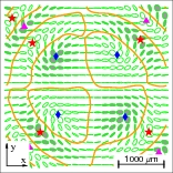
Refer to caption
(a) Experiment at ϵell(inc)=0.0superscriptsubscriptitalic-ϵellinc0.0\epsilon_{\mathrm{ell}}^{(\mathrm{inc})}=0.0
Refer to caption
(b) Theory at ϵell(inc)=0.0superscriptsubscriptitalic-ϵellinc0.0\epsilon_{\mathrm{ell}}^{(\mathrm{inc})}=0.0
Figure 8: (a) Experimentally measured and (b) theoretically computed fields of polarization ellipses in the observation plane for the homeotropically aligned cell of the thickness d=110𝑑110d=110 μ𝜇\mum  filled with the NLC mixture E7. The incident wave is linearly polarized with the polarization azimuth ϕp(inc)=0superscriptsubscriptitalic-ϕ𝑝inc0\phi_{p}^{(\mathrm{inc})}=0. The C-points of the star, the lemon and the monstar types are marked by stars, diamonds and triangles, respectively. L-lines are represented by solid lines. Left-handed and right-handed polarization is respectively indicated by solid and open ellipses.
Refer to caption
(a) Experiment at ϵell(inc)=0.26superscriptsubscriptitalic-ϵellinc0.26\epsilon_{\mathrm{ell}}^{(\mathrm{inc})}=0.26
Refer to caption
(b) Theory at ϵell(inc)=0.26superscriptsubscriptitalic-ϵellinc0.26\epsilon_{\mathrm{ell}}^{(\mathrm{inc})}=0.26
Figure 9: (a) Experimentally measured and (b) theoretically computed fields of polarization ellipses for the homeotropically aligned cell filled with the NLC mixture E7. The ellipticity of the incident light is ϵell(inc)=0.26superscriptsubscriptitalic-ϵellinc0.26\epsilon_{\mathrm{ell}}^{(\mathrm{inc})}=0.26.
Refer to caption
(a) Experiment at ϵell(inc)=0.65superscriptsubscriptitalic-ϵellinc0.65\epsilon_{\mathrm{ell}}^{(\mathrm{inc})}=0.65
Refer to caption
(b) Theory at ϵell(inc)=0.65superscriptsubscriptitalic-ϵellinc0.65\epsilon_{\mathrm{ell}}^{(\mathrm{inc})}=0.65
Figure 10: (a) Experimentally measured and (b) theoretically computed fields of polarization ellipses for the homeotropically aligned cell filled with the NLC mixture E7. The ellipticity of the incident wave is ϵell(inc)=0.65superscriptsubscriptitalic-ϵellinc0.65\epsilon_{\mathrm{ell}}^{(\mathrm{inc})}=0.65.

IV Results and discussion

The analytical results presented in the previous section completely characterize the polarization resolved angular patterns of light transmitted through the NLC cell for the homeotropic orientational structure in terms of the polarization singularities. These patterns can be conveniently represented as the fields of polarization ellipses and characterize the polarization structure behind the conoscopic images measured in experiments with two crossed polarizers.

After computing loci of the C-points and the L-lines, we have deduced a simple formula for the index of the C-points (75) and studied what happen to the polarization singularities if the ellipticity and the polarization azimuth of the incident wave vary. It turned out that the C-points may appear and disappear when the pattern undergoes bifurcations at some critical values of the ellipticity. In addition, the patterns formed in the neighborhood of zero ellipticity (learly polarized incident light) are characterized by the appearance of avoided L-line crossings.

Now we compare the experimentally measured and the theoretically calculated polarization resolved angular patterns for the homeotropically oriented NLC cell. These patterns are shown in Figs. 810 as the fields of polarization ellipses in the observation plane where the polar coordinates are defined in Eq. (56) and the scale factor r𝑟r is taken to be 555 mm. The parameters used in our calculations are described in Sec. II. They are also listed in the caption of Fig. 6.

In Fig. 8, we present the results obtained for the linearly polarized wave with ϵell(inc)=0.0superscriptsubscriptitalic-ϵellinc0.0\epsilon_{\mathrm{ell}}^{(\mathrm{inc})}=0.0, whereas the cases of elliptically polarized incident light with ϵell(inc)=0.26superscriptsubscriptitalic-ϵellinc0.26\epsilon_{\mathrm{ell}}^{(\mathrm{inc})}=0.26 and ϵell(inc)=0.65superscriptsubscriptitalic-ϵellinc0.65\epsilon_{\mathrm{ell}}^{(\mathrm{inc})}=0.65 are shown in Fig. 9 and Fig. 10, respectively. As is evident from the figures, the C-points are arranged in chains formed by four rays along which they alternate in sign of the handedness and of the index. The L-lines are typically represented by the closed curves separating the regions of different polarization handedness. It is also clear that the predictions of the theory discussed in Sec. III.3 are in good agreement with the experimental data.

In addition, by making a comparison between the patterns with different values of ellipticity we arrive at the conclusion that, when the ellipticity changes, the C-points mainly move along the radial direction and their azimuthal angles remain approximately constant. Theoretically, it can be shown that, at ϕp(inc)=0superscriptsubscriptitalic-ϕ𝑝inc0\phi_{p}^{(\mathrm{inc})}=0, the azimuthal angle |ϕ±k(α)|superscriptsubscriptitalic-ϕplus-or-minus𝑘𝛼|\phi_{\pm k}^{(\alpha)}| given by Eq. (73) does not depart appreciably from π/4𝜋4\pi/4 provided the magnitude of the ellipticity |ϵell(inc)|superscriptsubscriptitalic-ϵellinc|\epsilon_{\mathrm{ell}}^{(\mathrm{inc})}| is not in the immediate vicinity of unity.

By contrast, as is shown in Fig. 7, annihilation of the C-points is accompanied by drastic changes in the azimuth of the C-points, whereas the radius is very close to its critical value defined in Eq. (77).

The geometric rearrangements and transformations studied in this paper might be regarded as pseudo-dynamics of the polarization ellipse fields with the ellipticity served as a “time” parameter. In three-dimensional space, phase singularity lines, whose geometry depends on a “time” parameter were recently investigated in Ref. Berry and Dennis (2007)

In conclusion, we note that the homeotropic alignment presents the simplest case of anisotropic orientational structure. Our theoretical analysis can be extended to more complicated cases involving both uniaxial and biaxial anisotropies by using the analytical results presented in Appendix A. These results will be published elsewhere.

Acknowledgements.
This work was partially supported by CERG Grant No. 612406 and by STCU Grant No. 4687.

Appendix A Operator of evolution

The equations (36) and (38) express the transmission and reflection matrices in terms of the linking matrix (34) which is determined by the evolution operator (26). In the case of uniform anisotropy, the operator can be computed as the evolution matrix (39) expressed in terms of the eigenvalues and the eigenvectors (40) of the matrix (25).

In this section we consider how the eigenvalue problem can be solved using the basis of eigenmodes (normal modes) in a uniformly anisotropic medium. These eigenmodes are known to be linearly polarized plane waves characterized by the 𝐤^^𝐤\hat{\mathbf{k}} dependent refractive indices Born and Wolf (1980); Yariv and Yeh (1984); Azzam and Bashara (1977).

A.1 Orthogonality relations

From Eqs. (25a)– (25d), if the dielectric tensor 𝜺𝜺\boldsymbol{\varepsilon} is symmetric, ϵij=ϵjisubscriptitalic-ϵ𝑖𝑗subscriptitalic-ϵ𝑗𝑖\epsilon_{ij}=\epsilon_{ji}, we deduce the relations for the block matrices

𝐌12T=𝐌12,𝐌21T=𝐌21,𝐌11T=𝐌22formulae-sequencesubscriptsuperscript𝐌𝑇12subscript𝐌12formulae-sequencesubscriptsuperscript𝐌𝑇21subscript𝐌21subscriptsuperscript𝐌𝑇11subscript𝐌22\displaystyle{\mathbf{M}}^{T}_{12}=\mathbf{M}_{12},\quad{\mathbf{M}}^{T}_{21}=\mathbf{M}_{21},\quad{\mathbf{M}}^{T}_{11}=\mathbf{M}_{22} (80)

giving the symmetry identity

𝐌T=𝐆𝐌𝐆,𝐆=(𝟎𝐈2𝐈2𝟎)formulae-sequencesuperscript𝐌𝑇𝐆𝐌𝐆𝐆matrix0subscript𝐈2subscript𝐈20\displaystyle{\mathbf{M}}^{T}=\mathbf{G}\cdot\mathbf{M}\cdot\mathbf{G},\quad\mathbf{G}=\begin{pmatrix}\mathbf{0}&\mathbf{I}_{2}\\ \mathbf{I}_{2}&\mathbf{0}\end{pmatrix} (81)

for the matrix 𝐌𝐌\mathbf{M}.

The left eigenvectors, {𝐕1,𝐕2,𝐕3,𝐕4}subscriptsuperscript𝐕1subscriptsuperscript𝐕2subscriptsuperscript𝐕3subscriptsuperscript𝐕4\{\mathbf{V}^{\prime}_{1},\mathbf{V}^{\prime}_{2},\mathbf{V}^{\prime}_{3},\mathbf{V}^{\prime}_{4}\}, of the matrix 𝐌𝐌\mathbf{M} can be defined as the right eigenvectors of its transpose 𝐌Tsuperscript𝐌𝑇{\mathbf{M}}^{T}

𝐌T𝐕i=λi𝐕i𝐌T𝐕=𝐕𝚲,superscript𝐌𝑇subscriptsuperscript𝐕𝑖subscript𝜆𝑖subscriptsuperscript𝐕𝑖superscript𝐌𝑇superscript𝐕superscript𝐕𝚲\displaystyle{\mathbf{M}}^{T}\cdot\mathbf{V}^{\prime}_{i}=\lambda_{i}\mathbf{V}^{\prime}_{i}\Leftrightarrow{\mathbf{M}}^{T}\cdot\mathbf{V}^{\prime}=\mathbf{V}^{\prime}\cdot\boldsymbol{\Lambda}, (82)

where 𝐕=(𝐕1𝐕2𝐕3𝐕4)superscript𝐕subscriptsuperscript𝐕1subscriptsuperscript𝐕2subscriptsuperscript𝐕3subscriptsuperscript𝐕4\mathbf{V}^{\prime}=(\mathbf{V}^{\prime}_{1}\,\mathbf{V}^{\prime}_{2}\,\mathbf{V}^{\prime}_{3}\,\mathbf{V}^{\prime}_{4}) is the matrix of the left eigenvectors. It is not difficult to prove that the left and right eigenvector form a biorthogonal set

(𝐕i,𝐕j)=[𝐕i]T𝐕j=δijNi𝐕T𝐕=𝐍,subscriptsuperscript𝐕𝑖subscript𝐕𝑗superscriptdelimited-[]subscriptsuperscript𝐕𝑖𝑇subscript𝐕𝑗subscript𝛿𝑖𝑗subscript𝑁𝑖superscriptsuperscript𝐕𝑇𝐕𝐍\displaystyle\bigl{(}{\mathbf{V}^{\prime}_{i}},{\mathbf{V}_{j}}\bigr{)}={[\mathbf{V}^{\prime}_{i}]}^{T}\cdot\mathbf{V}_{j}=\delta_{ij}N_{i}\Leftrightarrow{\mathbf{V}^{\prime}}^{T}\cdot\mathbf{V}=\mathbf{N}, (83)

where 𝐍=diag(N1,N2,N3,N4)𝐍diagsubscript𝑁1subscript𝑁2subscript𝑁3subscript𝑁4\mathbf{N}=\mathop{\rm diag}\nolimits(N_{1},N_{2},N_{3},N_{4}).

Eq. (81) and the definition (82) can now be combined to yield the relation

𝐕=𝐆𝐕superscript𝐕𝐆𝐕\displaystyle\mathbf{V}^{\prime}=\mathbf{G}\cdot\mathbf{V} (84)

linking the matrices of the left and right eigenvectors, 𝐕superscript𝐕\mathbf{V}^{\prime} and 𝐕𝐕\mathbf{V}. It remains to notice that the identities (83) and (84) give both the orthogonality relation

𝐕T𝐆𝐕=𝐍diag(N1,N2,N3,N4)superscript𝐕𝑇𝐆𝐕𝐍diagsubscript𝑁1subscript𝑁2subscript𝑁3subscript𝑁4\displaystyle{\mathbf{V}}^{T}\cdot\mathbf{G}\cdot\mathbf{V}=\mathbf{N}\equiv\mathop{\rm diag}\nolimits(N_{1},N_{2},N_{3},N_{4}) (85)

and the formula for inverse of the eigenvector matrix

𝐕1=𝐍1𝐕T𝐆.superscript𝐕1superscript𝐍1superscript𝐕𝑇𝐆\displaystyle\mathbf{V}^{-1}=\mathbf{N}^{-1}\cdot{\mathbf{V}}^{T}\cdot\mathbf{G}. (86)

The relations given in Eq. (31) and Eq. (32) represent the special case of isotropic media and, thus, immediately follow from Eqs. (85) and (86).

By combining the identities (32) and (86) with the expression for the evolution operator (39), we derive the linking matrix (34) for the case of uniform anisotropy in the following form:

𝐖=𝐕m1exp{i𝐌h}𝐕m=𝐍m1𝐖~=Nm1(𝐖~11𝐖~12𝐖~21𝐖~22),𝐖superscriptsubscript𝐕m1𝑖𝐌subscript𝐕msuperscriptsubscript𝐍m1~𝐖superscriptsubscript𝑁m1matrixsubscript~𝐖11subscript~𝐖12subscript~𝐖21subscript~𝐖22\displaystyle\mathbf{W}=\mathbf{V}_{\mathrm{m}}^{-1}\cdot\exp\{-i\mathbf{M}h\}\cdot\mathbf{V}_{\mathrm{m}}=\mathbf{N}_{\mathrm{m}}^{-1}\cdot\tilde{\mathbf{W}}=N_{\mathrm{m}}^{-1}\begin{pmatrix}\tilde{\mathbf{W}}_{11}&\tilde{\mathbf{W}}_{12}\\ -\tilde{\mathbf{W}}_{21}&-\tilde{\mathbf{W}}_{22}\end{pmatrix}, (87)
𝐖~=𝐕~T𝐖d𝐕~,~𝐖superscript~𝐕𝑇subscript𝐖𝑑~𝐕\displaystyle\phantom{\mathbf{W}=\mathbf{V}_{\mathrm{m}}^{-1}\cdot}\tilde{\mathbf{W}}={\tilde{\mathbf{V}}}^{T}\cdot\mathbf{W}_{d}\cdot\tilde{\mathbf{V}}, (88)
𝐕~=𝐕T𝐆𝐕m,𝐖d=𝐍1exp{i𝚲h}.formulae-sequence~𝐕superscript𝐕𝑇𝐆subscript𝐕msubscript𝐖𝑑superscript𝐍1𝑖𝚲\displaystyle\tilde{\mathbf{V}}={\mathbf{V}}^{T}\cdot\mathbf{G}\cdot\mathbf{V}_{\mathrm{m}},\quad\mathbf{W}_{d}=\mathbf{N}^{-1}\cdot\exp\{-i\boldsymbol{\Lambda}h\}. (89)

From Eq. (87) and Eq. (88) the matrices 𝐖~~𝐖\tilde{\mathbf{W}} and 𝐖iisubscript𝐖𝑖𝑖\mathbf{W}_{ii} are symmetric, whereas 𝐖21T=𝐖12subscriptsuperscript𝐖𝑇21subscript𝐖12{\mathbf{W}}^{T}_{21}=-\mathbf{W}_{12}. So, we conclude that the transmission matrix 𝐓=𝐖111𝐓superscriptsubscript𝐖111\mathbf{T}=\mathbf{W}_{11}^{-1} is symmetric too.

Note that, for a non-absorbing medium characterized by a real matrix 𝐌𝐌\mathbf{M}, Im𝐌=𝟎Im𝐌0\mathop{\rm Im}\nolimits\mathbf{M}=\mathbf{0}, inverse of the matrix (87) can be derived by complex conjugation: 𝐖1=𝐖superscript𝐖1superscript𝐖\mathbf{W}^{-1}={\mathbf{W}}^{\ast}, where an asterisk indicates complex conjugation. In particular, the conservation law

𝐓+𝐓+𝐑+𝐑=𝐈2,superscript𝐓𝐓superscript𝐑𝐑subscript𝐈2\displaystyle{\mathbf{T}}^{+}\cdot\mathbf{T}+{\mathbf{R}}^{+}\cdot\mathbf{R}=\mathbf{I}_{2}, (90)

where the superscript \dagger stands for Hermitian conjugation, can be immediately deduced from the relation

𝐖11𝐖11+𝐖12𝐖21=𝐖11+𝐖11𝐖21+𝐖21=𝐈2.subscriptsuperscript𝐖11subscript𝐖11subscriptsuperscript𝐖12subscript𝐖21subscriptsuperscript𝐖11subscript𝐖11subscriptsuperscript𝐖21subscript𝐖21subscript𝐈2\displaystyle{\mathbf{W}}^{\ast}_{11}\cdot\mathbf{W}_{11}+{\mathbf{W}}^{\ast}_{12}\cdot\mathbf{W}_{21}={\mathbf{W}}^{+}_{11}\cdot\mathbf{W}_{11}-{\mathbf{W}}^{+}_{21}\cdot\mathbf{W}_{21}=\mathbf{I}_{2}. (91)

A.2 Uniformly biaxial media

For plane waves, owing to the Maxwell equation (8b), the electric displacement field is transverse, (𝐃,𝐤)=0𝐃𝐤0\bigl{(}{\mathbf{D}},{\mathbf{k}}\bigr{)}=0. So, assuming that the wave vector 𝐤𝐤\mathbf{k} lies in the plane of incidence (the x𝑥x-z𝑧z plane), the vector 𝐃𝐃\mathbf{D} can be conveniently defined by its components in the basis {e1(𝐤^),e2(𝐤^),e0(𝐤^)𝐤^}subscript𝑒1^𝐤subscript𝑒2^𝐤subscript𝑒0^𝐤^𝐤\{e_{1}(\hat{\mathbf{k}}),e_{2}(\hat{\mathbf{k}}),e_{0}(\hat{\mathbf{k}})\equiv\hat{\mathbf{k}}\}

𝐃=D1e1(𝐤^)+D2e2(𝐤^),𝐃subscript𝐷1subscript𝑒1^𝐤subscript𝐷2subscript𝑒2^𝐤\displaystyle\mathbf{D}=D_{1}\,e_{1}(\hat{\mathbf{k}})+D_{2}\,e_{2}(\hat{\mathbf{k}}), (92)
𝐤^e0(𝐤^)=k1𝐤=q1(qx𝐱^+qz𝐳^),^𝐤subscript𝑒0^𝐤superscript𝑘1𝐤superscript𝑞1subscript𝑞𝑥^𝐱subscript𝑞𝑧^𝐳\displaystyle\hat{\mathbf{k}}\equiv e_{0}(\hat{\mathbf{k}})=k^{-1}\mathbf{k}=q^{-1}(q_{x}\hat{\mathbf{x}}+q_{z}\hat{\mathbf{z}}), (93)

where e1(𝐤^)=q1(qz𝐱^qx𝐳^)subscript𝑒1^𝐤superscript𝑞1subscript𝑞𝑧^𝐱subscript𝑞𝑥^𝐳e_{1}(\hat{\mathbf{k}})=q^{-1}(q_{z}\hat{\mathbf{x}}-q_{x}\hat{\mathbf{z}}), e2(𝐤^)=𝐲^subscript𝑒2^𝐤^𝐲e_{2}(\hat{\mathbf{k}})=\hat{\mathbf{y}} and q=k/kvac=n𝑞𝑘subscript𝑘vac𝑛q=k/k_{\mathrm{vac}}=n is the refractive index.

Given the electric displacement field (92), the electric field can be found from the constitutive relation

𝐄=μ𝜼𝐃,𝐄𝜇𝜼𝐃\displaystyle\mathbf{E}=\mu\,\boldsymbol{\eta}\cdot\mathbf{D}, (94)
𝜼=η3𝐈3+Δη1𝐝^𝐝^+Δη2𝐦^𝐦^,𝜼subscript𝜂3subscript𝐈3tensor-productΔsubscript𝜂1^𝐝^𝐝tensor-productΔsubscript𝜂2^𝐦^𝐦\displaystyle\boldsymbol{\eta}=\eta_{3}\,\mathbf{I}_{3}+\Delta\eta_{1}\,\hat{\mathbf{d}}\otimes\hat{\mathbf{d}}+\Delta\eta_{2}\,\hat{\mathbf{m}}\otimes\hat{\mathbf{m}}, (95)

where ηi=(μϵi)1subscript𝜂𝑖superscript𝜇subscriptitalic-ϵ𝑖1\eta_{i}=(\mu\epsilon_{i})^{-1}, Δηi=ηiη3Δsubscript𝜂𝑖subscript𝜂𝑖subscript𝜂3\Delta\eta_{i}=\eta_{i}-\eta_{3} and μ𝜼𝜇𝜼\mu\boldsymbol{\eta} is the inverse dielectric tensor (μ𝜼𝜺=𝐈3𝜇𝜼𝜺subscript𝐈3\mu\,\boldsymbol{\eta}\cdot\boldsymbol{\varepsilon}=\mathbf{I}_{3}).

The Maxwell equations can now be combined with the relation (94) to yield the equation for the displacement vector 𝐃𝐃\mathbf{D} in the form of an eigenvalue problem

𝜼t𝐃=q2𝐃,𝜼t=𝐏(𝐤^)𝜼𝐏(𝐤^),formulae-sequencesubscript𝜼𝑡𝐃superscript𝑞2𝐃subscript𝜼𝑡𝐏^𝐤𝜼𝐏^𝐤\displaystyle\boldsymbol{\eta}_{t}\cdot\mathbf{D}=q^{-2}\mathbf{D},\quad\boldsymbol{\eta}_{t}=\mathbf{P}(\hat{\mathbf{k}})\cdot\boldsymbol{\eta}\cdot\mathbf{P}(\hat{\mathbf{k}}), (96)

where 𝐏(𝐤^)=𝐈3𝐤^𝐤^𝐏^𝐤subscript𝐈3tensor-product^𝐤^𝐤\mathbf{P}(\hat{\mathbf{k}})=\mathbf{I}_{3}-\hat{\mathbf{k}}\otimes\hat{\mathbf{k}} is the projector onto the plane normal to the wave vector 𝐤𝐤\mathbf{k}. By using the expression for the inverse dielectric tensor (95) we can rewrite the equation (96) in the explicit matrix form:

[a𝝈3+b𝝈1c𝐈2](D1D2)=𝟎,𝝈1=(0110),formulae-sequencedelimited-[]subscript𝑎subscript𝝈3𝑏subscript𝝈1𝑐subscript𝐈2matrixsubscript𝐷1subscript𝐷20subscript𝝈1matrix0110\displaystyle\bigl{[}a_{-}\,\boldsymbol{\sigma}_{3}+b\,\boldsymbol{\sigma}_{1}-c\,\mathbf{I}_{2}\bigr{]}\begin{pmatrix}D_{1}\\ D_{2}\end{pmatrix}=\mathbf{0},\quad\boldsymbol{\sigma}_{1}=\begin{pmatrix}0&1\\ 1&0\end{pmatrix}, (97)
2a=Δη1(d~12d~22)+Δη2(m~12m~22),2subscript𝑎minus-or-plusΔsubscript𝜂1minus-or-plussuperscriptsubscript~𝑑12superscriptsubscript~𝑑22Δsubscript𝜂2minus-or-plussuperscriptsubscript~𝑚12superscriptsubscript~𝑚22\displaystyle 2a_{\mp}=\Delta\eta_{1}(\tilde{d}_{1}^{2}\mp\tilde{d}_{2}^{2})+\Delta\eta_{2}(\tilde{m}_{1}^{2}\mp\tilde{m}_{2}^{2}), (98)
b=Δη1d~1d~2+Δη2m~1m~2,𝑏Δsubscript𝜂1subscript~𝑑1subscript~𝑑2Δsubscript𝜂2subscript~𝑚1subscript~𝑚2\displaystyle b=\Delta\eta_{1}\tilde{d}_{1}\tilde{d}_{2}+\Delta\eta_{2}\tilde{m}_{1}\tilde{m}_{2}, (99)
c=1η3q2a+,𝑐1subscript𝜂3superscript𝑞2subscript𝑎\displaystyle c=1-\eta_{3}q^{2}-a_{+}, (100)

where d~i=q(𝐝^,ei(𝐤^))subscript~𝑑𝑖𝑞^𝐝subscript𝑒𝑖^𝐤\tilde{d}_{i}=q\bigl{(}{\hat{\mathbf{d}}},{e_{i}(\hat{\mathbf{k}})}\bigr{)} and m~i=q(𝐦^,ei(𝐤^))subscript~𝑚𝑖𝑞^𝐦subscript𝑒𝑖^𝐤\tilde{m}_{i}=q\bigl{(}{\hat{\mathbf{m}}},{e_{i}(\hat{\mathbf{k}})}\bigr{)}. Then the dispersion relation (Fresnel’s equation)

[1η3q2][1η3q2Δη1(q2(𝐝^,𝐪)2)\displaystyle\Bigl{[}1-\eta_{3}q^{2}\Bigr{]}\Bigl{[}1-\eta_{3}q^{2}-\Delta\eta_{1}\,\bigl{(}q^{2}-\bigl{(}{\hat{\mathbf{d}}},{\mathbf{q}}\bigr{)}^{2}\bigr{)}-
Δη2(q2(𝐦^,𝐪)2)]Δη1Δη2q2(𝐝^×𝐦^,𝐪)2=0\displaystyle\Delta\eta_{2}\,\bigl{(}q^{2}-\bigl{(}{\hat{\mathbf{m}}},{\mathbf{q}}\bigr{)}^{2}\bigr{)}\Bigr{]}-\Delta\eta_{1}\,\Delta\eta_{2}\,q^{2}\bigl{(}{\hat{\mathbf{d}}\times\hat{\mathbf{m}}},{\mathbf{q}}\bigr{)}^{2}=0 (101)

can be derived as the condition for the system of linear equations (97) to have a non-vanishing solution.

The Fresnel equation describes the wave surface. In our case solving the algebraic equation (A.2) at qx=nmsinθincsubscript𝑞𝑥subscript𝑛msubscript𝜃incq_{x}=n_{\mathrm{m}}\sin\theta_{\mathrm{inc}} gives the values of the z𝑧z component of the vector 𝐪𝐪\mathbf{q}, qzsubscript𝑞𝑧q_{z}.

Generally, there are four roots of Eq. (A.2) {qz(1),qz(2),qz(3),qz(4)}superscriptsubscript𝑞𝑧1superscriptsubscript𝑞𝑧2superscriptsubscript𝑞𝑧3superscriptsubscript𝑞𝑧4\{q_{z}^{(1)},q_{z}^{(2)},q_{z}^{(3)},q_{z}^{(4)}\} that form a set of the eigenvalues {λ1,λ2,λ3,λ4}subscript𝜆1subscript𝜆2subscript𝜆3subscript𝜆4\{\lambda_{1},\lambda_{2},\lambda_{3},\lambda_{4}\} defined in Eq. (40). Each root qz(i)superscriptsubscript𝑞𝑧𝑖q_{z}^{(i)} corresponds to the eigenwave propagating inside the cell with the dimensionless wave vector 𝐪i=(qx,0,qz(i))subscript𝐪𝑖subscript𝑞𝑥0superscriptsubscript𝑞𝑧𝑖\mathbf{q}_{i}=(q_{x},0,q_{z}^{(i)}) and the refractive index ni=qisubscript𝑛𝑖subscript𝑞𝑖n_{i}=q_{i}. The corresponding polarization vector of the electric displacement field is given by

𝐃(i)={cosϕie1(𝐤^i)+sinϕie2(𝐤^i),c|qz=qz(i)>0,sinϕie1(𝐤^i)+cosϕie2(𝐤^i),c|qz=qz(i)<0,superscript𝐃𝑖casessubscriptitalic-ϕ𝑖subscript𝑒1subscript^𝐤𝑖subscriptitalic-ϕ𝑖subscript𝑒2subscript^𝐤𝑖evaluated-at𝑐subscript𝑞𝑧superscriptsubscript𝑞𝑧𝑖0subscriptitalic-ϕ𝑖subscript𝑒1subscript^𝐤𝑖subscriptitalic-ϕ𝑖subscript𝑒2subscript^𝐤𝑖evaluated-at𝑐subscript𝑞𝑧superscriptsubscript𝑞𝑧𝑖0\displaystyle\mathbf{D}^{(i)}=\begin{cases}\cos\phi_{i}\,e_{1}(\hat{\mathbf{k}}_{i})+\sin\phi_{i}\,e_{2}(\hat{\mathbf{k}}_{i}),&c|_{q_{z}=q_{z}^{(i)}}>0,\\ -\sin\phi_{i}\,e_{1}(\hat{\mathbf{k}}_{i})+\cos\phi_{i}\,e_{2}(\hat{\mathbf{k}}_{i}),&c|_{q_{z}=q_{z}^{(i)}}<0,\end{cases} (102)

where

2ϕi=arg(a+ib)|qz=qz(i)=2subscriptitalic-ϕ𝑖evaluated-atsubscript𝑎𝑖𝑏subscript𝑞𝑧superscriptsubscript𝑞𝑧𝑖absent\displaystyle 2\phi_{i}=\arg(a_{-}+ib)|_{q_{z}=q_{z}^{(i)}}=
arg[Δη1(d~1+id~2)2+Δη2(m~1+im~2)2]qz=qz(i).\displaystyle\arg\Bigl{[}\Delta\eta_{1}(\tilde{d}_{1}+i\tilde{d}_{2})^{2}+\Delta\eta_{2}(\tilde{m}_{1}+i\tilde{m}_{2})^{2}\Bigr{]}_{q_{z}=q_{z}^{(i)}}. (103)

From Eq. (A.2) it is clear that the azimuthal angle ϕisubscriptitalic-ϕ𝑖\phi_{i} becomes indeterminate in the degenerate case when the coefficients asubscript𝑎a_{-} and b𝑏b are both identically equal to zero. Typically, as far as the eigenmodes are concerned, this case does not present any fundamental difficulties. It just means that the azimuthal angles of the degenerate eigenmodes can be prescribed arbitrarily. Such freedom of choice, however, does not affect the evolution operator which remains uniquely defined.

The procedure to determine the characteristics of the eigenmodes involves the following steps: (a) evaluation of the eigenvalues qz(i)superscriptsubscript𝑞𝑧𝑖q_{z}^{(i)} by solving the Fresnel equation (A.2); (b) calculation of the polarization vectors of the electric displacement field 𝐃(i)superscript𝐃𝑖\mathbf{D}^{(i)} by using the formula (102); (c) computing the polarization vectors of the electric and magnetic fields from the relations: 𝐄(i)=μ𝜼𝐃(i)superscript𝐄𝑖𝜇𝜼superscript𝐃𝑖\mathbf{E}^{(i)}=\mu\,\boldsymbol{\eta}\cdot\mathbf{D}^{(i)} (see Eq. (94)) and μ𝐇(i)=𝐪i×𝐄(i)𝜇superscript𝐇𝑖subscript𝐪𝑖superscript𝐄𝑖\mu\,\mathbf{H}^{(i)}=\mathbf{q}_{i}\times\mathbf{E}^{(i)} (see Eq. (16)).

As a result, we obtain the eigenvectors expressed as follows

𝐕iproportional-tosubscript𝐕𝑖absent\displaystyle\mathbf{V}_{i}\propto (𝐄P(i)𝐇P(i)),𝐇P(i)=(qiD1(i)qz(i)D2(i)),matrixsuperscriptsubscript𝐄𝑃𝑖superscriptsubscript𝐇𝑃𝑖superscriptsubscript𝐇𝑃𝑖matrixsubscript𝑞𝑖superscriptsubscript𝐷1𝑖superscriptsubscript𝑞𝑧𝑖superscriptsubscript𝐷2𝑖\displaystyle\begin{pmatrix}\mathbf{E}_{P}^{(i)}\\ \mathbf{H}_{P}^{(i)}\end{pmatrix},\quad\mathbf{H}_{P}^{(i)}=\begin{pmatrix}q_{i}D_{1}^{(i)}\\ q_{z}^{(i)}D_{2}^{(i)}\end{pmatrix}, (104)
μ1𝐄P(i)=superscript𝜇1superscriptsubscript𝐄𝑃𝑖absent\displaystyle\mu^{-1}\mathbf{E}_{P}^{(i)}= (qz(i)D1(i)/qiD2(i))+qx[Δη1(𝐪i,𝐝^)(𝐝^,𝐃(i))+\displaystyle\begin{pmatrix}q_{z}^{(i)}D_{1}^{(i)}/q_{i}\\ D_{2}^{(i)}\end{pmatrix}+q_{x}\Bigl{[}\Delta\eta_{1}\bigl{(}{\mathbf{q}_{i}},{\hat{\mathbf{d}}}\bigr{)}\bigl{(}{\hat{\mathbf{d}}},{\mathbf{D}^{(i)}}\bigr{)}+
Δη2(𝐪i,𝐦^)(𝐦^,𝐃(i))](10).\displaystyle\Delta\eta_{2}\bigl{(}{\mathbf{q}_{i}},{\hat{\mathbf{m}}}\bigr{)}\bigl{(}{\hat{\mathbf{m}}},{\mathbf{D}^{(i)}}\bigr{)}\Bigr{]}\begin{pmatrix}1\\ 0\end{pmatrix}. (105)

A.3 Uniaxial anisotropy

Now we apply the above procedure to the limiting case of uniaxial anisotropy with ϵ2=ϵ3subscriptitalic-ϵ2subscriptitalic-ϵ3\epsilon_{2}=\epsilon_{3} and Δϵ2=Δη2=0Δsubscriptitalic-ϵ2Δsubscript𝜂20\Delta\epsilon_{2}=\Delta\eta_{2}=0. At Δη2=0Δsubscript𝜂20\Delta\eta_{2}=0, the Fresnel equation (A.2) takes the factorized form and the values of qzsubscript𝑞𝑧q_{z} can be found as roots of two quadratic equations.

The first equation 1η3q2=01subscript𝜂3superscript𝑞201-\eta_{3}q^{2}=0 represents the spherical wave surface. The corresponding eigenmodes are known as the ordinary waves. There are two values of qzsubscript𝑞𝑧q_{z}

qz(±o)=±n2qx2,superscriptsubscript𝑞𝑧plus-or-minus𝑜plus-or-minussuperscriptsubscript𝑛perpendicular-to2superscriptsubscript𝑞𝑥2\displaystyle q_{z}^{(\pm o)}=\pm\sqrt{n_{\perp}^{2}-q_{x}^{2}}, (106)

where n2=μϵ3μϵsuperscriptsubscript𝑛perpendicular-to2𝜇subscriptitalic-ϵ3𝜇subscriptitalic-ϵperpendicular-ton_{\perp}^{2}=\mu\epsilon_{3}\equiv\mu\epsilon_{\perp}, that are equal in value but opposite in sign. When, similar to the incident and transmitted waves, the z𝑧z component of the wave vector (and the vector 𝐪𝐪\mathbf{q}) is positive, the eigenmode might be called the refracted (forward) eigenwave. In the opposite case where, similar to the reflected wave, qz(α)superscriptsubscript𝑞𝑧𝛼q_{z}^{(\alpha)} is negative, the eigenmode will be referred to as the reflected (backward) eigenwave. So, Eq. (106) describes two ordinary eigenmodes: the refracted eigenwave with qz=qz(+o)>0subscript𝑞𝑧superscriptsubscript𝑞𝑧𝑜0q_{z}=q_{z}^{(+o)}>0 and the reflected eigenwave with qz=qz(o)<0subscript𝑞𝑧superscriptsubscript𝑞𝑧𝑜0q_{z}=q_{z}^{(-o)}<0.

The second equation

q2+ua(𝐪,𝐝^)2n2=0,superscript𝑞2subscript𝑢𝑎superscript𝐪^𝐝2superscriptsubscript𝑛parallel-to20\displaystyle q^{2}+u_{a}\bigl{(}{\mathbf{q}},{\hat{\mathbf{d}}}\bigr{)}^{2}-n_{\parallel}^{2}=0, (107)

where n2=μϵ1μϵsuperscriptsubscript𝑛parallel-to2𝜇subscriptitalic-ϵ1𝜇subscriptitalic-ϵparallel-ton_{\parallel}^{2}=\mu\epsilon_{1}\equiv\mu\epsilon_{\parallel} and ua=Δη1/η1=(n2n2)/n2subscript𝑢𝑎Δsubscript𝜂1subscript𝜂1superscriptsubscript𝑛parallel-to2superscriptsubscript𝑛perpendicular-to2superscriptsubscript𝑛perpendicular-to2u_{a}=-\Delta\eta_{1}/\eta_{1}=(n_{\parallel}^{2}-n_{\perp}^{2})/n_{\perp}^{2} is the anisotropy parameter, gives the values of qzsubscript𝑞𝑧q_{z} for the eigenmodes known as the extraordinary waves. These are given by

qz(±e)=[1+uadz2]1{uadzdxqx±D},superscriptsubscript𝑞𝑧plus-or-minus𝑒superscriptdelimited-[]1subscript𝑢𝑎superscriptsubscript𝑑𝑧21plus-or-minussubscript𝑢𝑎subscript𝑑𝑧subscript𝑑𝑥subscript𝑞𝑥𝐷\displaystyle q_{z}^{(\pm e)}=[1+u_{a}d_{z}^{2}]^{-1}\bigl{\{}-u_{a}d_{z}d_{x}q_{x}\pm\sqrt{D}\bigr{\}}, (108)
D=n2(1+uadz2)qx2[1+ua(dx2+dz2)]𝐷superscriptsubscript𝑛parallel-to21subscript𝑢𝑎superscriptsubscript𝑑𝑧2superscriptsubscript𝑞𝑥2delimited-[]1subscript𝑢𝑎superscriptsubscript𝑑𝑥2superscriptsubscript𝑑𝑧2\displaystyle D=n_{\parallel}^{2}\bigl{(}1+u_{a}d_{z}^{2}\bigr{)}-q_{x}^{2}\bigl{[}1+u_{a}(d_{x}^{2}+d_{z}^{2})\bigr{]} (109)

where dx=(𝐝^,𝐱^)subscript𝑑𝑥^𝐝^𝐱d_{x}=\bigl{(}{\hat{\mathbf{d}}},{\hat{\mathbf{x}}}\bigr{)} and dz=(𝐝^,𝐳^)subscript𝑑𝑧^𝐝^𝐳d_{z}=\bigl{(}{\hat{\mathbf{d}}},{\hat{\mathbf{z}}}\bigr{)}.

At ua>0subscript𝑢𝑎0u_{a}>0 (ua<0subscript𝑢𝑎0u_{a}<0), in the x𝑥x-z𝑧z plane, Eq. (107) describes the ellipse with the major (minor) semi-axis of the length nsubscript𝑛parallel-ton_{\parallel} oriented perpendicular to the projection of the director (4) on the plane of incidence (dx,0,dz)subscript𝑑𝑥0subscript𝑑𝑧(d_{x},0,d_{z}). The length of minor (major) semi-axis, n~=[n2ua(dy/n)2]1/2subscript~𝑛perpendicular-tosuperscriptdelimited-[]superscriptsubscript𝑛perpendicular-to2subscript𝑢𝑎superscriptsubscript𝑑𝑦subscript𝑛parallel-to212\tilde{n}_{\perp}=[n_{\perp}^{-2}-u_{a}(d_{y}/n_{\parallel})^{2}]^{-1/2}, depends on the y𝑦y component of the director and varies from nsubscript𝑛perpendicular-ton_{\perp} to nsubscript𝑛parallel-ton_{\parallel} as dy2superscriptsubscript𝑑𝑦2d_{y}^{2} increases from zero to unity. Clearly, degeneracy in refractive indices with no=n±esubscript𝑛𝑜subscript𝑛plus-or-minus𝑒n_{o}=n_{\pm e} may occur only if the director is in the incidence plane (ϕd=0subscriptitalic-ϕd0\phi_{\mathrm{d}}=0). Additionally, the matching condition for the x𝑥x components of 𝐪𝐪\mathbf{q} and the director qxnmsinθinc=±nodx±nosinθdsubscript𝑞𝑥subscript𝑛𝑚subscript𝜃incplus-or-minussubscript𝑛𝑜subscript𝑑𝑥plus-or-minussubscript𝑛𝑜subscript𝜃dq_{x}\equiv n_{m}\sin\theta_{\mathrm{inc}}=\pm n_{o}d_{x}\equiv\pm n_{o}\sin\theta_{\mathrm{d}} needs to be met.

The wave vectors and the refractive indices of the normal modes are determined by the relation

𝐪±α=kvac1𝐤±α=qx𝐱^+qz(±α)𝐳^=n±α𝐤^±α,α{o,e},formulae-sequencesubscript𝐪plus-or-minus𝛼superscriptsubscript𝑘vac1subscript𝐤plus-or-minus𝛼subscript𝑞𝑥^𝐱superscriptsubscript𝑞𝑧plus-or-minus𝛼^𝐳subscript𝑛plus-or-minus𝛼subscript^𝐤plus-or-minus𝛼𝛼𝑜𝑒\mathbf{q}_{\pm\alpha}=k_{\mathrm{vac}}^{-1}\mathbf{k}_{\pm\alpha}=q_{x}\,\hat{\mathbf{x}}+q_{z}^{(\pm\alpha)}\,\hat{\mathbf{z}}=n_{\pm\alpha}\hat{\mathbf{k}}_{\pm\alpha},\quad\alpha\in\{o,e\}, (110)

where n±α=q±αsubscript𝑛plus-or-minus𝛼subscript𝑞plus-or-minus𝛼n_{\pm\alpha}=q_{\pm\alpha}, n±o=no=nsubscript𝑛plus-or-minus𝑜subscript𝑛𝑜subscript𝑛perpendicular-ton_{\pm o}=n_{o}=n_{\perp} is the ordinary refractive index and n±esubscript𝑛plus-or-minus𝑒n_{\pm e} is the refractive index of the extraordinary wave propagating along the unit vector 𝐤^±esubscript^𝐤plus-or-minus𝑒\hat{\mathbf{k}}_{\pm e}.

By substituting Δη2=0Δsubscript𝜂20\Delta\eta_{2}=0 into Eq. (102) we can obtain the polarization vectors of the electric displacement field Kiselev (2006, 2007):

𝐃(±o)=q±o2𝐪±o×𝐝^=n2𝐪±o×𝐝^,superscript𝐃plus-or-minus𝑜superscriptsubscript𝑞plus-or-minus𝑜2subscript𝐪plus-or-minus𝑜^𝐝superscriptsubscript𝑛perpendicular-to2subscript𝐪plus-or-minus𝑜^𝐝\displaystyle\mathbf{D}^{(\pm o)}=-q_{\pm o}^{2}\mathbf{q}_{\pm o}\times\hat{\mathbf{d}}=-n_{\perp}^{2}\mathbf{q}_{\pm o}\times\hat{\mathbf{d}}, (111a)
𝐃(±e)=q±e2𝐏(𝐤^±e)𝐝^=q±e 2𝐝^(𝐝^,𝐪±e)𝐪±e.superscript𝐃plus-or-minus𝑒superscriptsubscript𝑞plus-or-minus𝑒2𝐏subscript^𝐤plus-or-minus𝑒^𝐝superscriptsubscript𝑞plus-or-minus𝑒2^𝐝^𝐝subscript𝐪plus-or-minus𝑒subscript𝐪plus-or-minus𝑒\displaystyle\mathbf{D}^{(\pm e)}=q_{\pm e}^{2}\mathbf{P}(\hat{\mathbf{k}}_{\pm e})\cdot\hat{\mathbf{d}}=q_{\pm e}^{\,2}\,\hat{\mathbf{d}}-\bigl{(}{\hat{\mathbf{d}}},{\mathbf{q}_{\pm e}}\bigr{)}\mathbf{q}_{\pm e}. (111b)

Then, following the procedure described at the end of the preceding section, we find the polarization vectors of the electric field for the eigenmodes

μ1𝐄(±o)=𝐪±o×𝐝^,superscript𝜇1superscript𝐄plus-or-minus𝑜subscript𝐪plus-or-minus𝑜^𝐝\displaystyle\mu^{-1}\,\mathbf{E}^{(\pm o)}=-\mathbf{q}_{\pm o}\times\hat{\mathbf{d}}, (112a)
μ1𝐄(±e)=𝐝^n2(𝐝^,𝐪±e)𝐪±e.superscript𝜇1superscript𝐄plus-or-minus𝑒^𝐝superscriptsubscript𝑛perpendicular-to2^𝐝subscript𝐪plus-or-minus𝑒subscript𝐪plus-or-minus𝑒\displaystyle\mu^{-1}\,\mathbf{E}^{(\pm e)}=\hat{\mathbf{d}}-n_{\perp}^{-2}\bigl{(}{\hat{\mathbf{d}}},{\mathbf{q}_{\pm e}}\bigr{)}\mathbf{q}_{\pm e}. (112b)

The result for the magnetic field of the normal modes is

𝐇(±o)=n2𝐝^(𝐝^,𝐪±o)𝐪±o,superscript𝐇plus-or-minus𝑜superscriptsubscript𝑛perpendicular-to2^𝐝^𝐝subscript𝐪plus-or-minus𝑜subscript𝐪plus-or-minus𝑜\displaystyle\mathbf{H}^{(\pm o)}=n_{\perp}^{2}\,\hat{\mathbf{d}}-\bigl{(}{\hat{\mathbf{d}}},{\mathbf{q}_{\pm o}}\bigr{)}\mathbf{q}_{\pm o}, (113a)
𝐇(±e)=𝐪±e×𝐝^.superscript𝐇plus-or-minus𝑒subscript𝐪plus-or-minus𝑒^𝐝\displaystyle\mathbf{H}^{(\pm e)}=\mathbf{q}_{\pm e}\times\hat{\mathbf{d}}. (113b)

Solution of the eigenvalue problem can now be presented in the matrix form:

𝚲=diag(qz(+e),qz(+o),qz(e),qz(o)),𝐕=(𝐄+𝐄𝐇+𝐇),formulae-sequence𝚲diagsuperscriptsubscript𝑞𝑧𝑒superscriptsubscript𝑞𝑧𝑜superscriptsubscript𝑞𝑧𝑒superscriptsubscript𝑞𝑧𝑜𝐕matrixsubscript𝐄subscript𝐄subscript𝐇subscript𝐇\displaystyle\boldsymbol{\Lambda}=\mathop{\rm diag}\nolimits(q_{z}^{(+e)},q_{z}^{(+o)},q_{z}^{(-e)},q_{z}^{(-o)}),\quad\mathbf{V}=\begin{pmatrix}\mathbf{E}_{+}&\mathbf{E}_{-}\\ \mathbf{H}_{+}&\mathbf{H}_{-}\end{pmatrix}, (114)

where

𝐄±=(Ex(±e)Ex(±o)Ey(±e)Ey(±o)),𝐇±=(Hy(±e)Hy(±o)Hx(±e)Hx(±o)).formulae-sequencesubscript𝐄plus-or-minusmatrixsubscriptsuperscript𝐸plus-or-minus𝑒𝑥subscriptsuperscript𝐸plus-or-minus𝑜𝑥subscriptsuperscript𝐸plus-or-minus𝑒𝑦subscriptsuperscript𝐸plus-or-minus𝑜𝑦subscript𝐇plus-or-minusmatrixsubscriptsuperscript𝐻plus-or-minus𝑒𝑦subscriptsuperscript𝐻plus-or-minus𝑜𝑦subscriptsuperscript𝐻plus-or-minus𝑒𝑥subscriptsuperscript𝐻plus-or-minus𝑜𝑥\displaystyle\mathbf{E}_{\pm}=\begin{pmatrix}E^{(\pm e)}_{x}&E^{(\pm o)}_{x}\\ E^{(\pm e)}_{y}&E^{(\pm o)}_{y}\end{pmatrix},\quad\mathbf{H}_{\pm}=\begin{pmatrix}H^{(\pm e)}_{y}&H^{(\pm o)}_{y}\\ -H^{(\pm e)}_{x}&-H^{(\pm o)}_{x}\end{pmatrix}. (115)

Owing to the orthogonality relations (85) the matrix

𝐍=𝐕T𝐆𝐕=diag(𝐍+,𝐍)𝐍superscript𝐕𝑇𝐆𝐕diagsubscript𝐍subscript𝐍\displaystyle\mathbf{N}={\mathbf{V}}^{T}\cdot\mathbf{G}\cdot\mathbf{V}=\mathop{\rm diag}\nolimits(\mathbf{N}_{+},\mathbf{N}_{-}) (116)

is diagonal and its non-vanishing elements

𝐍±=(N±e00N±o),Nα=2(𝐳^,𝐄(α)×𝐇(α))=2(𝐄P(α),𝐇P(α))formulae-sequencesubscript𝐍plus-or-minusmatrixsubscript𝑁plus-or-minus𝑒00subscript𝑁plus-or-minus𝑜subscript𝑁𝛼2^𝐳superscript𝐄𝛼superscript𝐇𝛼2superscriptsubscript𝐄𝑃𝛼superscriptsubscript𝐇𝑃𝛼\displaystyle\mathbf{N}_{\pm}=\begin{pmatrix}N_{\pm e}&0\\ 0&N_{\pm o}\end{pmatrix},\quad N_{\alpha}=2\bigl{(}{\hat{\mathbf{z}}},{\mathbf{E}^{(\alpha)}\times\mathbf{H}^{(\alpha)}}\bigr{)}=2\bigl{(}{\mathbf{E}_{P}^{(\alpha)}},{\mathbf{H}_{P}^{(\alpha)}}\bigr{)} (117)

are proportional to the normal components of the Poynting vector of the eigenmodes.

Substituting the expressions for the electric and magnetic fields of the eigenmodes [see Eq. (112) and Eq. (113), respectively] into Eq. (117) gives the diagonal elements of the matrices 𝐍+subscript𝐍\mathbf{N}_{+} and 𝐍subscript𝐍\mathbf{N}_{-}

μ1N±o=2qz(±o)[n2(𝐪±o,𝐝^)2],superscript𝜇1subscript𝑁plus-or-minus𝑜2superscriptsubscript𝑞𝑧plus-or-minus𝑜delimited-[]superscriptsubscript𝑛perpendicular-to2superscriptsubscript𝐪plus-or-minus𝑜^𝐝2\displaystyle\mu^{-1}\,N_{\pm o}=2q_{z}^{(\pm o)}\bigl{[}n_{\perp}^{2}-\bigl{(}{\mathbf{q}_{\pm o}},{\hat{\mathbf{d}}}\bigr{)}^{2}\bigr{]}, (118)
μ1N±e=2n2{qz(±e)[n2(𝐪±e,𝐝^)2]+dz(𝐪±e,𝐝^)[n±e2n2]}.superscript𝜇1subscript𝑁plus-or-minus𝑒2superscriptsubscript𝑛perpendicular-to2superscriptsubscript𝑞𝑧plus-or-minus𝑒delimited-[]superscriptsubscript𝑛perpendicular-to2superscriptsubscript𝐪plus-or-minus𝑒^𝐝2subscript𝑑𝑧subscript𝐪plus-or-minus𝑒^𝐝delimited-[]superscriptsubscript𝑛plus-or-minus𝑒2superscriptsubscript𝑛perpendicular-to2\displaystyle\mu^{-1}\,N_{\pm e}=2n_{\perp}^{-2}\Bigl{\{}q_{z}^{(\pm e)}\bigl{[}n_{\perp}^{2}-\bigl{(}{\mathbf{q}_{\pm e}},{\hat{\mathbf{d}}}\bigr{)}^{2}\bigr{]}+d_{z}\bigl{(}{\mathbf{q}_{\pm e}},{\hat{\mathbf{d}}}\bigr{)}\bigl{[}n_{\pm e}^{2}-n_{\perp}^{2}\bigr{]}\Bigr{\}}. (119)

The eigenvalues of ordinary and extraordinary waves that enter the matrix of eigenvalues, 𝚲𝚲\boldsymbol{\Lambda}, are given by Eq. (106) and Eq. (108), respectively. The elements of the 2×2222\times 2 block matrices (115) that define the matrix of eigenvectors (114) are the lateral components of the vectors (112) and (113).

These analytical expressions can now be substituted into the linking matrix (87) to write explicitly the elements of the transfer matrix (36). For the homeotropic structure with 𝐝^=𝐳^^𝐝^𝐳\hat{\mathbf{d}}=\hat{\mathbf{z}}, it is rather straightforward to show that the result is given by Eqs. (41)–(46).

References

  • Chaikin and Lubensky (1995) P. M. Chaikin and T. C. Lubensky, Principles of Condensed Matter Physics (Cambridge University Press, Cambridge, 1995).
  • Mermin (1979) N. D. Mermin, Rev. Mod. Phys. 51, 591 (1979).
  • Michel (1980) L. Michel, Rev. Mod. Phys. 52, 617 (1980).
  • Trebin (1982) H.-R. Trebin, Adv. Phys. 31, 195 (1982).
  • Kléman (1984) M. Kléman, Points, Lines and Walls in Liquid Crystals, Magnetic Systems and Various Ordered Media (Wiley, NY, 1984).
  • Kleman and Friedel (2008) M. Kleman and J. Friedel, Rev. Mod. Phys. 80, 61 (2008).
  • Salomaa and Volovik (1987) M. M. Salomaa and G. E. Volovik, Rev. Mod. Phys. 59, 533 (1987).
  • Monastyrsky (1993) M. Monastyrsky, Topology of Gauge Fields and Condensed Matter (Plenum Press, NY, 1993).
  • Schwarz (1993) A. S. Schwarz, Quantum Field Theory and Topology (Springer, Berlin, 1993).
  • Nye (1983) J. F. Nye, Proc. R. Soc. Lond. A 389, 279 (1983).
  • Nye and Hajnal (1987) J. F. Nye and J. V. Hajnal, Proc. R. Soc. Lond. A 409, 21 (1987).
  • Nye (1999) J. F. Nye, Natural Focusing and Fine Structure of Light: Caustics and Wave Dislocations (Institute of Physics Publishing, Bristol, 1999).
  • Hajnal (1987a) J. V. Hajnal, Proc. R. Soc. Lond. A 414, 433 (1987a).
  • Hajnal (1987b) J. V. Hajnal, Proc. R. Soc. Lond. A 414, 447 (1987b).
  • Hajnal (1990) J. V. Hajnal, Proc. R. Soc. Lond. A 430, 413 (1990).
  • Freund and Shvartsman (1994) I. Freund and N. Shvartsman, Phys. Rev. A 50, 5164 (1994).
  • Freund et al. (2002a) I. Freund, A. I. Mokhun, M. S. Soskin, O. V. Angelsky, and I. I. Mokhun, Opt. Lett. 27, 545 (2002a).
  • Berry and Dennis (2000) M. V. Berry and M. R. Dennis, Proc. R. Soc. Lond. A 456, 2059 (2000).
  • Berry and Dennis (2001) M. V. Berry and M. R. Dennis, Proc. R. Soc. Lond. A 457, 141 (2001).
  • Konukhov and Melnikov (2001) A. I. Konukhov and A. L. Melnikov, J. Opt. B: Quantum Semiclass. 3, S139 (2001).
  • Freund (2002) I. Freund, Opt. Commun. 201, 251 (2002).
  • Freund et al. (2002b) I. Freund, M. S. Soskin, and A. I. Mokhun, Opt. Commun. 208, 223 (2002b).
  • Mokhun et al. (2002) A. I. Mokhun, M. S. Soskin, and I. Freund, Opt. Lett. 27, 995 (2002).
  • Dennis (2002) M. R. Dennis, Opt. Commun. 213, 201 (2002).
  • Berry and Dennis (2003) M. V. Berry and M. R. Dennis, Proc. R. Soc. Lond. A 459, 1261 (2003).
  • Berry (2005) M. V. Berry, Proc. R. Soc. Lond. A 461, 2071 (2005).
  • Flossmann et al. (2005) F. Flossmann, U. T. Schwarz, M. Maier, and M. R. Dennis, Phys. Rev. Lett. 95, 253901 (2005).
  • Flossmann et al. (2006) F. Flossmann, U. T. Schwarz, M. Maier, and M. R. Dennis, Opt. Express 14, 11402 (2006).
  • Kiselev (2006) A. D. Kiselev (2006), eprint [arXiv]arXiv:physics/0612114, URL http://www.arXiv.org.
  • Kiselev (2007) A. D. Kiselev, J. Phys.: Condens. Matter 19, 246102 (2007).
  • de Gennes and Prost (1993) P. G. de Gennes and J. Prost, The Physics of Liquid Crystals (Clarendon Press, Oxford, 1993).
  • Yeh and Gu (1999) P. Yeh and C. Gu, Optics of Liquid Crystal Displays (Wiley, Singapore, 1999).
  • Chigrinov (1999) V. G. Chigrinov, Liquid crystal devices: Physics and Applications (Artech House, Boston, 1999).
  • Yu and Saupe (1980) L. J. Yu and A. Saupe, Phys. Rev. Lett. 45, 1000 (1980).
  • Madsen et al. (2004) L. A. Madsen, T. J. Dingemans, M. Nakata, and E. T. Samulski, Phys. Rev. Lett. 92, 145505 (2004).
  • Komitov et al. (1984) L. Komitov, G. Hauk, and H. D. Koswig, Cryst. Res. Technol. 19, 253 (1984).
  • Brett and Winter (2001) L. H. Brett and H. H. Winter, Appl. Opt. 40, 2089 (2001).
  • Gorecka et al. (1990) E. Gorecka, A. D. L. Chandani, Y. Ouchi, H. Takezoe, and A. Fukuda, Jpn. J. Appl. Phys. 29, 131 (1990).
  • Parry-Jones et al. (2002) L. Parry-Jones, E. Kriezis, and S. Elston, Jpn. J. Appl. Phys. 41, L1485 (2002).
  • Suwa et al. (2003) S. Suwa, H. Hoshi, Y. Takanishi, K. Ishikawa, H. Takezoe, and B. Zeks, Jpn. J. Appl. Phys. 42, 1335 (2003).
  • Soskin et al. (2003) M. S. Soskin, V. Denisenko, and I. Freund, Opt. Lett. 28, 1475 (2003).
  • Soskin et al. (2004) M. S. Soskin, V. Denisenko, and R. Egorov, J. Opt. A: Pure Appl. Opt. 6, S281 (2004).
  • Vovk et al. (2007) R. G. Vovk, A. D. Kiselev, I. A. Buinyi, and M. S. Soskin, Ukr. J. Phys. 52, 748 (2007).
  • Born and Wolf (1980) M. Born and E. Wolf, Principles of Optics (Pergamon Press, Oxford, 1980), 2nd ed.
  • Luckhurst (2001) G. R. Luckhurst, Thin Solid Films 393, 40 (2001).
  • Luckhurst (2004) G. R. Luckhurst, Nature 430, 413 (2004).
  • Severing and Saalwächter (2004) K. Severing and K. Saalwächter, Phys. Rev. Lett. 92, 125501 (2004).
  • Berreman (1972) D. W. Berreman, J. Opt. Soc. Am. 62, 502 (1972).
  • Oldano (1989) C. Oldano, Phys. Rev. A 40, 6014 (1989).
  • Yakovlev (1998) D. A. Yakovlev, Opt. Spectrosc. 84, 923 (1998).
  • Born and Wolf (1999) M. Born and E. Wolf, Principles of Optics: Electromagnetic Theory of Propagation, Interference and Diffraction of Light (Cambridge Univ. Press, New York, 1999), 7th ed.
  • Azzam and Bashara (1977) R. M. A. Azzam and N. M. Bashara, eds., Ellipsometry and Polarized Light (North Holland Publishing Company, Amsterdam, 1977).
  • Jackson (1999) J. D. Jackson, Classical Electrodynamics (Wiley, New York, 1999), 3rd ed.
  • Berry (2004) M. V. Berry, J. Opt. A: Pure Appl. Opt. 6, 675 (2004).
  • Berry and Hannay (1977) M. V. Berry and J. H. Hannay, J. Phys. A.: Math. Gen. 10, 1809 (1977).
  • Hohenberg and Halperin (1977) P. C. Hohenberg and B. I. Halperin, Rev. Mod. Phys 49, 435 (1977).
  • Devaney (1989) R. L. Devaney, An Introduction to Chaotic Dynamical Systems (Addison-Wesley, Sydney, 1989), 2nd ed.
  • Berry and Dennis (2007) M. V. Berry and M. R. Dennis, J. Phys. A: Math. Theor. 40, 65 (2007).
  • Yariv and Yeh (1984) A. Yariv and P. Yeh, Optical Waves in Crystals: Propagation and Control of Laser Radiation (Wiley, New York, 1984).