11email: rost@ph1.uni-koeln.de 22institutetext: Max-Planck-Institut für Radioastronomie, Auf dem Hügel 69, 53121 Bonn, Germany 33institutetext: Max-Planck-Institut für extraterrestrische Physik, Giessenbachstr., 85748 Garching, Germany
Near-infrared polarization images of the Orion proplyds
Abstract
Aims. The aim is to study structure and polarization properties of the stars and planet systems in the active Orion H II-region.
Methods. We performed AO-assisted high-resolution imaging polarimetry on selected Orion proplyds close to the Trapezium stars in the J, H, and K bands. Differential polarimetric images of one of the largest and brightest proplyds are interpreted using 3D radiation transfer simulations based on the Monte Carlo method.
Results. Although not fully resolvable by ground-based observations, the circumstellar material can be mapped with polarimetry. We present constraints on the disk parameters of the giant proplyd 177-341. We tested whether dust models with different grain size distributions could explain the observed extent of the polarization patterns and find that simple models with larger grains will not reproduce the spectral polarization behavior.
Conclusions. The technique of polarimetric differential imaging (PDI) in the NIR provides a good opportunity to study the structure of the Orion proplyds.
Key Words.:
Polarization – ISM: HII regions – Stars: 177-341 – Stars: early-type – Stars: circumstellar matter – Stars: planetary systems: proto planetary disks1 Introduction
The Orion molecular clouds at a distance of about 460 parsecs are the nearest location of ongoing massive star formation. This region also harbors one of the densest young stellar clusters (McCaughrean & Stauffer, 1994), the Orion Nebula Cluster (ONC). The core of the ONC is known as the Trapezium cluster, named after the four massive OB stars at its very center. The dominant Trapezium star is Ori C, which generates most of the intense ultraviolet radiation field that photo-dissociates and photo-ionizes the surrounding material. The discovery of proto-planetary disks (proplyds) in this region by O’Dell et al. (1993) with the Hubble Space Telescope (HST) has provided an unprecedented opportunity to study planet-forming disks around young stars. These objects are surrounded by bright, crescent, and tear-drop shaped ionization fronts (IF) resulting from gas flow off of the disk. At greater distances and shielded from radiation, several proplyds without ionization front have been observed. They are seen in silhouette against the nebular background (Bally et al., 2000).
New insights into the nature of proplyds have been acquired through high-resolution multi-spectral imaging with HST (Bally et al., 1998), follow-up imaging, and spectroscopy at a variety of wavelengths from the ground, and intensive theoretical modeling (Johnstone et al., 1998; Störzer & Hollenbach, 1999, e.g.). As a result, an irradiated disk model has been developed to account for the presently known observed features.
Near infrared (NIR) observations of the Trapezium cluster (Hillenbrand et al., 1998; Lada et al., 2004) have shown that most young stars have excess emission in this wavelength regime. This is interpreted as the presence of circumstellar disks. According to the study by Lada et al. (2000), 80% of the stars in the Trapezium cluster show an infrared excess and are likely to be surrounded by disks.
Currently much activity is devoted to obtain physical properties of the circumstellar dust distribution and these disks. Olczak et al. (2006) showed that encounters of stars and circumstellar disks in the Trapezium cluster are quite frequent and thus can cause a considerable contribution to the mass loss and the truncation of proplyds. Encounter-triggered planet formation is also possible as an important supplement to triggering by super massive stars (Bally, 2003) and supernovae-triggering of the OB-stars (Hester & Desch, 2005). The disks of the proplyds close to the Trapezium with a typical radius of 20–80 AU are not resolvable directly. In the Orion nebula the YSO 177-341, also known as HST1 is one of the best-studied proplyds because of its large size and orientation (Bally et al., 1998; Henney & O’Dell, 1999; Henney, 2000). The very bright ionization front outshines details of its inner structure.
Monin et al. (2006) showed that polarimetry can be used to trace the relative orientation of disks in young binary systems. The polarization structure of a massive young stellar object (YSO) in OMC-1 revealed a surrounding disk/bipolar outflow system (Jiang et al., 2005). Near-infrared polarimetry is a proven remedy for mapping hidden effects and structures (see, for example, Ageorges et al., 1997; Meyer et al., 2006). In the case of dust around a bright star, only the scattered light from the disk is expected to be polarized, the unpolarized light from the central star is suppressed by imaging polarimetry. Therefore this technique can improve the contrast and the detection-threshold, and it provides a possibility to map structures very close to bright stars without coronographic masks (Kuhn et al., 2001; Hales et al., 2006). Polarimetric images can also trace the sources of illumination of the reflection nebula in star-forming regions (Hashimoto et al., 2007).
We carried out a JHK polarimetry survey of selected proplyds in the Trapezium Cluster to study dust and disk parameters in this dense star-forming region. Those disks of the proplyds close to the Trapezium that have a bright IF are so far only seen as IR excesses. With the polarimetric images we want to map the circumstellar dust distribution and extract parameter ranges for the disks to classify the Trapezium proplyds. In this paper we want to present the results from our first polarimetric study of the Orion proplyds. We begin in Sect. 2 with the description of the observational data and summarize in Sect. 3 the basic properties of one of the sources extracted from the polarized data set. In the next section we consider different analytical techniques for a more detailed view of the proplyds properties including modeling of circumstellar dust particles and qualitative comparison to simulated NIR polarimetric images. A summary and an outlook of forthcoming surveys is noted in Sect. 5.
2 Observations and data reduction
High-resolution near-infrared polarimetric images were acquired in 2001 with the ESO Adaptive Optics System ADONIS and the SHARP II+ camera at the La Silla 3.6m111ESO program-ID: 066.C-0219 telescope (Ageorges & Walsh, 1999). A rotating wire grid polarizer provided polarization angles from to with a increment. The sources are 10 proplyds close to the Trapezium stars, embedded in three pointings with a field-of-view (FOV) of 8.96”8.96” and a 0.035” plate scale. Images were taken over three nights in the J, H, and K band. No occulting masks were used in these observations due to multiple sources per FOV. The chosen detector integration time for a good signal-to-noise ratio (SNR) and dynamic range was 15 s per polarization angle and FOV. The total time spent on each source was 6750 s, with several measurements per angle in different nights (375 s per source, angle, and band). Ori C was used for wavefront sensing of the adaptive optics. The natural seeing varied from 0.5” to 1”. The achieved Strehl ratio in JHK was 6%, 13%, and 20% for the most distant FOV. Off-source sky for each angle and dark frames were taken, as well as frames with unpolarized reference stars.
The data reduction was carried out using the DPUSER software for astronomical image analysis (T. Ott, http://www.mpe.mpg.de/ott/dpuser/, see also Eckart & Duhoux, 1990) and IDL routines. Due to some cooling problems of the detector, some part of the data had to be sorted out by a statistical filter algorithm followed by a manual inspection. The raw images were sky-subtracted and flat field-corrected.
The non-polarized light consists mainly of the central star‘s light and the uncorrected AO residuals, which is the dominant noise source of ground-based AO-observations in the NIR. Polarimetric images are very sensitive to minor deviations of shift-and-add operations. Therefore this reduction step was carefully carried out and manually optimized for every single frame. A minimal number of three frames (spanning more than position angle) is required to determine the linear polarization and its position angles. The redundant data set of three orthogonal polarization component pairs increases the SNR and reduces the instrumental polarization. By fitting the oversampled polarization curve with a cosine function, the linear polarization angle and degree maps () have been determined. Polarimetric differential images (PDI) can be obtained using (Stokes Q-parameter), , and . In the widely used notation of linear polarized light this converts to , and
with or , and
The Q- and U-parameters are used for better comparison to the simulated images of the model.
3 Results
Some of the sources show a clearly extended structure in the NIR referring to an illuminated dust envelope. The surrounding nebula emission is not as strong and spatially varying as in the optical. The properties of the targets are listed in Table 1, including the IF-sizes and NIR magnitudes, J-H and H-K colors. These were photometrically calibrated with the standard star HD98161 from the 2MASS catalog. This unpolarized star was also used for polarimetric calibration. The aperture polarization of the targets is shown in Table 2. Also the integrated polarization in two annuli is shown for comparison and classification of circumstellar material. The inner region is usually dominated by alignment and subtraction residuals (Hales et al., 2006). The annulus of 0.3”-0.5” refers to the circumstellar dust, which is illuminated by the central star. The outer annulus should be dominated by polarized light from the surrounding reflecting nebula where the source of illumination is unknown.
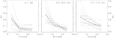
The polarization values as a function of the wavelength are plotted in Fig. 2. Although the integrated polarization degree and angle is highly affected by minor deviations in shift-and-add operations and PSF effects (see Sect. 4.2), the average values give a good overview of the circumstellar polarization distribution. The nebula emission in the outer annuli is polarized from 10% in K-band to 20% in J-band. This is in good agreement with a recent wide-field polarization study of the ONC in the NIR (Tamura et al., 2006).
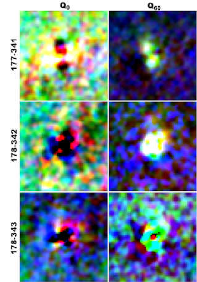
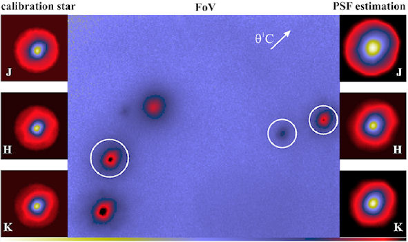
To remove all non-polarized light from the sources, we subtracted orthogonal components from each other. These images of the Stokes Q- or U-parameters show a characteristic trefoil pattern for most of the sources (Fig. 3). The trefoil is a mode in the AO wavefront reconstruction that may contain residual power if the AO-loop is run under variable atmospheric conditions. However, for the giant proplyd 177-341 we find significant butterfly patterns or two lobes, which is the polarization pattern expected for a circumstellar dust envelope.
The sources around 177-341 (Fig. 3) lie in a relatively dark region of the nebula. This is why we concentrate here in particular on the field of the proplyds around 177-341. The NIR-image in Figure 1 shows quite a different view of the proplyds morphology than the known optical images (Bally et al., 1998). First of all the bright ionization front, which covers inner structures of the proplyds in the optical is not visible in the NIR-images. This reveals, for example, a previously unknown source behind the tail of the proplyd 177-341 (Fig. 1, left). If the new source is a proplyd, it would be named 178-342, following the designation system introduced by O’Dell & Wen (1994). The observed JHK-colors differ from the neighbor 177-341, 178-342 seems redder (Table 1). This may be due to extinction by the overlying ionization front.
| Designation | R.A. | DECL. | Dist. to | IFa (opt.) | Magnitudeb | Color | |||
|---|---|---|---|---|---|---|---|---|---|
| (J2000) | (J2000) | Ori C | Tail | J | H | KS | J-H | H-K | |
| 157-323 | 05 35 15.71 | -05 23 22.59 | 11.25” | 0.7” | 9.88 | 9.05 | 8.93 | 0.83 | 0.11 |
| 158-323 | 05 35 15.82 | -05 23 22.50 | 9.75” | 1.8–2.5” | 9.73 | 8.83 | 8.53 | 0.91 | 0.3 |
| 158-326 | 05 35 15.83 | -05 23 25.62 | 10.2” | 0.85” | 12.9 | 11.34 | 10.65 | 1.56 | 0.69 |
| 158-327 | 05 35 15.79 | -05 23 26.61 | 10.53” | 1.0–1.5” | 11.68 | 10.4 | 9.66 | 1.28 | 0.75 |
| 163-317 | 05 35 16.27 | -05 23 16.72 | 6.42” | 1.6” | 10.14 | 9.41 | 9.2 | 0.72 | 0.21 |
| 166-316 | 05 35 16.60 | -05 23 16.32 | 7.36” | 0.4” | 11.4 | 10.47 | 10.2 | 0.93 | 0.27 |
| 167-317 | 05 35 16.73 | -05 23 16.63 | 7.08” | 0.67”2.1” | 10.37 | 9.41 | 8.94 | 0.96 | 0.47 |
| 177-341 | 05 35 17.67 | -05 23 40.96 | 25.98” | 0.8”3.5” | 12.44 | 11.83 | 11.53 | 0.61 | 0.3 |
| 178-342 | 05 35 17.76 | -05 23 42.50 | 27.2” | 12.93 | 11.67 | 11.2 | 1.26 | 0.46 | |
| 178-344 | 05 35 17.78 | -05 23 44.25 | 29.1” | 12.083 | 11.28 | 11.1 | 0.8 | 0.17 | |
| HD98161 | 11 17 12.01 | -38 00 51.72 | 6.075 | 6.019 | 5.992 | 0.056 | 0.027 | ||
-
a
Bally et al. (1998)
-
b
magnitude errors
| Designation | Filter | Aperture 0.1 ” | Annulus 0.3”-0.5” | Annulus 0.7”- 1.0” | |||||||||
|---|---|---|---|---|---|---|---|---|---|---|---|---|---|
| Pol.[%] | Ang.[∘] | Pol.[%] | Ang.[∘] | Pol.[%] | Ang.[∘] | ||||||||
| 157-323 | J | 18.11 | 0.70 | 35.5 | 1.0 | 14.38 | 0.25 | 45.5 | 0.3 | 14.89 | 0.37 | 38.7 | 0.8 |
| H | 4.76 | 0.26 | 84.4 | 5.0 | 6.41 | 1.96 | 22.7 | 0.2 | 11.95 | 0.68 | 26.0 | 1.0 | |
| KS | 3.71 | 1.91 | 62.1 | 4.7 | 2.77 | 0.64 | -67.2 | 29.6 | 11.25 | 0.71 | -56.7 | 0.9 | |
| 158-323 | J | 19.61 | 2.09 | 21.0 | 2.1 | 13.33 | 1.65 | 44.6 | 0.3 | 12.11 | 0.77 | 40.3 | 0.5 |
| H | 3.58 | 0.18 | 61.3 | 2.7 | 5.33 | 2.22 | 20.8 | 1.8 | 9.30 | 0.63 | 23.3 | 0.4 | |
| KS | 4.12 | 1.22 | 24.4 | 6.0 | 2.72 | 0.92 | -60.4 | 31.4 | 10.31 | 0.37 | -51.5 | 0.6 | |
| 158-326 | J | 45.32 | 4.52 | 35.9 | 2.1 | 32.53 | 0.71 | 29.9 | 0.7 | 46.87 | 1.53 | 29.4 | 0.1 |
| H | 9.12 | 2.50 | 89.2 | 1.6 | 9.26 | 1.31 | 29.9 | 0.6 | 20.06 | 0.74 | 29.1 | 0.1 | |
| KS | 3.08 | 1.17 | -76.4 | 10.5 | 2.61 | 0.46 | 42.2 | 7.4 | 4.30 | 0.61 | 17.6 | 2.0 | |
| 158-327 | J | 19.14 | 3.42 | 32.8 | 0.4 | 17.27 | 0.93 | 40.9 | 1.1 | 18.24 | 0.85 | 35.0 | 0.2 |
| H | 6.94 | 1.69 | -78.4 | 3.4 | 7.95 | 1.25 | 34.0 | 0.8 | 11.69 | 0.21 | 33.7 | 0.3 | |
| KS | 3.07 | 1.84 | -40.2 | 16.0 | 3.76 | 0.42 | 58.1 | 7.4 | 1.93 | 0.22 | -88.7 | 2.3 | |
| 163-317 | J | 24.77 | 2.72 | 34.9 | 1.5 | 9.92 | 0.44 | 59.5 | 2.9 | 13.23 | 1.65 | 71.0 | 0.3 |
| H | 2.89 | 1.66 | -29.5 | 23.1 | 6.41 | 1.91 | 68.3 | 4.3 | 12.57 | 0.87 | -87.3 | 0.3 | |
| KS | 3.96 | 1.61 | -79.1 | 5.5 | 5.10 | 0.98 | 29.9 | 1.0 | 3.12 | 0.43 | -24.8 | 21.0 | |
| 166-316 | J | 25.50 | 1.58 | 44.3 | 1.3 | 14.28 | 1.95 | 54.8 | 1.7 | 9.75 | 1.33 | 77.5 | 0.5 |
| H | 3.00 | 0.94 | 36.2 | 8.2 | 7.46 | 0.71 | 69.5 | 2.8 | 5.88 | 0.29 | 76.4 | 1.1 | |
| KS | 5.35 | 2.07 | -56.6 | 33.3 | 2.22 | 1.09 | 82.4 | 9.8 | 4.09 | 0.34 | -44.2 | 35.1 | |
| 167-317 | J | 23.94 | 1.38 | 30.8 | 1.7 | 11.70 | 1.25 | 38.5 | 1.0 | 15.28 | 2.48 | 11.9 | 2.3 |
| H | 5.86 | 1.48 | -10.8 | 1.5 | 7.84 | 2.30 | 56.8 | 3.0 | 13.34 | 6.57 | 21.4 | 6.4 | |
| KS | 1.14 | 0.75 | 85.6 | 11.5 | 5.09 | 0.45 | 68.4 | 2.9 | 8.26 | 6.54 | 19.1 | 9.6 | |
| 177-341 | J | 5.54 | 1.72 | -17.0 | 4.5 | 9.68 | 1.64 | -6.1 | 3.8 | 20.38 | 2.59 | -3.6 | 0.9 |
| H | 1.64 | 0.96 | 36.5 | 4.1 | 10.27 | 0.80 | 27.3 | 1.7 | 19.90 | 2.02 | 17.4 | 0.5 | |
| KS | 3.42 | 0.20 | 30.3 | 0.3 | 0.80 | 1.06 | -46.3 | 33.0 | 11.14 | 0.70 | -58.0 | 0.4 | |
| 178-342 | J | 17.12 | 3.77 | 50.7 | 0.6 | 20.48 | 2.03 | 15.4 | 1.6 | 25.18 | 2.87 | 7.5 | 0.2 |
| H | 6.30 | 2.07 | -41.3 | 35.5 | 11.02 | 3.93 | 16.2 | 4.8 | 23.94 | 1.99 | 6.4 | 0.6 | |
| KS | 11.11 | 3.19 | 63.5 | 4.4 | 0.36 | 1.14 | 87.5 | 30.6 | 3.14 | 1.08 | -48.2 | 34.2 | |
| 178-343 | J | 11.08 | 0.91 | 59.2 | 4.3 | 17.64 | 2.59 | 25.8 | 1.6 | 23.57 | 1.01 | 15.4 | 0.5 |
| H | 11.94 | 3.99 | -46.3 | 0.4 | 11.94 | 3.03 | 23.5 | 4.2 | 24.00 | 3.99 | 8.3 | 0.6 | |
| KS | 10.14 | 3.25 | 87.2 | 0.5 | 2.35 | 0.73 | -39.6 | 25.6 | 8.27 | 1.35 | -62.6 | 0.6 | |
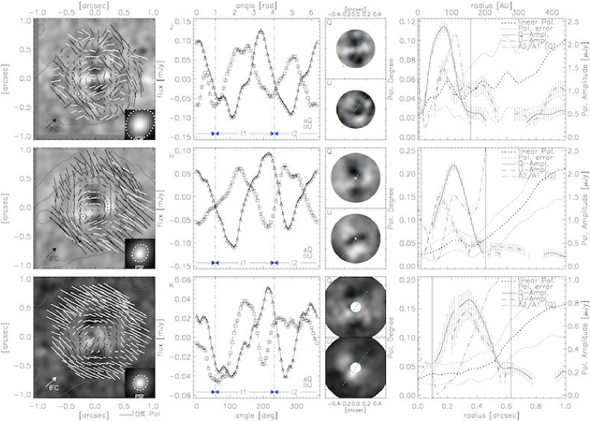
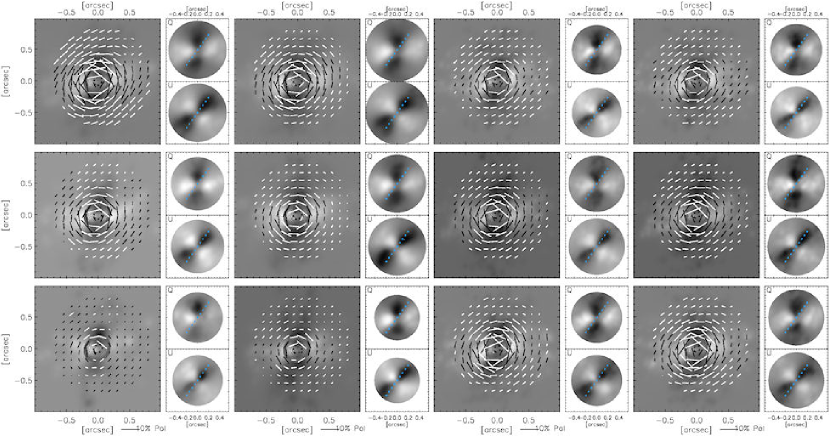
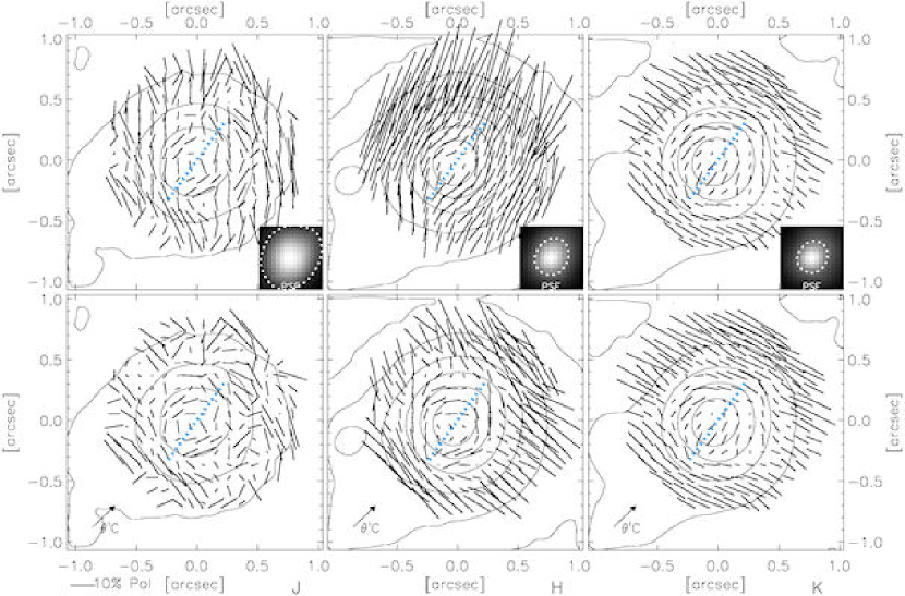
In Fig. 4 the polarization vectors patterns of 177-341 are shown. Close to the central source in the dust envelope, a centrosymmetric pattern is visible in relatively low polarization in the range of 5-10%. The reflection nebula in the outer regions of the proplyd shows a uniformly oriented polarization pattern with the same direction in all bands. This is almost perpendicular to the direction of Ori C, which is most likely the source of illumination of this part of the nebula.
4 Model and discussion
4.1 Polarization properties
Circumstellar accretion disks mark optically thick regions of the reflection nebula where the polarization patterns clearly depart from centrosymmetry. The vectors in these regions usually show low amplitudes of polarization of about 10% due to multiple scattering (Bastien & Menard, 1988). In the aperture of 0.35” for J-band to 0.5” for K-band, the centrosymmetric pattern is visible to the left in Fig. 4. A region of shortened and aligned vectors is not clearly resolvable in this view.
The outer regions show higher polarization and an aligned pattern from the illuminated reflection nebula from Ori C. The extent of the polarization pattern around 177-341 is determined in the radial plots to the right of Fig. 4 as follows. The fraction of polarized light as a function of the distance from the star shows a plateau of low polarization of the circumstellar envelope and is increasing for higher radii due to the nebula polarization. For a perfect centrosymmetry, the profiles along the position angle of the Q- and U-images should resemble a cosine. The amplitude of the cosine fitted to the Q- and U-profiles as a function of the distance then clearly defines the extent. The maximum radius increases from J- to K-band and a small plateau around the maximum extent is visible in all bands.
For a closer look at the spatial proportions, we examined the profile of the Q- and U-images by adding 5-degree bins over the determined radial range. These azimuthal Q-profiles show the characteristic cosine or W-curve for a dust envelope (Fig. 4, middle). In our data the profiles are not symmetric around zero as they should be, and this is equivalent to an offset in polarized flux and is related to effects of the PSFs. The long distance of about 26” from 177-341 to the AO guide star Ori C (Table 1) results in elongated PSFs for the observations (Cresci et al., 2005). The direction of elongation is towards Ori C (134∘ P.A.). A shifting of the profiles can be seen, after convolving simulated polarization images with the PSF of the observations (Figs. 13 and 14, only available electronically); therefore, the profiles of the convolved images of the data and simulations were shifted to be symmetric around zero so as to achieve a result closer to the actual centrosymmetric polarization pattern. This can be seen as a bootstrap calibration of the polarimetric images on the basis of the centrosymmetry of the envelope polarization. This has an impact on the pattern of the surrounding reflection nebula, which is highly polarized, but the total flux is low. The relative changes in the region of centrosymmetry are irrelevant due to the higher flux, while the analysis of the individual Q- and U-images in this study is not affected.
Since the Q- and U-images are not acquired simultaneously, there are deviations due to residual speckles and changes in seeing in addition to the elongated PSFs. These errors are emphasized during the determination of . As a consequence, no clear features are seen in the polarization degree images, and no direct comparison to convolved simulation images is possible. Hence, we tried to deconvolve the observational data in this case. For the PSF estimation the FOV with 177-341 was analyzed with the StarFinder program (Diolaiti et al., 2000). Three point-like sources around 177-341 were used to extract a field PSF (Fig. 15, only available electronically). For the deconvolution of the individual intensity images , the iterative Lucy-Richardson (Lucy, 1974) algorithm was chosen, which is known to be robust and stable even under difficult SNR conditions (Pruksch & Fleischmann, 1998). For the beam reconstruction, the deconvolved -images were convolved with a Gaussian of 0.25” FWHM, before the polarization degree images were generated. The diffraction limit at K-band is 0.15” for the 3.6m telescope, but under moderate seeing conditions and these low Strehl ratios of the observations (Sect. 2), an empirical limit for the achieved resolution is 1.5–2 diffraction limit units (Bonaccini et al., 1997). Without this smoothing, the deconvolved images are also dominated by high-frequency noise features enhanced progressively with the number of iterations (Lantéri et al., 1999). The algorithm converges fastest at the brightest source structures (Lucy, 1974). Therefore choosing too few iterations results in images of undefined resolution and quality. From our extensive experience with the algorithm (Ott et al., 1999), we chose iterations for the case of a single star dominating a single circumstellar structure.
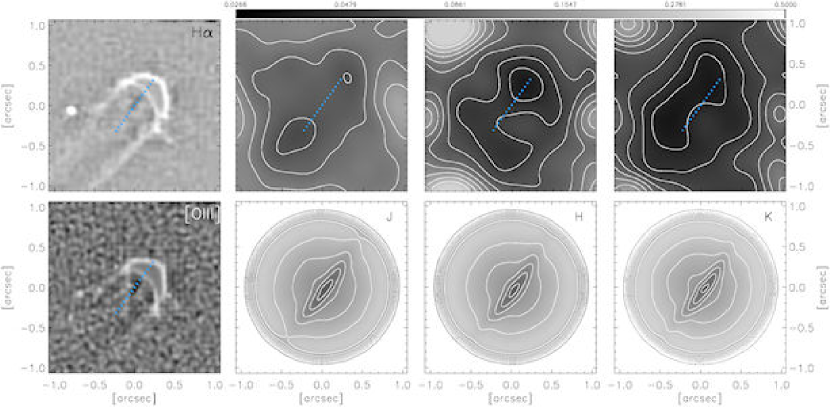
For the position angle of the disk, we compared the HST optical images and simulations to the polarization degree maps, obtained from deconvolved intensity images (Fig. 5). The parameters of the simulation are discussed in Sect. 4.2, but here a model with highly polarized envelope is shown to illustrate the disk signature in the envelope signal. In the optical images a small portion of the disk is seen in silhouette around the central star. Almost the same P.A. is found as an elongated region of low polarization in the NIR polarization images and can be quantified to . The diameter of the disk is about 300AU in this view. It must be stated that the direction of elongation of the PSFs differs only from the obtained P.A. and the elongated low polarization region could just be an artefact. But the extent of the region of 300AU clearly exceeds the PSF dimensions at least in the K-band. The P.A. is also confirmed by the following analysis.
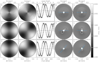
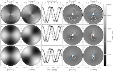
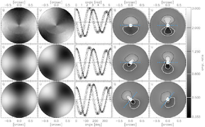
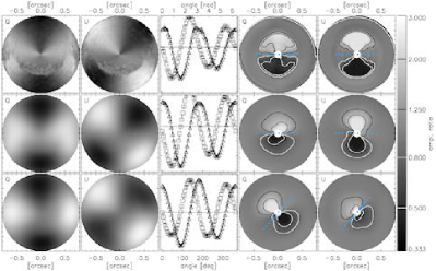
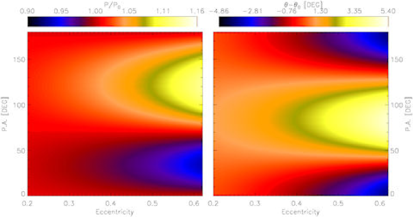
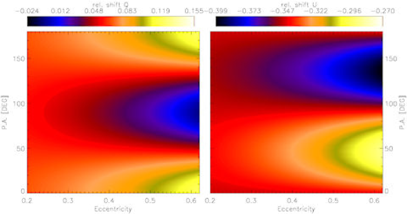
There is a noticeable modulation of the amplitudes of the profiles, which can constrain disk parameters if we consider the optically thick accretion disks. In regions where the disk lies in front of the illuminating source from the observer’s point of view the amplitude should be attenuated. The same applies where the disk blocks the propagation of the central light to outer regions of the envelope. This can be associated with the amplitude modulation (AM) technique used for communication and signal transmission. The envelope scattering is the carrier signal, i. e. a cosine with fixed phase in the Q- and U-profiles. Since there is no reference amplitude and we have only two cycle periods (see Fig. 4), only the ratio between the two can be determined as the modulation signal. To investigate these effects, we generated amplitude ratio maps, which are defined in polar coordinates as follows. For every position angle and radius (, ) the Q-profile over a range from ( ,) to (, ) is fitted with a function with free amplitude and amplitude offset , but fixed phase offset and , respectively. The best-fitting amplitude is divided by the one of the remaining (for clarification see Fig. 4, middle: dash-dotted lines). The cosine-fitting incorporates the model of the fixed carrier signal amplitude. The individual fitting over the radius allows arbitrary radial density and polarization profiles for the envelope, but rotational asymmetries like flattened envelopes are not considered. The result has an advantage over the pure Q-/U-profiles, since the attenuation of the signal is determined over the whole position angle, and the SNR is increased under the assumption of centrosymmetric envelope profiles. In principle the achievable spatial resolution is also enhanced by the high sensitivity of the signal to modulations. The results are shown in Figs. 6–8 for models with a flat and a flared disk, respectively. The behavior of the maps for the unconvolved images is as expected and can separate the disk signal from the envelope signal to some extent. A ratio map of a flat disk indicates the inclination angle. In this case the disk silhouette forms an ellipse with semi-major axis (the disk radius) and semi-minor axis , so the inclination is given by . Because the radial extent of the modulation in the amplitude ratio map refers to , the inclination can be determined. However, if the images are convolved with elongated PSFs, the Q- and U-maps perform differently, depending on the P.A. of the disk. For a P.A. of , the Q-map is distorted, because of the low amplitude of the carrier in the region of the modulation by the disk (Fig. 8, left panel, e.g.). The same applies for a P.A. of and the U-map. With a low-amplitude signal, PSF elongation effects become dominant.
|
|
|
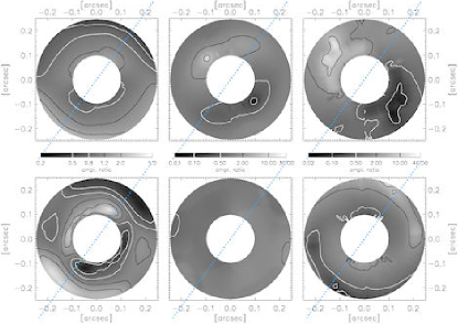
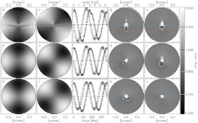
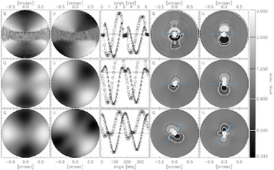
The maps of the amplitude ratio of the observations in J-, H-, and K-bands are shown in Fig. 9. In the Q-maps we find extremal ratios in the H- and K-band at a position angle of of the disk, so the Q-map should be less affected by elongation effects. The modulation in the U-maps is not significant – note the individual scaling of each band – and is interpreted as PSF- and noise effects. This is clear evidence that the disk is inclined and the portion in front of the star is located in the south west. Moreover, the radius of the minima can be determined precisely to 0.12” in the H-band and in K-band (Figs. 9 and 4 right, dash-dotted line). If a radius of and a flat disk are assumed, the shape of the ellipse is set and the minimum inclination angle is given by . Considering the height of the (flared) disk, this value is increased. This can be seen in Fig. 8, where the flared disk produces a greater extent as the flat disk for the same inclination. This results in an estimated possible inclination range of about 75∘–85∘, as the disk has to be inclined according to the signature in the ratio maps. The values of maximum ratios increase from the J- to the K-band. This can be interpreted as a stronger relative attenuation of the disk at higher wavelength. Since the polarization is lower in K-band, the total attenuation might be constant.
4.2 Modeling
There are two main processes for producing NIR/optical polarization: (i) scattering and (ii) differential absorption by non-spherical dust grains with the short axis primarily aligned along the local magnetic field, referred to as dichroic extinction (Bastien & Menard, 1988). In the case of a circumstellar envelope and disk, the first is relevant. To interpret the polarization data, we used a 3D radiation transfer code, based on the Monte Carlo method (Whitney & Hartmann, 1992, 1993). The model parameters of the presented simulations, which illustrate the signature of the disk in the polarization images (Figs. 5–9), are described in the following. In addition different models for grain size distributions and the impacts on the polarization images are discussed as an attempt to explain the increasing polarization pattern from the J- to the K-band.
The standard models for low-mass star formation include a slowly rotating, isothermal dense molecular cloud that collapses. The material with high angular momentum forms the circumstellar disk, while the one with lower angular momentum falls into the proto star. We adopted the model of an infalling proto-stellar cloud described by Terebey et al. (1984), often referred to as the TSC-model. Our configuration includes both a circumstellar envelope and a disk. We skipped a detailed modeling of bipolar cavities, since we do not see any clear evidence in the data. As mentioned in Whitney & Hartmann (1993), an infalling envelope can easily produce the specific polarization pattern of reflection nebulae, which are often interpreted as scattering from a disk. As a consequence we expect a highly inclined disk in the case of 177-341 as suggested by the optical images (Fig. 5), although we see a round, nearly centrosymmetric pattern in the polarimetric images. The critical parameter for reproducing the pattern is the mass infall rate in the TSC-model. As the envelope size is limited to about 300AU in our images (Fig. 4), the centrifugal radius is determined to 150AU in the model.
| MRN | KMH | KMHDC | |||||||||||||
|---|---|---|---|---|---|---|---|---|---|---|---|---|---|---|---|
| Band | |||||||||||||||
| J | 65 | 0.42 | 0.16 | 0.81 | 63 | 0.46 | 0.32 | 0.58 | 48 | 0.60 | 0.34 | 0.58 | |||
| H | 38 | 0.33 | 0.06 | 0.91 | 38 | 0.42 | 0.29 | 0.59 | 33 | 0.56 | 0.31 | 0.59 | |||
| K | 20 | 0.21 | 0.03 | 0.94 | 22 | 0.36 | 0.25 | 0.60 | 20 | 0.50 | 0.27 | 0.60 | |||
-
Note:
The unit of is [cm2g-1].
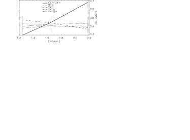
The dependency of polarization intensity on the wavelength refers to the effective grain size in the dust envelope, which scatter and polarize the emission from the central star (Elsasser & Staude, 1978). The polarization spectrum and peak polarization also depend strongly on the albedo , the opacity , and the asymmetry parameter of the grains. The latter defines the relation between forward scattering and isotropic scattering. For the grain size distribution and parameters, we adopted the models from Mathis et al. (1977), hereafter MRN and Kim et al. (1994), KMH. Table 3 gives an overview of the differences between the two commonly used models in the NIR (data from Kim et al. (1994) and Whitney et al. (1997)). In MRN, grain sizes are limited to , which is small compared to the wavelength of NIR-light, so the albedo and opacity drop for increasing wavelength. The KMH-model uses grain parameters obtained from fits to the interstellar extinction law. Local variations in the interstellar extinction curve are parameterized with the ratio of total to selective extinction . While the standard KMH deals with the diffuse interstellar medium (), the alternative (here denoted as KMHDC) is calculated for a dense cloud region with . Mathis & Wallenhorst (1981) stated that (i) an increasing implies an increasing size of particles, and (ii) , the wavelength of maximum polarization, is larger for regions with larger than the average . The peculiar extinction of Ori C is specified with . From the fit to the modified extinction curve in KMHDC, the distribution contains significantly fewer small- and intermediate-sized particles and a modest increase in larger sizes (Kim et al., 1994). This implies both a higher albedo and slightly greater and therefore an increased forward scattering. The extinction is less at short wavelengths and flattened towards higher wavelengths. We also tested a modified model with different grain properties only for the disks region. If grain growth in the disk is achieved, the scattering properties here should differ from the envelope. We adopted calculations from Pendleton et al. (1990) for large grains with a 4 times higher opacity and higher albedo, but also implemented a wavelength dependency, so that the scattering in K-band is increased. With high opacities and thus a high degree of multiple scattering, photons could be reprocessed by the disk more easily. Therefore more photons would be available in the outer regions of the envelope, so the scattering toward the observer could be enhanced.
The parameters for the envelope and the disk are chosen as determined from the data in the previous Section and listed in Table 4. This includes the envelope and disk size, and the inclination and P.A. of the disk. The mass infall rate for the envelope was probed in a wide range of – to vary the visible extent of the polarization pattern. A value of about gives the best results for the average radius of 0.48”. Such low infall rates would refer to a low-mass proto star in a transition between late Class I (embedded in envelopes) and Class II (with T Tauri disks) (Whitney et al., 2003).
| Parameter | Value |
|---|---|
| Number of photons | 10.000.000 |
| Stellar radius | 1.5 |
| Disk mass | 0.1 |
| Outer disk radius | 150AU |
| Inner disk radius | 4 |
| Inclination angle | |
| Position angle | |
| Scale height of disk | 0.001 |
| Inner envelope radius | 10 |
| Outer envelope radius | 150AU |
| Mass infall rate for envelope |
-
Note:
The spatial dimensions are derived from the observational data as described in Sect. 4.1.
The simulation images are convolved with the PSFs from the observational data to compare the results. The convolution with the elongated PSFs causes a change in the polarization properties: an offset of polarization of the position angle in the direction of the elongation is now visible (Fig. 13, only available electronically). This concurs with a shift in the Q- and U-profiles as seen in the centrosymmetric regions of the data (Fig. 4 and Sect. 4.1). The amount of offset depends on the specific model parameters, particularly the densities of disk and envelope and the disk inclination.
4.3 Discussion
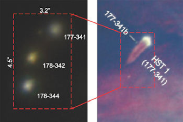
Henney & O’Dell (1999) derived an inclination angle of the disk of 177-341 of 75∘–85∘ by fitting photo-evaporation model data to emission line profiles of spectroscopic data. Robberto et al. (2002) modeled the SED for a photo-ionized proplyd and found that the disk emission is bright in the infrared and comparable to the central star. They also propose a highly inclined disk configuration for 177-341 by comparison to 10m-images. Bally et al. (2000) interpreted HST [O III]-images of 177-341 as a disk seen in silhouette against the bright IF. They propose a P.A. of , although the silhouette suggests a P.A. of about to because of the compact source about 0.5” east of this proplyd, which is likely to be an ultra compact Herbig-Haro object (177-341b in Fig. 1). Vicente & Alves (2005) performed a deep analysis on the HST data and determined the disk size from the IF diameter. For a distance of 0.01–0.3 pc to Ori C the FUV (far-ultraviolet) photons dominate the dissociation process and the disk radius is typically (Johnstone et al., 1998; Störzer & Hollenbach, 1999). In the case of 177-341 the diameter of the IF is 0.8” or 350 AU.
Considering these constraints on the disk and envelope configuration we find good agreement of the parameters with our polarimetric analysis. The compliant diameter and P.A. justify the deconvolution process and the introduced polarization amplitudes ratio maps. The inclination range obtained is also consistent with previous estimates. In the special case of a polarized envelope and a circumstellar disk, polarimetric differential images can be interpreted with this technique even under poor SNR and AO conditions. With the obtained values for the envelope size and the size, P.A. and inclination of the disk the simulations show similar polarization images.
According to a common model of the eroding disk mechanism (Bally, 2003), first the outer parts of the disk are being destroyed. One way for disks to survive the photo-evaporation by UV-radiation is for the dust grains to grow to sizes with radii cm. Evidence of grain growth in circumstellar disks in Orion has previously been found, because the outer portions of the giant disk of 114-426 contains grains m (Shuping et al., 2003). The efficiency of grain growth is predicted to be highest in the center of the disk where the highest densities and temperatures are found and photo-evaporation does not operate efficiently (Throop et al., 2001).
However our comparison of different dust models cannot explain the peculiar spectral polarization of 177-341. The models for dense clouds with high result in improved scattering at longer wavelengths, but do not reproduce the increasing polarization pattern extent from the J- to the K-band (Fig. 10). Also a simple model (KMH) of large grains in the disk shows only a moderate increase in the extent. As a conclusion, advanced modeling is required including significantly different dust properties. In particular the opacity distribution within the envelope might be worth a detailed investigation in future model improvements. Hughes et al. (2008) recently showed discrepancies between the extent of dust continuum emission and molecular gas emission, suggesting a different shape for the edge of the disk. An alternative disk model with a tapered edge agrees more with observations than the commonly used truncated power-law model.
5 Summary and conclusions
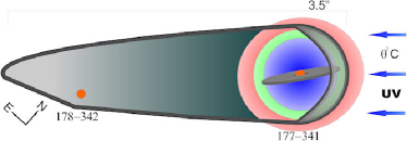
We have presented polarized emission maps of the circumstellar dust distribution of the giant proplyd 177-341 and found a complex morphology including both a circumstellar envelope and an accretion disk. The size of the disk was estimated with the diameter of the IF and confirmed in the polarization degree images. We extracted the inclination of the disk from a detailed study of the polarization profiles in the Stokes images. For the P.A. of the disk, we presented evidence of part of the disk seen in silhouette in the optical images, and we find matching position angles in the polarization amplitude ratio and in the deconvolved polarization-degree images due to multiple scattering in the disk. An overview of the results of the envelope and disk configuration is given in Fig. 11. The size of the dust envelope is obtained from the polarimetric differential images (Fig. 4) and increases from the J- (blue) to the K-band (red). In the H-band it is comparable to the diameter of the ionization fronts head in the optical (Fig. 1, right). 178-342 has no resolvable dust distribution, as the images in Fig. 3 show and modulates the shape of the IF of 177-341 in the optical (Fig. 1). The wavelength dependency of polarization intensity and the extent of the polarization pattern cannot be reproduced in the models by large grains in the circumstellar material. The comparison of common dust models shows evidence of the contribution of larger grain to polarization and scattering effects, but another mechanism must be present to explain the observational results.
We showed with our 4 m-class data that the technique of ground-based polarimetric differential imaging is suitable for mapping the dust emission very close to the central star (here about 0.1”). This is the case for the largest and brightest proplyds. Other proplyds close to the Trapezium might be worth observing with an 8 m-class telescope. The proplyds 158-326 and 166-316 are the most suited candidates, as these show extended emission and a modulated trefoil pattern in the polarimetric differential images. With the introduced PDI analysis techniques, we are able to constrain disk parameters, such as inclination, P.A., and size even when the disk structure itself is not resolvable.
Acknowledgements.
This work was supported in part by the Deutsche Forschungsgemeinschaft (DFG) via grant SFB 494.References
- Ageorges et al. (1997) Ageorges, N., Eckart, A., Monin, J.-L., & Menard, F. 1997, A&A, 326, 632
- Ageorges & Walsh (1999) Ageorges, N. & Walsh, J. R. 1999, A&AS, 138, 163
- Bally (2003) Bally, J. 2003, in ASP Conf. Ser. 287: Galactic Star Formation Across the Stellar Mass Spectrum, ed. J. M. De Buizer & N. S. van der Bliek, 263–274
- Bally et al. (2000) Bally, J., O’Dell, C. R., & McCaughrean, M. J. 2000, AJ, 119, 2919
- Bally et al. (1998) Bally, J., Sutherland, R. S., Devine, D., & Johnstone, D. 1998, AJ, 116, 293
- Bastien & Menard (1988) Bastien, P. & Menard, F. 1988, ApJ, 326, 334
- Bonaccini et al. (1997) Bonaccini, D., Prieto, E., Corporon, P., et al. 1997, in Presented at the Society of Photo-Optical Instrumentation Engineers (SPIE) Conference, Vol. 3126, Proc. SPIE Vol. 3126, Adaptive Optics and Applications, Robert K. Tyson and Robert Q. Fugate, Eds., p.589, ed. R. K. Tyson & R. Q. Fugate, 589–+
- Cresci et al. (2005) Cresci, G., Davies, R. I., Baker, A. J., & Lehnert, M. D. 2005, A&A, 438, 757
- Diolaiti et al. (2000) Diolaiti, E., Bendinelli, O., Bonaccini, D., et al. 2000, A&AS, 147, 335
- Eckart & Duhoux (1990) Eckart, A. & Duhoux, P. R. M. 1990, in ASP Conf. Ser. 14: Astrophysics with Infrared Arrays, ed. R. Elston, 336–+
- Elsasser & Staude (1978) Elsasser, H. & Staude, H. J. 1978, A&A, 70, L3+
- Hales et al. (2006) Hales, A. S., Gledhill, T. M., Barlow, M. J., & Lowe, K. T. E. 2006, MNRAS, 365, 1348
- Hashimoto et al. (2007) Hashimoto, J., Tamura, M., Suto, H., et al. 2007, PASJ, 59, 221
- Henney (2000) Henney, W. J. 2000, in Revista Mexicana de Astronomia y Astrofisica Conference Series, ed. S. J. Arthur, N. S. Brickhouse, & J. Franco, 198–200
- Henney & O’Dell (1999) Henney, W. J. & O’Dell, C. R. 1999, AJ, 118, 2350
- Hester & Desch (2005) Hester, J. J. & Desch, S. J. 2005, in ASP Conf. Ser. 341: Chondrites and the Protoplanetary Disk, ed. A. N. Krot, E. R. D. Scott, & B. Reipurth, 107–+
- Hillenbrand et al. (1998) Hillenbrand, L. A., Strom, S. E., Calvet, N., et al. 1998, AJ, 116, 1816
- Hughes et al. (2008) Hughes, A. M., Wilner, D. J., Qi, C., & Hogerheijde, M. R. 2008, accepted for publication in ApJ
- Jiang et al. (2005) Jiang, Z., Tamura, M., Fukagawa, M., et al. 2005, Nature, 437, 112
- Johnstone et al. (1998) Johnstone, D., Hollenbach, D., & Bally, J. 1998, ApJ, 499, 758
- Kim et al. (1994) Kim, S.-H., Martin, P. G., & Hendry, P. D. 1994, ApJ, 422, 164
- Kuhn et al. (2001) Kuhn, J. R., Potter, D., & Parise, B. 2001, ApJ, 553, L189
- Lada et al. (2000) Lada, C. J., Muench, A. A., Haisch, Jr., K. E., et al. 2000, AJ, 120, 3162
- Lada et al. (2004) Lada, C. J., Muench, A. A., Lada, E. A., & Alves, J. F. 2004, AJ, 128, 1254
- Lantéri et al. (1999) Lantéri, H., Soummer, R., & Aime, C. 1999, A&AS, 140, 235
- Lucy (1974) Lucy, L. B. 1974, AJ, 79, 745
- Mathis et al. (1977) Mathis, J. S., Rumpl, W., & Nordsieck, K. H. 1977, ApJ, 217, 425
- Mathis & Wallenhorst (1981) Mathis, J. S. & Wallenhorst, S. G. 1981, ApJ, 244, 483
- McCaughrean & Stauffer (1994) McCaughrean, M. J. & Stauffer, J. R. 1994, AJ, 108, 1382
- Meyer et al. (2006) Meyer, L., Eckart, A., Schödel, R., et al. 2006, A&A, 460, 15
- Monin et al. (2006) Monin, J.-L., Ménard, F., & Peretto, N. 2006, A&A, 446, 201
- O’Dell (2001) O’Dell, C. R. 2001, ARA&A, 39, 99
- O’Dell & Wen (1994) O’Dell, C. R. & Wen, Z. 1994, ApJ, 436, 194
- O’Dell et al. (1993) O’Dell, C. R., Wen, Z., & Hu, X. 1993, ApJ, 410, 696
- Olczak et al. (2006) Olczak, C., Pfalzner, S., & Spurzem, R. 2006, ApJ, 642, 1140
- Ott et al. (1999) Ott, T., Eckart, A., & Genzel, R. 1999, ApJ, 523, 248
- Pendleton et al. (1990) Pendleton, Y. J., Tielens, A. G. G. M., & Werner, M. W. 1990, ApJ, 349, 107
- Pruksch & Fleischmann (1998) Pruksch, M. & Fleischmann, F. 1998, in Astronomical Society of the Pacific Conference Series, Vol. 145, Astronomical Data Analysis Software and Systems VII, ed. R. Albrecht, R. N. Hook, & H. A. Bushouse, 496–+
- Robberto et al. (2002) Robberto, M., Beckwith, S. V. W., & Panagia, N. 2002, ApJ, 578, 897
- Shuping et al. (2003) Shuping, R. Y., Bally, J., Morris, M., & Throop, H. 2003, ApJ, 587, L109
- Shuping et al. (2006) Shuping, R. Y., Kassis, M., Morris, M., Smith, N., & Bally, J. 2006, ApJ, 644, L71
- Simpson et al. (2006) Simpson, J. P., Colgan, S. W. J., Erickson, E. F., Burton, M. G., & Schultz, A. S. B. 2006, ApJ, 642, 339
- Stauffer et al. (1994) Stauffer, J. R., Prosser, C. F., Hartmann, L., & McCaughrean, M. J. 1994, AJ, 108, 1375
- Störzer & Hollenbach (1999) Störzer, H. & Hollenbach, D. 1999, ApJ, 515, 669
- Tamura et al. (2006) Tamura, M., Kandori, R., Kusakabe, N., et al. 2006, ApJ, 649, L29
- Terebey et al. (1984) Terebey, S., Shu, F. H., & Cassen, P. 1984, ApJ, 286, 529
- Throop et al. (2001) Throop, H. B., Bally, J., Esposito, L. W., & McCaughrean, M. J. 2001, Science, 292, 1686
- Vicente & Alves (2005) Vicente, S. M. & Alves, J. 2005, A&A, 441, 195
- Whitney & Hartmann (1992) Whitney, B. A. & Hartmann, L. 1992, ApJ, 395, 529
- Whitney & Hartmann (1993) Whitney, B. A. & Hartmann, L. 1993, ApJ, 402, 605
- Whitney et al. (1997) Whitney, B. A., Kenyon, S. J., & Gomez, M. 1997, ApJ, 485, 703
- Whitney et al. (2003) Whitney, B. A., Wood, K., Bjorkman, J. E., & Cohen, M. 2003, ApJ, 598, 1079
12
13
14
15