Manipulating Spins by Cantilever Synchronized Frequency Modulation:
A Variable Resolution Magnetic Resonance Force Microscope
Abstract
We report a new spin manipulation protocol for periodically reversing the sample magnetization for Magnetic Resonance Force Microscopy. The protocol modulates the microwave excitation frequency synchronously with the position of the oscillating detection cantilever, thus allowing manipulation of the spin magnetization independent of both magnetic field gradient strength and cantilever response time. This allows continuous variation of the detected sample volume and is effective regardless of spin relaxation rate. This enhanced flexibility improves the utility of MRFM as a generally applicable imaging and characterization tool.
pacs:
76.90.+d, 07.57.Pt, 76.60.Pc, 76.30.-vMagnetic Resonance Force Microscopy (MRFM) is a ultra-sensitive technique for studying and imaging small numbers of spins s:rmp ; h:MagHandbook . Since the original proposal sidles91 ; s:prl , MRFM sensitivity has steadily improved to the single electron spin r:singlespin and the thousand nuclear spin level r:MaminStatisticalNMR ; r:90-nmresolutionimaging . Its superior spin sensitivity derives from large magnetic field gradients that couple the magnetic resonance signal to low noise, high quality factor mechanical cantilevers sr . Because MRFM has yet to be detected at the Larmor frequency, the force exerted by resonant spins on the cantilever must be modulated at the cantilever frequency (typically kHz). It is advantageous to have the signal detection bandwidth comparable to or greater than the inverse spin signal lifetime.
An approach to achieving the latter is to increase the cantilever response bandwidth through active -damping Bruland:jap96 ; r:wago98 ; r:microwireRFsource ; Meier:LowGammaNuclei . Although amplitude-based techniques have advantages Budakian:FastCantileverPhaseReversals , active -damping requires excellent cantilever displacement detection sensitivity Bruland:jap96 ; r:FeedbackCooling . Alternatively, cantilever frequency detection r:freqdetect:1991 such as implemented in the OSCAR (OScillating Cantilever driven Adiabatic Reversals) r:hundredspin protocol circumvents this problem. OSCAR cleverly exploits the large magnetic field gradient to manipulate the magnetization such that the resulting time-varying spin force on the cantilever is manifested as shift in its frequency—a signal detectable with a bandwidth limited only by noise considerations r:freqdetect:1991 . However, to effectively invert the spin magnetization, OSCAR requires field gradients of order T/m.
Here we introduce a new spin manipulation protocol based on frequency detection. As in OSCAR, our protocol is effective regardless of the cantilever response time. But, by frequency modulating the microwave frequency synchronously with the cantilever oscillation, we efficiently detect the MRFM signal regardless of the field gradient strength. This allows continuous adjustment of the spatial resolution length scale, inversely proportional to the field gradient, from coarse (requiring a low field gradient) to fine. This capability is important for the development of MRFM as a flexible and broadly applicable imaging and characterization tool. Frequency modulation excitation r:nmr has the additional advantage of minimizing spurious drive of the cantilever. Here we apply it to spins with slow relaxation time ), but it is also effective in the opposite limit h:oboukhov.dsp .
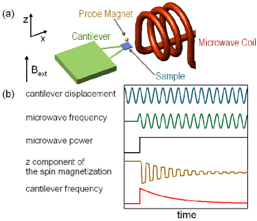
The experiment (see Fig. 1) was performed at K on the unpaired electron spins associated with E′ centers, silicon dangling bonds eaton:standardsample ; castle:eprimecenters (concentration /cm3) created in Clear Fused Quartz by 24.4 MRad 60Co -irradiation WilmadSiliconDioxideSample ; at 4.2 K s. The sample was glued on the end of a silicon nitride cantilever (spring constant N/m Veeco:SiNsoft ); this lowers the cantilever frequency to 1.63 kHz. The field gradient is generated by a diameter spherical NdFeB micromagnetic probe, and the microwave frequency is 5.96 GHz.
Mechanical detection of magnetic resonance requires periodic modulation of the force on the cantilever. For slowly relaxing spins (relaxation time ) the magnetic resonance technique known as adiabatic inversion is used to periodically invert the spins at the cantilever frequency h:MagHandbook . The effective magnetic field in the rotating frame slichter is given by
| (1) |
where is the gyromagnetic ratio, and are the frequency and magnitude of the transverse oscillating field, and and are the applied and micromagnetic probe fields respectively. If the effective field is rotated sufficiently slowly compared to , the spins follow the direction of the effective field by adiabatic fast passage slichter . MRFM experiments rely crucially on rotating spins through manipulation of .
Our spin manipulation protocol inverts through the second term on the RHS of Eq. (1), that is, by modulating the microwave frequency synchronously with the cantilever oscillation; we dub it CAntilever Synchronized frequency MOdulation (CASMO). As shown in figure 1(b), the cantilever, driven by a positive feedback circuit, oscillates continuously at its natural frequency, while the microwave frequency is modulated such that the spin magnetization oscillates in synchrony with the cantilever. The protocol is implemented through a digital signal processing programh:oboukhov.dsp .
Microwave irradiation, modulated so as to periodically invert the spin magnetization by means of cyclic adiabatic inversion, is initiated at an extremum of cantilever oscillation. This modulation is timed to ensure that the spin magnetization, and hence the force exerted on the cantilever due to the probe field gradient, is precisely in phase with the cantilever position : . As a consequence, this force is evident as an addition to the apparent cantilever compliance, where is the amplitude of the driven cantilever oscillation, and hence as a change in the cantilever frequency Berman:OSCAR . To thoroughly reverse the effective field, we need a large FM deviation . This is the limiting requirement that is traded for the relaxed field gradient requirement encountered in OSCAR.

It is essential to control the phase of the FM with respect to the cantilever oscillation correctly. The oscillatory force is phase synchronous with the FM, and the cantilever frequency only reflects the component of the force in phase with the cantilever oscillation. Fig. 2 shows the dependence of the CASMO generated signal on the phase difference between the FM and the cantilever oscillation. The MRFM signal is maximized when the phase difference is a multiple of , as expected. The slight offset results from a phase shift added by the bandpass filter applied to the cantilever displacement signal.
Fig. 3 shows the performance of the protocol with electron spin resonance signals obtained in field gradients varying by more than three orders of magnitude as probe-sample separation is decreased. Panel (a) shows the signal at a probe-cantilever separation of 150 m where T/m. The MRFM spectral width is determined by both the field inhomogeneity across the sample width and the inhomogeneity of the micromagnetic probe field. In this case, G; rather the spectral width is mainly due to the frequency modulation: G.
Fig. 3(b) shows the evolution of the MRFM signal with decreasing probe-sample separation. At smaller separations, signals occur at lower applied field because the probe field experienced by the sample is increasing. Plotted in the inset are the tip fields experienced by the resonating spins, estimated by subtracting the external field values at which the peak signals occur from the resonant field. They agree well with calculations of the field from a 44 m diameter uniformly magnetized NdFeB sphere. As the separation decreases, the widths of the spectra increase. Whilst the modulation deviation remains constant, increases a thousand-fold as decreases from m to m where T/m. At small separations the signal widths are dominated by the field inhomogeneity from the probe rather than the modulation deviation since . As shown in figure 3(c), the kG in this gradient.
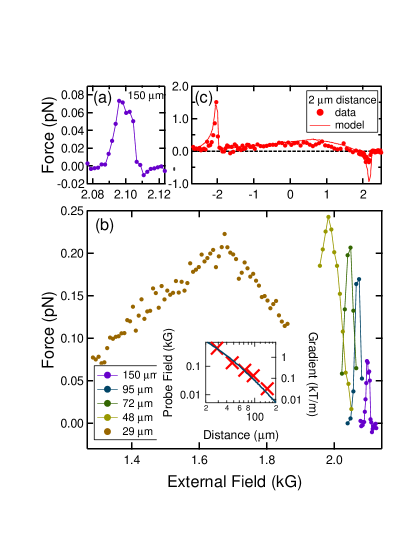
Despite the large increase in gradient, the maximum MRFM forces vary relatively weakly: from 0.07 to 0.3 pN throughout the range of separations. While the force per spin is proportional to the gradient, the number of resonating spins from an homogeneous sample is approximately inversely proportional to the gradient. So, to first order, the total force is independent of the gradient. Fig. 3(c) also shows our single fitting parameter modeling of the force spectrum at 2 m. The two prominent features near the resonance fields kG are the zero-probe-field resonances (ZPFR) arising from sample regions remote from the probe magnet where its field and gradient are small h:jmr02 . The spectra at , 29 and 48 m in Fig. 3(b) and (c) are one-dimensional spin-images zr:jap ; sv ; meier:mrfmlocalspc of our sample with varying spatial resolution (), all obtained using the CASMO protocol.
We have demonstrated a new protocol enabling spin-imaging with seamless variable resolution—from high to low field gradient—that avoids restrictions imposed by the cantilever response time. Frequency modulation manipulates resonant spins to generate a periodic force on the cantilever synchronized with its position. This force is evident as a cantilever frequency shift and hence can be detected with a bandwidth independent of cantilever response time. This phase control further allows phase-sensitive lock-in detection and hence atto-Newton force detection r:singlespin ; r:90-nmresolutionimaging . By expanding the range of measurement parameters open to MRFM measurement and enabling variable resolution spin-imaging, this moves MRFM closer to the goal of obtaining widely applicable imaging and characterization tool.
This work was supported by the Army Research Office through MURI grant W911NF-05-1-0414.
References
- (1) J. A. Sidles et al., Rev. Mod. Phys. 67, 249 (1995).
- (2) P. C. Hammel and D. V. Pelekhov, in Handbook of Magnetism and Advanced Magnetic Materials, edited by H. Kronmüller and S. Parkin (John Wiley & Sons, Ltd., New York, NY, 2007), Vol. 5.
- (3) J. A. Sidles, Appl. Phys. Lett. 58, 2854 (1991).
- (4) J. A. Sidles, Phys. Rev. Lett. 68, 1124 (1992).
- (5) D. Rugar, R. Budakian, H. J. Mamin, and B. W. Chui, Nature 430, 329 (2004).
- (6) H. J. Mamin, R. Budakian, B. W. Chui, and D. Rugar, Phys. Rev. B 72, 024413 (2005).
- (7) H. J. Mamin, M. Poggio, C. L. Degen, and D. Rugar, Nat. Nanotechnol. 2, 301 (2007).
- (8) J. A. Sidles and D. Rugar, Phys. Rev. Lett. 70, 3506 (1993).
- (9) K. J. Bruland, J. L. Garbini, W. M. Dougherty, and J. A. Sidles, J. Appl. Phys. 80, 1959 (1996).
- (10) K. Wago, D. Botkin, C. S. Yannoni, and D. Rugar, Phys. Rev. B 57, 1108 (1998).
- (11) M. Poggio et al., Appl. Phys. Lett. 90, 263111 (2007).
- (12) K. W. Eberhardt et al., Phys. Rev. B 75, 184430 (2007).
- (13) R. Budakian, H. J. Mamin, and D. Rugar, Appl. Phys. Lett. 89, 113113 (2006).
- (14) M. Poggio, C. L. Degen, H. J. Mamin, and D. Rugar, Phys. Rev. Lett. 99, 017201 (2007).
- (15) T. R. Albrecht, P. Grutter, D. Horne, and D. Rugar, J. Appl. Phys. 69, 668 (1991).
- (16) B. C. Stipe et al., Phys. Rev. Lett. 87, 277602 (2001).
- (17) D. Rugar et al., Science 264, 1560 (1994).
- (18) Y. Obukhov, K. C. Fong, D. Daughton, and P. C. Hammel, J. Appl. Phys. 101, 034315 (2007).
- (19) S. S. Eaton and G. R. Eaton, J. Magn. Reson. A 105, 354 (1993).
- (20) J. G. Castle, Jr., D. W. Feldman, P. G. Klemens, and R. A. Weeks, Phys. Rev. 130, 577 (1963).
- (21) Product number: WGSR-01-4, Wilmad LabGlass, N.J.
- (22) Model MLCT-NONM Type C from Veeco Probes.
- (23) C. P. Slichter, Principles of Magnetic Resonance (Springer-Verlag, New York, 1989).
- (24) G. P. Berman, D. I. Kamenev, and V. I. Tsifrinovich, Phys. Rev. A 66, 023405 (2002).
- (25) A. Suter, D. V. Pelekhov, M. L. Roukes, and P. C. Hammel, J. Magn. Reson. 154, 210 (2002).
- (26) O. Züger and D. Rugar, J. Appl. Phys. 75, 6211 (1994).
- (27) A. Schaff and W. S. Veeman, Appl. Phys. Lett. 70, 2598 (1997).
- (28) C. L. Degen et al., Phys. Rev. Lett. 94, 207601 (2005).