Cellular Systems with Full-Duplex Compress-and-Forward Relaying and Cooperative Base Stations
Abstract
In this paper the advantages provided by multicell processing of signals transmitted by mobile terminals (MTs) which are received via dedicated relay terminals (RTs) are studied. It is assumed that each RT is capable of full-duplex operation and receives the transmission of adjacent relay terminals. Focusing on intra-cell TDMA and non-fading channels, a simplified relay-aided uplink cellular model based on a model introduced by Wyner is considered. Assuming a nomadic application in which the RTs are oblivious to the MTs’ codebooks, a form of distributed compress-and-forward (CF) scheme with decoder side information is employed. The per-cell sum-rate of the CF scheme is derived and is given as a solution of a simple fixed point equation. This achievable rate reveals that the CF scheme is able to completely eliminate the inter-relay interference, and it approaches a “cut-set-like” upper bound for strong RTs transmission power. The CF rate is also shown to surpass the rate of an amplify-and-forward scheme via numerical calculations for a wide range of the system parameters.
I Introduction
Techniques for providing high data rate services and better coverage in cellular mobile communications are currently being investigated by many research groups. In this paper, we study the combination of two cooperation-based technologies that are promising candidates for achieving such goals, extending previous work in [1] - [4]. The first is relaying, whereby the signal transmitted by a mobile terminal (MT) is forwarded by a dedicated relay terminal (RT) to the intended base station (BS) [5]. The second technology of interest here is multicell processing (MCP), which allows the BSs to jointly decode the received signals, equivalently creating a distributed receiving antenna array [6]. The performance gain provided by this technology within a simplified cellular model was first studied in [7] , under the assumption that BSs are connected by an ideal backbone (see [8] for a survey on MCP).
Recently, the interplay between these two technologies has been investigated for amplify-and-forward (AF) and decode-and-forward (DF) protocols in [1][4] and [2][3], respectively. The basic framework employed in these works is the Wyner uplink cellular model introduced in [7]. According to the linear variant of this model, cells are arranged in a linear geometry and only adjacent cells interfere with each other. Moreover, inter-cell interference is described by a single parameter , which defines the gain experienced by signals travelling to interfered cells. Notwithstanding its simplicity, this model captures the essential structure of a cellular system and it provides insight into the system performance.
In this work we adopt a similar setup to the one presented in [4], in which dedicated full-duplex (FD) RTs are added to the basic linear Wyner uplink channel model and the signal path between adjacent RTs is considered (i.e., inter-relay interference). With coverage extension in mind, we focus on distant users having no direct connection to the BSs. Assuming a nomadic application in which the RTs are oblivious to the MTs’ codebooks, a form of distributed compress-and-forward (CF) scheme with decoder side information, similar to that of [11], is analyzed. It is noted that this scheme resembles the single-user multiple-relay CF scheme considered in [9, Thm. 3]. Focusing on a setup with infinitely large number of cells, the achievable per-cell sum-rate of the CF scheme is derived using the methods applied in [10]. The achievable rate, which is given as a solution of a simple fixed point equation, shows that the CF scheme completely eliminates the inter-relay interferences. Moreover the rate is shown to approach a “cut-set-like” upper bound for strong RTs transmission power. Finally, the performance of the CF scheme is compared numerically with the performance of an AF scheme, recently reported in [4], revealing the superiority of the CF scheme for a wide range of the system parameters.
II System Model
We consider the uplink of a cellular system with a dedicated RT for each transmitting MT. We focus on a scenario with no fading and adopt a circular version of the linear cellular uplink channel presented by Wyner [7]. RTs are added to the basic Wyner model following the analysis in [4] (see Fig. 1 for a schematic diagram of a single cell within the setup and its inter-cell interaction).
The system includes identical cells arranged on a circle, with a single MT active in each cell at a given time (intra-cell TDMA protocol), and a dedicated single RT to relay the signals from the MT to the BS (there is no direct connection between MTs and BSs). Accordingly, each RT receives the signals of the local MT, the two adjacent MTs, and the two adjacent RTs, with channel power gains , , and respectively. Likewise, each BS receives the signals of the local RT, and the two adjacent RTs, with channel power gains and respectively. The received signals at the RTs and BSs are affected by i.i.d. zero-mean complex Gaussian additive noise processes with powers and , respectively. It is assumed that the MTs use independent randomly generated complex Gaussian codebooks with zero-mean and power , whereas the RTs are subjected to an average transmit power constraint . The RTs are assumed to be oblivious of the MTs codebooks (nomadic application), and that no cooperation among MTs is allowed. In addition, the RTs are assumed to be capable of receiving and transmitting simultaneously (i.e., perfect echo-cancellation). It is noted that the propagation delays between the different nodes of the system are negligible with respect to the symbol duration. Finally, it is assumed that the BSs are connected to a central processor (CP) via an ideal backhaul network, and that the channel path gains and noise powers are known to the BSs, MTs, and CP.
III Preliminaries
III-A Wyner’s Model - Sum-Rate Capacities
Putting aside the inter-relay interference paths and the lack of joint MCP among the RTs, the mesh network of Fig. 1 is composed of two Wyner models (or two “Wyner lags”) [7]. The close relations of the current setup and the Wyner model renders the following definitions useful in the sequel.
The per-cell sum-rate capacity of the linear (or circular) Wyner uplink channel with infinitely large number of cells (), no user cooperation, optimal MCP, signal-to-noise ratio (SNR) , inter-cell interference factor (e.g. or in Fig. 1), and local path gain (e.g. or in Fig. 1), is given by [7]
| (1) |
where . When transmitter full cooperation is allowed the per-cell sum rate capacity of the above channel is achieved by “waterfilling” solution and is given by
| (2) | ||||
where .
III-B Upper Bound
Denoting and as the SNRs over the first “MT-RT” and second “RT-BS” lags, respectively, we have the following bound.
Proposition 1
The per-cell sum-rate of any scheme employed in the relay-aided Wyner circular uplink channel with infinite number of cells and no MT cooperation, is upper bounded by
| (3) |
Proof.
(outline) The rate expression is easily derived by considering two cut-sets, one separating the MTs from the RTs and the other separating the RTs from the BSs (or CP). We refer to this bound as “cut-set-like” bound since we also account for the assumption of no MTs cooperation in the first lag. ∎
It is noted that the upper bound continues to hold even if we allow multiple MTs to be simultaneously active in each cell (assuming a total-cell transmit power of ). Since both arguments of (3) increase with SNR it is easily verified that and that .
III-C Amplify-and-Forward Scheme
As a reference result, we consider the AF scheme with MCP analyzed in [4] for a similar infinite setup. For the AF scheme we make an additional assumption regarding the relaying delay, namely that the RTs amplify and forward the received signals with a delay of symbols (an integer). Interpreting the cellular uplink channel model with AF and MCP as a 2D linear time invariant system, and applying the 2D extension of Szegö’s theorem [7], the following result is derived in [4].
Proposition 2
An achievable per-cell sum-rate of AF relaying with optimal MCP and no spectral shaping, employed in the relay-aided infinite linear Wyner uplink channel, is given by
| (4) |
where
Furthermore, the optimal relay gain is the unique solution to the equation where
| (5) |
is the relay output power.
It is shown in [4] that the optimal gain is achieved when the relays use their full power , and that . In addition, is not interference limited and it is independent of the actual RT delay value .
IV Distributed Compress-and-Forward Scheme
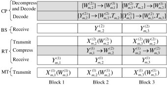
Here we describe the proposed CF-based transmission scheme, which organizes transmission into successive blocks (or codewords) of symbols, as sketched in Fig. 2. It should be remarked that transmission in the AF scheme presented in the previous section spans only one block (with some symbols margin due to the delay and the filter effective response time). For this reason, while in the AF scheme the RTs need to maintain only symbol synchronization, for the CF scheme to be discussed below, block synchronization is also necessary.
With denoting the association to the first “MT-RT” and second “RT-BS” lags, respectively, the received signal at the th RT in an arbitrary symbol of the th block is
| (6) |
where , are the signals transmitted by the MTs (to be defined in the sequel), denotes the additive noise at the RT, and the inter-relay interference is
| (7) |
The received signal at the th BS is
| (8) |
where are the signals transmitted by the RTs, and denotes the additive noise at the BS.
The proposed CF scheme works as follows (see Fig. 2 where shadowed boxes indicate zero time processing). The
basic idea is to have the RTs compress the signal
received in any th block (say in Fig. 2) and forward it in the th block (e.g., via
a channel codeword , by exploiting the side
information available at the CP about the compressed signals
. In fact, with the proposed scheme, in the th
block, the CP decodes the channel codewords
transmitted by the RTs, and these are correlated with the signal
(6) via
(7). Based on this side
information, distributed CF is implemented at the RTs according to
[11] via standard vector quantization and binning.
A more formal description of the CF scheme is presented
below.
Code Construction: 1) At the MTs:
each th MT generates a rate- Gaussian random channel
codebook according to (no optimality is claimed);
2) At the RTs: 2.a) Each RT generates a rate- Gaussian random channel codebook
according to ;
2.b) Each RT generates a rate- Gaussian quantization codebook
according to the marginal
distribution induced by
| (9) |
where the quantization noises are i.i.d.
zero-mean complex Gaussian independent of all other random
variables (no optimality is claimed). Each quantization codebook
is randomly partitioned into bins, each of size
;
Encoding at the MTs: each MT sends its message
by
transmitting the symbol vector over the first
“MT-RT” lag;
Processing at the
RTs: 1) Compressing: each RT employs vector quantization
using standard joint typicality arguments via the quantization
codebok , to compress the
previously received vector into with the corresponding bin index ; 2) Encoding: each RT sends its bin index
by transmitting over the second
“RT-BS” lag;
Decoding at the CP:
1) Decoding the bin indices: the CP collects the received
signal vectors
(where ) from all the BSs through the backhaul
links. Then it decodes the resulting multiple-access channel (MAC)
using standard methods (e.g., [12]) to recover
an estimate ; 2)
Composing the side information: the CP uses the decoded bin
indices to compose the
side information vectors , where
, to be used in the
next block; 3) Decoding the MTs messages: The CP
uses the previous side information
and looks for a unique
joint typical triplet within the bins indicated by , according to the joint distribution induced by
(6), to recover .
V Sum-Rate Analysis
Here we derive the per-cell sum-rate (or symmetric rate) achievable via the proposed CF scheme.
Proposition 3
An achievable per-cell sum-rate of the CF scheme employed in the relay-aided Wyner circular uplink channel with infinite number of cells , is given by
| (10) |
where is the unique solution to the following fixed point equation
| (11) |
Proof.
(outline) See Appendix -A. ∎
It is concluded that the rate is independent of the inter-relay interference. Moreover, the CF scheme performs as if there are no inter-relay interferences (i.e. ) and its rate coincides with the results of [10] interpreting the second “RT-BS” lag as the backhaul network with limited capacity . Also note, that the result holds even if we relax the RT perfect echo-cancellation assumption as long as the CP is aware of the residual echo power gain.
Since is given in an implicit integral form (1), we can not solve the fixed point equation (11) analytically. Nevertheless, since is monotonic in , (11) is easily solved numerically. It is also evident that the CF rate increases with the relay power . Hence, as with the AF scheme full relay power usage is optimal.
It is easily verified that when then , and does not achieve the upper bound (3). This is since . On the other extreme when then , and achieves the upper bound . In the next section, numerical results reveal that the CF scheme outperforms the AF scheme over a wide range of the system parameters.
VI Numerical Results
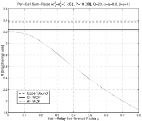
In Fig. 3 the per-cell sum-rates of the CF and AF schemes are plotted along with the upper bound (3), as functions of the inter-relay interference factor for [dB], [dB], , , and . It is noted that the AF curve is plotted with optimal relay gain (resulting in a full usage of the relay power ). Examining the figure, the benefits of the CF scheme are evident in view of the deleterious effect of increasing inter-relay interference on the AF rate; the CF scheme provides almost twice the bits per channel use than the AF rate, for strong inter-relay interference levels. Also visible from the figure is the proximity of the CF rate to the upper bound (less than 0.2 bits per channel use) which for this setting is dominated by the rate of the first “MT-RT” lag.
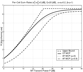
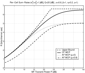
Figures 4 and 5 present the CF and AF rate curves and the upper-bound as functions of the MTs power , for [dB], , and . Here, we focus on two scenarios: (a) a setting with symmetrical first and second lags, i.e. , and (b) a setting with asymmetrical lags, i.e. . In both figures we include the AF rate curves for the two extremes and , which represent weak and strong inter-relay interference scenarios, respectively. It is noted that any AF rate curve with is confined between these two curves. Examining the figures it is observed that the CF performs well (within one bit per channel use of the upper bound) in both scenarios over the entire displayed range of MTs power . On the other hand, the AF scheme performs well in both scenarios only for low inter-relay interference levels and low MTs power . Other results (not presented here) show that the AF scheme is slightly beneficial over the CF scheme under certain conditions (e.g., high , and asymmetrical lags ).
VII Concluding Remarks
In this work we have considered a simplified two-hop cellular setup with FD relays and inter-relay interference. Focusing on nomadic application, a form of distributed CF with decoder side information scheme, has been analyzed. We have derived the achievable per-cell sum-rate for an infinitely large number of cells, and have shown that the CF scheme totally eliminates the inter-relay interference. Numerical results reveal that the CF rate curves are rather close to a “cut-set-like” upper bound, and also demonstrate the superiority of the proposed CF scheme over the MCP AF scheme of [4], for a wide range of the system parameters.
-A Proof of Proposition 2 (Outline)
We focus on the decoding stage at the CP for the th block (recall Fig. 2). Since the rate of the channel codebooks used by the RTs on the second lag is equal to the per-cell capacity of the corresponding Wyner channel (see Sec. III-A), the CP is able to correctly decode from the previous block and from the current with high probability. Based on the former, it can also build an accurate estimate As per Fig. 2, the CP then attempts to decode the messages In the following, the variables of interest are , and which are denoted for simplicity as , and To elaborate, we note that, due to the quantization rule (9), the following Markov relation holds Recall also that the CP decodes by looking for jointly typical sequences where belong to the MTs codebooks (each of size ) and are within the bins (of size ) whose indices are given by .
Assuming , for large block length , the probability of error is dominated by the events where a set with erroneous and , for any subsets , is found that is jointly typical in the sense explained above (see [10]). Using the union bound, we found that the error probability is bounded
It follows that, in order to drive the probability of error to zero, it is sufficient that
| (12) | ||||
Now, defining and , and using the Markov properties of the compression scheme, we have that
| (13) | ||||
and
| (14) | ||||
and it is also easy to prove that
| (15) |
Acknowledgment
The research was supported by a Marie Curie Outgoing International Fellowship and the NEWCOM++ network of excellence both within the 6th and 7th European Community Framework Programmes, by the U.S. National Science Foundation under Grants ANI-03-38807 and CNS-06-25637, and the REMON consortium for wireless communication.
References
- [1] O. Simeone, O. Somekh, Y. Bar-Ness, and U. Spagnolini, “Uplink throughput of TDMA cellular systems with multicell processing and amplify-and-forward cooperation between mobiles,” IEEE Trans. Wireless Commun., pp. 2942–2951, Aug. 2007.
- [2] O. Simeone, O. Somekh, Y. Bar-Ness, and U. Spagnolini, “Throughput of low-power cellular systems with collaborative base stations and relaying,” IEEE Trans. on Inform. Theory, vol. 54, pp. 459-467, Jan. 2008.
- [3] O. Simeone, O. Somekh, Y. Bar-Ness, H. V. Poor, and S. Shamai (Shitz), “Capacity of linear two-hop mesh networks with rate splitting, decode-and-forward relaying and cooperation,” in Proc. of the 45th Annual Allerton Conference on Communication, Control and Computing, (Monticello, IL), Sep. 26–28 2007.
- [4] O. Somekh, O. Simeone, H. V. Poor, and S. Shamai (Shitz), “Cellular systems with full-duplex amplify-and-forward relaying and cooperative base-stations,” in Proc. of the IEEE Intl. Symp. on Inform. Theory (ISIT), (Nice, France), pp. 16–20, Jun. 2007.
- [5] Y.-D. J. Lin and Y.-C. Hsu, “Multihop cellular: A new architecture for wireless communications,” in Proc. of the IEEE INFOCOM (3), (Tel-Aviv, Israel), pp. 1273–1282, Mar. 26–30, 2000.
- [6] S. Zhou, M. Zhao, X. Xu, and Y. Yao, “Distributed wireless communication system: a new architecture for public wireless access,” IEEE Commun. Magazine, pp. 108–113, Mar. 2003.
- [7] A. D. Wyner, “Shannon-theoretic approach to a Gaussian cellular multiple-access channel,” IEEE Trans. on Inform. Theory, vol. 40, pp. 1713–1727, Nov. 1994.
- [8] O. Somekh, O. Simeone, Y. Bar-Ness, A. M. Haimovich, U. Spagnolini, and S. Shamai (Shitz), Distributed Antenna Systems: Open Architecture for Future Wireless Communications, ch. An Information Theoretic View of Distributed Antenna Processing in Cellular Systems. Auerbach Publications, CRC Press, May 2007.
- [9] G. Kramer, M. Gastpar, and P. Gupta, “Cooperative strategies and capacity theorems for relay networks,” IEEE Trans. on Inform. Theory, vol. 51, pp. 3037– 3063, Sep. 2005.
- [10] A. Sanderovich, O. Somekh, and S. Shamai (Shitz), “Uplink macro diversity with limited backhaul capacity,” in Proc. of the IEEE Intl. Symp. on Inform. Theory (ISIT), (Nice, France), pp. 11–15, Jun. 2007.
- [11] M. Gastpar, “The Wyner -Ziv problem with multiple sources,” IEEE Trans. on Inform. Theory, vol. 50, pp. 2762–2768, Nov. 2004.
- [12] T. M. Cover and J. A. Thomas, Elements of Information Theory. John Wiley and Sons, Inc., 1991.