Coinage-metal capping effects on the spin-reorientation transitions of Co/Ru(0001)
Abstract
Thin films of Co/Ru(0001) are known to exhibit an unusual spin reorientation transition (SRT) coupled to the completion of Co atomic layers for Co thicknesses under 4 layers. By means of spin-polarized low-energy electron microscopy, we follow in real space the magnetization orientation during the growth of atomically thick capping layers on Co/Ru(0001). Capping with coinage-metal (Cu, Ag, Au) elements modifies the SRT depending on the Co and overlayer thickness and on the overlayer material, resulting in an expanded range of structures with high perpendicular magnetic anisotropy. The origin of the SRT can be explained in terms of ab-initio calculations of the layer-resolved contributions to the magnetic anisotropy energy. Besides the changes in the SRT introduced by the capping, a quantitative enhancement of the magnetic anisotropy is identified. A detailed analysis of the interplay between strain and purely electronic effects allows us to identify the conditions that lead to a high perpendicular magnetic anisotropy in thin hcp Co films.
1 Introduction
The magnetism of ultra-thin films is a fascinating field with important device applications[1]. One remarkable effect is the film-thickness dependence of the magnetic anisotropy (MA), and particularly the possibility of perpendicular magnetic anisotropy (PMA) in films that are a few monolayers (ML) thick[2]. The magnetic anisotropy energy (MAE) responsible for this effect arises from a delicate balance between competing contributions[3, 4], including the influence of strain in the films, as well as interactions with the substrate. Often there is a single transition from perpendicular orientation of the magnetic easy axis to an in-plane orientation as the magnetic film thickness is increased. This is due to the increasing weight of the long-range dipolar magnetostatic energy, which is reduced for in-plane orientation of the magnetization. More unusual is the presence of successive easy-axis reorientation transitions in thin films[5, 6]. In some thin film systems, the easy-axis is in-plane up to a critical thickness, then it turns to a perpendicular orientation, and back again to in-plane orientation at a larger thickness, i.e. they show a double spin reorientation transition (SRT). This is attributed to a complex interplay of magnetic interactions influenced by atomic structure and electronic effects. For a few systems, in particular Fe/W(110)[7] and Co/Ru(0001)[8], it has been shown that the SRTs take place abruptly at consecutive atomic layers. These experimental observations can be understood by means of ab-initio calculations that take into account epitaxial strain as well as changes in the electronic structure of the magnetic material that are induced by the presence of adjacent media (vacuum or substrate)[8].
For a number of reasons, it is interesting to study the effects of capping the films with more inert, non-magnetic materials such as gold, silver, or copper. Besides the possibility of improving the environmental stability of magnetic transition metal films, many cases have been observed where the addition of ultrathin layers of a non-magnetic material can have important effects on the magnetic properties, and in particular on the MA. Large PMA has been obtained for a wide variety of Co films and multilayers formed in combination with non-magnetic layers of Pd, Pt or Au[9, 10, 11, 12, 13]. In Co/Cu(100) films, the deposition of minute amounts of copper [14] can rotate within the plane the weak in-plane anisotropy of the cobalt films. In Co/W(110) films, the addition of a Cu cap produces an increase in the PMA at a Cu thickness close to one monolayer[15]. Even adsorption of gases influences the MAE, as evident from the SRT induced upon coverage of Co/Pt(111) films with CO [16] and from the inverse SRT found in Fe/W [17].
Coinage-metal capping thus provides an interesting lever to control the MA of ultrathin films. The key mechanisms that underlie the magnetic effects induced by non-magnetic layers include crystalline structure, strain, and electronic hybridization. First, different crystal structures of the magnetic film and the overlayer constitute a source of strain, and they may influence the symmetry of the lattice through changes of the stacking sequence. This may alter the MAE [18, 19, 20], as we will discuss in detail in a forthcoming publication [21]. In addition, hybridization at the interface alters the distribution of electronic levels and subsequently the magnetic properties of both the magnetic film and the polarized cap material, with a direct impact on the MAE.
Some Co-based thin film systems, such as those including Cu, Au and Pt[22, 23, 24, 20, 25], have received more attention in the literature than Co/Ru [26, 27, 28, 29, 26, 30]. Nonetheless, Co/Ru is a particularly interesting prototypical system. Both substrate and film material share the same hcp crystal structure, and the Ru lattice parameter is closer to Co than those of Au or Pt. Furthermore this system has a peculiar double spin-reorientation transition, linked to the completion of atomic layers, as we showed in a previous paper[8]. Building on the earlier observations on bare Co/Ru films, we report here the changes induced in the easy-axis of magnetization of Co/Ru(0001) films of different thicknesses as a function of coinage-metal overlayer material and thickness. Our results are based on measurements using spin-polarized low-energy electron microscopy (SPLEEM) and on fully relativistic ab-initio calculations within the screened Korringa-Kohn-Rostoker (SKKR) method. We find that coinage-metal capping of Co/Ru films results in SRTs that depend strongly on chemical nature as well as atomic layer thickness of the capping layers. A summary of our measurements is shown in table 1. One important difference between capped Co/Ru films, compared to the case of bare Co/Ru films, is that the range of Co film thicknesses for which PMA occurs is broadened, especially for the case of Au caps. In addition, even when the capping layer does not induce changes in the easy-axis of the magnetization of the Co film, the Curie temperature may change. The complicated interplay of effects leading to these results is studied by means of calculations of the MAE which allow to separate the different contributions (strain, hybridization, thickness) in a layer-resolved analysis. In this way we determine the factors that lead to high PMA in thin hcp Co films.
| Capping material | ||||||||
|---|---|---|---|---|---|---|---|---|
| Bare | Ag | Cu | Au | |||||
| Co thickness | 1 ML | 2 ML | 1 ML | 2 ML | 1 ML | 2 ML | 3 ML | |
| 2 ML | PMA | PMA | PMA | PMA | PMA | PMA | PMA | PMA |
| 3 ML | in-plane | PMA | in-plane | PMA | in-plane | PMA | PMA | PMA |
| 4 ML | in-plane | in-plane | in-plane | PMA | in-plane | PMA | PMA | PMA |
| 5 ML | in-plane | in-plane | in-plane | in-plane | in-plane | PMA | PMA | in-plane |
| 6 ML | in-plane | in-plane | in-plane | in-plane | in-plane | PMA | PMA | in-plane |
2 Experimental details
The experiments were carried out in-situ in two different ultrahigh vacuum low-energy electron microscopes (LEEM). The first one is a conventional LEEM[31] equipped for local-area diffraction studies. The second instrument is equipped with a spin-polarized electron gun (SPLEEM[32]), which provides magnetic contrast. Both instruments have facilities for in-situ heating (up to 2300 K) and cooling (down to 100 K) the samples while recording images at up to video rate.
The Co films were grown on two different Ru(0001) crystals, one in each experimental chamber. Both Ru substrates were cleaned in-situ by repeated cycles of exposure to oxygen followed by heating to 1800 K. Both Ru substrates contained flat regions at least 100 m wide with mono-atomic steps separated by more than 5 m. The metal films (Co, Cu, Ag, Au) were grown by physical vapor deposition from calibrated, electron-beam heated evaporators. The Co doser was charged with a bare Co rod, while in the other dosers charges were held in Mo-crucibles. Typical deposition rates are 0.1-1 ML/min.
During Co growth the ruthenium crystals were heated up to between 425 K and 520 K, and the pressure remained below 4 torr. The growth was monitored in real time by LEEM. On large step-free terraces, we find that Co grows in a nearly perfect layer-by-layer mode for at least the first 8 ML. To achieve this type of growth, it is important to avoid substrate regions with high step density, which tend to enhance three-dimensional growth in Co/Ru(0001) in particular[33], and in strained systems in general[34].
The deposition of Cu, Ag, Au capping layers was done at 513 K, 490 K, and 440 K, respectively. The development of preparation schedules that result in atomically perfect regions of coinage-metal capping overlayers on top of atomically perfect regions of Co/Ru(0001) films again takes advantage of in-situ sample growth during SPLEEM observation. It turns out that it is possible to grow the capping layers at relatively high temperature, promoting step-flow growth (or the formation of conveniently large islands). At least in the case of thicker, more bulk-like Co films, the possibility to prepare atomically sharp interfaces and capping layers with homogeneous thickness benefits from the fact that coinage metals are immiscible with Co in the bulk[35] and that coinage metals have a lower surface energy than Co[36, 37]. Preventing alloying is more challenging in the limit of monolayer-thick films of Co on Ru. These films are severely strained and lattice matched to the substrate[33], and alloying has been observed in the first layer of AgCo on Ru(0001), where the chemical energy cost of putting Ag and Co atoms in contact is overcome by the elastic energy gain from the matching of the AgCo combination to the Ru substrate lattice spacing[38, 39]. Consequently, we have only grown Ag and Au capping layers on Co films thick enough to be fully relaxed (at least 2 ML thick), and we did not attempt to prepare Ag or Au caps on top of single-monolayer Co films. In case of Cu capping layers, this type of elastic energy gain upon alloying is not expected, because Cu is nearly lattice matched to the relaxed Co films (mismatch is 1.5%). Although surface-alloying of Co and Cu has been observed in monolayer films on Ru[40] and may be unavoidable, we did explore the effects of preparing Cu caps on all the Co films, including on unrelaxed Co monolayer films. In case of monolayer-thick Co films capped by a single layer of Cu, we were unable to detect a magnetic signal, indicating that these structures are either not ferromagnetic, or have a Curie temperature below 100 K (that temperature is the lower limit of our experimental setup).
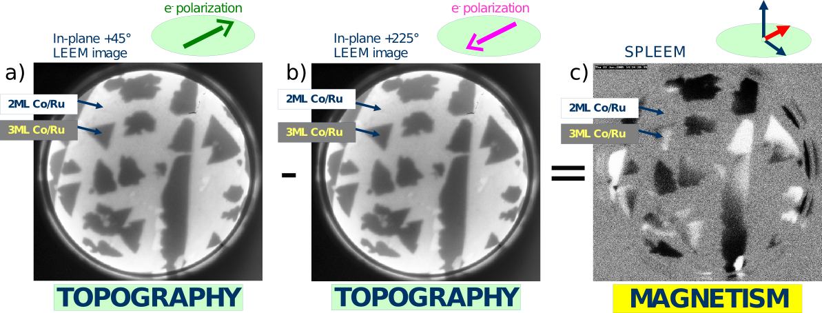
SPLEEM[32] was used to monitor the easy axis of magnetization of the films. For a spin-polarized low-energy electron beam, the reflectivity of the sample surface depends not only on topography, chemical composition, and other factors, but also on the relative alignment between the beam polarization and the sample magnetization. The SPLEEM is equipped to allow the spin direction of the electron beam to be changed to any desired orientation[41]. By acquiring pairs of images taken with reversed spin-polarizations (Fig. 1), we can employ pixel-by-pixel subtraction of the two images to enhance magnetic contrast while suppressing all other forms of contrast (topography etc.). In the resulting SPLEEM images, bright (dark) contrast indicates that magnetization has a component parallel (antiparallel) to the spin-up direction of the electron beam. By collecting three such pairs of images, using three orthogonal quantization axes (usually the direction perpendicular to the surface plus two orthogonal in-plane directions), we can obtain triplets of SPLEEM images that reflect the 3-dimensional (3D) components of the magnetization vector in the sample surface [42].
3 Theoretical method
Calculations have been performed within a fully relativistic ab-initio framework based on density functional theory using the SKKR (Screened Korringa-Kohn-Rostoker) method. The main features of this approach are described elsewhere [43]. Here we only mention those relevant for the present study. Within the SKKR formalism, the structure under study is described as a stack of layers with a common two-dimensional (2D) lattice parameter. Consequently, the method naturally provides the layer-resolved physical quantities. To determine the uniaxial magnetic anisotropy of a specific structure, we first perform a self-consistent calculation to obtain the electronic potentials and exchange fields, and then, applying the force theorem, we calculate the band energy term for two orientations of the magnetization, normal and parallel to the surface. Convergence is achieved using an energy-dependent k-point mesh that includes as many as points in the irreducible Brillouin zone, so that the accuracy in the final MAE values is 0.001 meV. The MAE is defined as the balance between the band and dipole energy contributions:
| (1) |
with
| (2) |
defined as the difference between energies obtained with the magnetization vector () contained in the surface plane or directed along the normal to the surface. Within this convention, a positive MAE corresponds to an easy-axis of magnetization along the normal to the surface. The dipole energy for a particular orientation of is obtained from the classical interaction between magnetic dipoles in atomic Rydberg units:
| (3) |
where is the magnetic moment at site and the sum is restricted to ; being a demagnetization energy, it always favors in-plane magnetization.
The structures we have modelled are thin Co films 2-10 ML thick on a Ru(0001) substrate, either bare or covered by a coinage-metal capping of 1 to 10 ML thickness. To understand specific effects, other capping metals such as Ru or Pt have also been considered. As shown in table 2, there are significant structural differences between the elements forming these structures. In our calculations, we use a common 2D lattice parameter (a2D) for all layers of a given structure. In most cases, we use the intermediate value corresponding to the Ru(0001) lattice, but we also analyze the effect of different values of a2D on the main results. In order to recover the atomic volume corresponding to each element, interlayer relaxations (d) were allowed. The results presented here correspond to d values of -6 % for the Co and Cu layers, and +6 % for Au, Ag and Pt, both with respect to the Ru interlayer distance. At the metal/Co interfaces, the nonuniform relaxation introduced in Ref. [8] is used.
| Element | Ru | Co | Cu | Ag | Au | Pt |
|---|---|---|---|---|---|---|
| Lattice | hcp | hcp | fcc | fcc | fcc | fcc |
| a2D | 2.71 | 2.51 | 2.55 | 2.91 | 2.87 | 2.77 |
| Q | 8.0 | 9.0 | 11.0 | 11.0 | 11.0 | 10.0 |
The presence of an overlayer alters the local electronic properties of the Co film. These changes affect the layer in contact with the capping, as well as, to a lesser extent, adjacent layers. At the bare Co film, there is a surface-induced narrowing of the density of states (DOS) at the topmost layer, which can still be observed (although much reduced) at the layer below. After coverage with 1 cap layer, this narrowing only subsists at the outermost Co plane, leading to local band filling effects. In general, for the noble metal capping the hybridization between Co and overlayer modifies the shape of the Co majority spin DOS, specially for the orbitals with weight along the normal to the surface. Table 3 compiles the charge and magnetic moments at the Co/cap interface for a structure formed by 2 cap layers on a Co film of 4 ML. These values are representative for the rest of systems considered here. A cap Ru film behaves similarly to the Ru substrate, at least for more than 1 ML cap, and the charge and moments provided in the table for the Ru overlayer coincide with those at the Co/substrate interface. Regarding the noble metal overlayers, the charge transfer between Co and cap is not significant, contrary to the Co/Ru interface, where Ru atoms lose 0.15 electrons. The net magnetic polarization induced at the overlayer is negligible, even though the distribution of electronic states is largely affected by the hybridization with Co. On the contrary, Co attains large magnetic moments when covered by the noble metals, with a gradual increase of the spin moments as the spin-orbit coupling (SOC) of the overlayer becomes important. Even higher Co spin moments can be obtained for cap metals with an unfilled band and high SOC like Pt, where the net magnetic moment of the structure is considerably enhanced due to the additional polarization induced at the cap. However, there is no correlation between the charge transfer and the induced polarization. And, as we will show, in general neither the charge nor the magnetic moment variations can be directly correlated to the MA.
| Overlayer | Ru | Cu | Ag | Au | Pt | |||||||||||||||
|---|---|---|---|---|---|---|---|---|---|---|---|---|---|---|---|---|---|---|---|---|
| Q | Q | Q | Q | Q | ||||||||||||||||
| Co | 9.12 | 1. | 55 | 0. | 11 | 8. | 97 | 1.71 | 0.12 | 9. | 03 | 1.76 | 0.12 | 9. | 06 | 1.81 | 0.11 | 9.03 | 1.94 | 0.11 |
| Cap | 7.84 | -0. | 01 | -0. | 00 | 11. | 02 | 0.02 | 0.00 | 10. | 96 | 0.00 | 0.00 | 10. | 93 | 0.01 | 0.01 | 9.93 | 0.28 | 0.06 |
In the following we will concentrate on the MAE of the structures formed by covering Co films of various thicknesses with different noble-metal overlayers.
4 Experimental results
In strained systems, layer-by-layer thin film growth is unstable towards the formation of 3D islands that can more efficiently relieve the lattice mismatch with the substrate. When one is interested in the precise thickness-dependence of magnetic film properties, 3D islanding must be suppressed. In other work, the approach has often been to deposit films at relatively low substrate temperature, where high nucleation density can be exploited to stabilize layer-by-layer epitaxial growth. Atomic-level film-thickness control has often been achieved in this way. However, the film surfaces resulting from such growth usually contain a high density of atomic steps. Thus, the thickness of extended regions of such films is usually an average quantity, in the sense that such films are mosaics of small regions with thicknesses that deviate from the average value by one or more ML.
With the goal to study magnetic properties of precisely thickness-controlled films, we used a different approach to suppress 3D islanding tendencies. We have found that, under the appropriate growth conditions, layer-by-layer growth can proceed to relatively thick films (tens of layers), even when lattice mismatch is in the range of 5-7% [34], even during growth at relatively high substrate temperature. Our preferred way to suppress 3D islanding is to deposit the film material on very large, atomically flat terraces. On atomically flat regions, the formation of next-layer islands due to spill-over effects on downward substrate steps is avoided and, as a result, layer-by-layer growth is extended to greater film thicknesses than one would observe on rougher substrates. In this way, we prepare well-annealed films that have homogeneous thickness and no atomic steps across regions that are large enough to be resolved and analyzed individually in our experiments. The magnification range and fast image acquisition of low-energy electron microscopy allows us to rapidly scan large areas of the substrates, in order to locate appropriate atomically flat terraces, and to zoom in and analyze homogeneous regions of the films.
Using this method to prepare and analyze regions of essentially atomically perfect Co/Ru(0001) films, we previously found[8] that only those films and islands with thickness of exactly two atomic layers have a perpendicular easy axis of magnetization. All islands or films with other thicknesses, i.e., single-layer films and films with three or more layers, have an in-plane easy axis of magnetization (we have extended the measurements to include all thicknesses up to 8 ML).
Depositing capping layers on top of the Co/Ru films, we find that for all combinations of overlayer metal (Ag, Au, or Cu) and Co-film thickness, growth conditions can be adjusted such that the overlayer metals grow in layer-by-layer mode (excluding the cases Ag or Au on single-monolayer Co/Ru(0001), for the reasons given in section 2). Examples of this are seen in Figures 2,3, and 4 . The capping overlayers start covering first the lower Co level, indicating that the Ehrlich-Schwoebel barrier is not large enough to prevent the downhill migration of the adatoms deposited on the 4 ML islands. Only when the lower level is filled up, then the tops of the preexisting Co islands are covered with the capping layer. In 2 ML Co films, the easy-axis orientation of the magnetization remains unchanged, perpendicular to the surface, when one or more Ag monoatomic layers are deposited onto the Co films. The Ag capping layers do appear to lead to an increase in the Curie temperature of the Co films. Although no attempt was made to measure the Curie temperature carefully, we observe that magnetic contrast disappears in bare 2 ML Co films when the sample temperature is raised above 475 K, while the capped films show strong magnetic contrast even at 525 K. Also deposition of capping layers of Cu or Au on top of 2 ML Co films does not change the perpendicular easy axis of magnetization. These observations indicate that the PMA of cobalt bilayer films, capped or not, is quite robust.
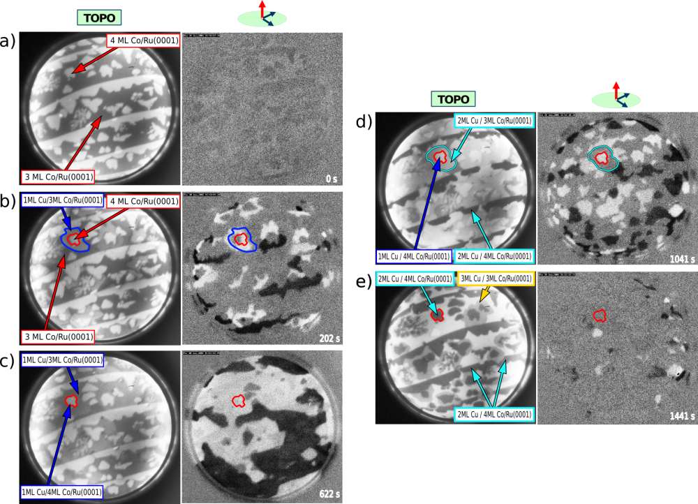
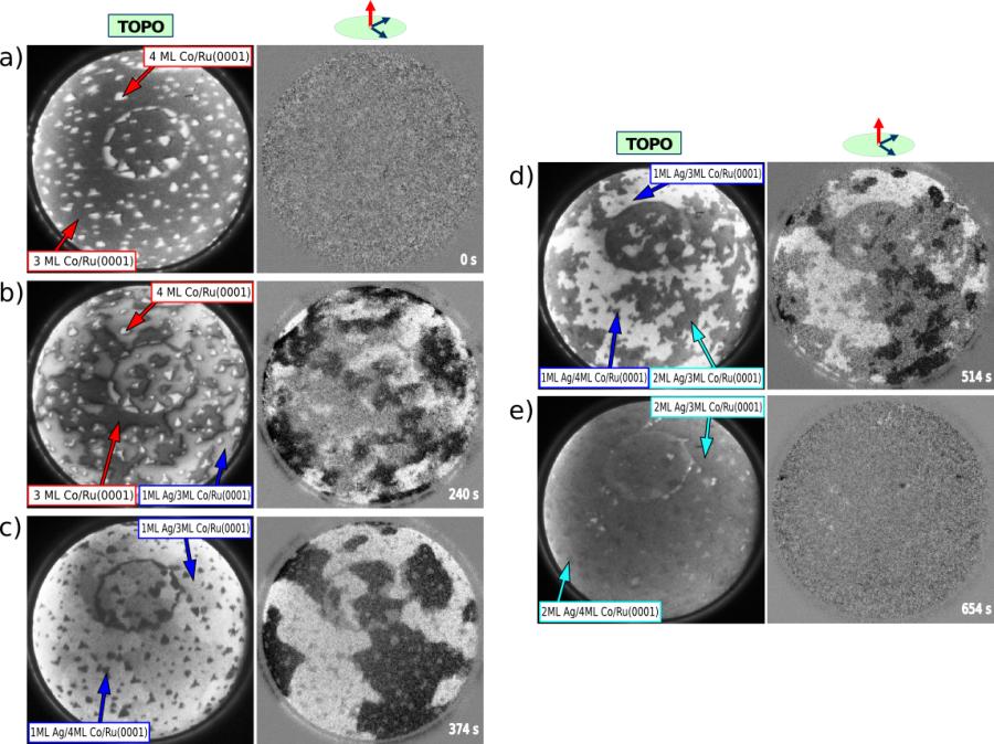
More dramatic effects are observed when we deposit capping layers on top of three monolayer thick Co/Ru(0001) films. We had previously reported[8] how ab-initio calculations show that the in-plane anisotropy of these films is rather small, 0.04 mJ/m2. Indeed, we find that deposition of a single monolayer of any of the coinage metals Ag, Au, or Cu on top of 3 ML Co/Ru(0001) results in an SRT. This effect is demonstrated in experiments summarized in Fig. 3 and Fig. 4, where Ag and Cu were deposited, respectively, on top of Co films with regions of 3 ML and 4 ML thickness. Simultaneous SPLEEM imaging with perpendicular magnetization sensitivity (i.e., with the spin-polarization of the electron beam aligned in the direction perpendicular to the sample surface) during the deposition of the capping layers shows how any out-of-plane component of the magnetization is absent in the bare films, whereas areas covered with a monolayer of Cu or Ag produce strong magnetic contrast, as seen in panels c) and d) of Fig. 3 and Fig. 4 (see also the on-line full movies from which the frames of the figures have been extracted). Similarly, single-monolayer Au caps on 3 ML Co films result in PMA (no images shown here).
When thicker capping layers are deposited on the 3 ML Co films, then the different capping materials lead to qualitatively different results. While 2 ML thick Au cap layers still maintain PMA, bilayer capping layers of either Cu or Ag trigger a second SRT, resulting in an in-plane easy axis of magnetization. This behavior is seen in panels d) and e) of Fig. 3 and Fig. 4 for Ag and Cu, respectively. Quantitative increase of perpendicular anisotropy, as a consequence of non-magnetic capping layers has been reported before, for example for Cu on Co/W films [15]. However, our observations of complete reorientation transitions, induced at the monolayer level by non-magnetic capping layers, seem striking to us. This type of consecutive spin-reorientation transitions is reminiscent of the transitions that occurs for bare Co films when changing the Co thickness from one, to two, and to three atomic layers [8].
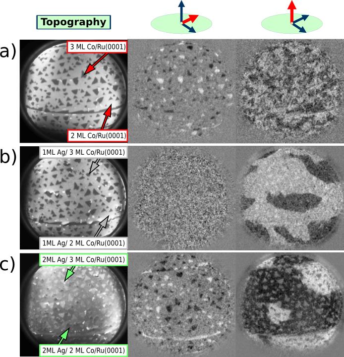
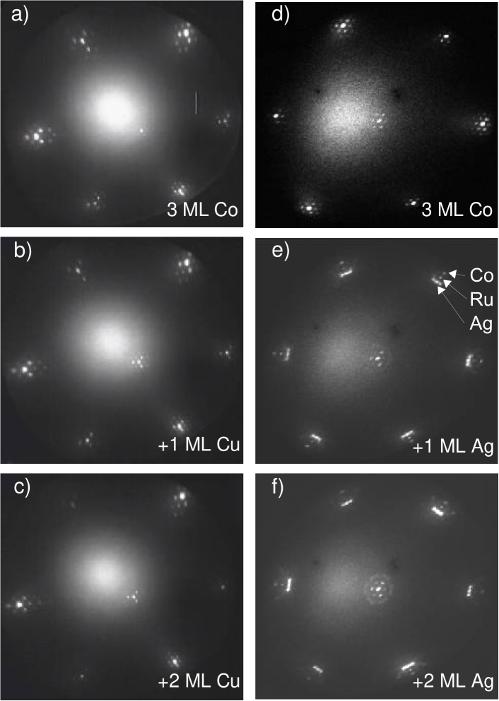
The consecutive SRTs in bare Co films [8] are associated with an abrupt change in lattice spacing from the monolayer films to the thicker films. In order to investigate the role of strain in our capped films, we used low-energy electron diffraction (LEED). In Fig. 5 LEED patterns from 3 ML Co films are reproduced, both with and without Cu and Ag cap layers. The LEED patterns have been acquired in-situ with the low-energy electron microscope[44]. As seen in Fig. 5(a,b), the diffraction pattern of bare 3 ML Co films have several satellite beams around each integer beam. These patterns can be understood as moiré patterns produced by the superposition of the relaxed, bulk-like Co lattice on the underlying Ru lattice. Depositing 1 or 2 Cu layers on these Co films does not produce significant changes in the diffraction patterns [compare Fig. 5(a) to (b,c)]. This implies that the in-plane lattice spacing of the Cu layers is the same as that of the bare Co films, within our error limits (we estimate error limits of the order of 2%, mostly due to the distortions produced by the imaging optics). This observation is consistent with the idea that, as a result of the small lattice mismatch between bulk Co and Cu (close to 1.5%), the strain state of the Co films remains almost unchanged when Cu capping layers are deposited.
In contrast, the lattice mismatch between Co and Ag or Au is large, over 13.6% (Ag and Au have very similar lattice parameters). The magnitude of the mismatch and the fact that the stress is compressive (Ag and Au are larger than Co) suggest that monolayer cap films of Ag or Au on top of Co/Ru(0001) films are likely relaxed. In fact, Ag is known to relax partially when grown directly on Ru, by the introduction of networks of misfit dislocations[45]. We interpret the diffraction patterns found with Ag cap layers [Fig. 5(e,f)] as a superposition of spots corresponding to Ag, Co and Ru [see Fig. 5(e)]. Within the error limit, the separation of spots corresponds to the difference of bulk in-plane lattice parameters of the three metals.
One can immediately appreciate from LEED patterns presented here that the forces that modify the MAE in our capped Co films must include additional factors beyond epitaxial strain. 3 ML Co capped with two monolayers of either Ag or Cu on are magnetized in the same direction (in-plane), even though the lattice spacings inferred from LEED for each capping material differ greatly. On the other hand, the effect of 2 ML Au capping 3 ML Co films is different from Ag, even though the bulk lattice spacings of both capping materials are quite close.
The effect of capping layers on the magnetism of Co films with 4 ML thickness is again richly dependent upon chemical nature and thickness of the cap layer. Ag has the weakest effect on the MA of the Co films, as the in-plane easy-axis of magnetization of the 4 ML Co films remains stable in case of Ag capping layers of any thickness. In the case of Cu, a single cap layer results in PMA while Cu bilayer caps (or thicker films) return the Co magnetization to an in-plane orientation. Au capping layers most strongly modify the MA of 4 ML Co films, 1 – 3 ML Au caps all result in PMA.
When Co films with 5 or 6 ML thickness are capped, only Au affects the MA sufficiently strongly to cause SRTs: 1 – 2 ML Au capping layers result in PMA, and for thicker Au caps the magnetization returns to in-plane. Capping with Ag or Cu fails to produce any change in the easy-axis of magnetization of 5 – 6 ML cobalt films, which remain magnetized in-plane (as the bare 5 – 6 ML films). Finally, we have measured the effect of cap layers on Co films 7 and 8 ML thick. At this Co thickness range, even Au capping fails to produce PMA at any thickness.
The summary of all the observed easy-axes in the different combinations of magnetic film and overlayer material and thickness is shown in table 1. What’s most striking is the observation that capping layers made of the nominally non-magnetic metals silver, copper, and especially gold, appear to enhance perpendicular magnetic anisotropy in Co/Ru(0001)-based structures. In the following section, we discuss how this effect can be understood on the basis of ab-initio theory.
5 Theoretical results
The purpose of the calculations is not only to explain the origin and provide quantitative estimates of the MAE, but to define trends with respect to its complex dependence on the different electronic and structural conditions involved. Although the coinage-metals are all fcc metals, their different in-plane lattice parameters a2D imposes distinct strain conditions in the Co film. Also the atomic number increase from Cu to Ag to Au implies an increasing weight of spin-orbit effects. As we will show here, both factors have a crucial impact on the MAE. Additionally, we will demonstrate the origin of the MA dependence on both the Co and cap films thicknesses, even though the most relevant MA effects occur at the Co/cap interface.
5.1 Capping with 1 ML
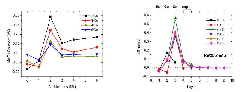
We start by considering Co films of different thicknesses covered by a single coinage metal cap layer. The summary of our results for the MAE of such structures using the a2D of Ru is in figure 6. Notice that in the figure all MAE values are positive, indicating an easy-axis of magnetization along the normal to the surface. The SRT is recovered when a more realistic a2D closer to the Co lattice is used for the thickest films. We will come to this point later. In order to compare the different structures, the MAE has been normalized to the number of Co atoms, which being the magnetic component provides the major contribution. However, the measurements probe the MAE of the entire film, which in the figure would amount to 1 meV for systems with 10 ML of Co. The dependence of the MAE on the Co thickness is governed by the Eb term, as the normalized Edd is an almost constant quantity due to the similar values of the magnetic moments and interatomic distances for a given cap element throughout all Co thicknesses considered.
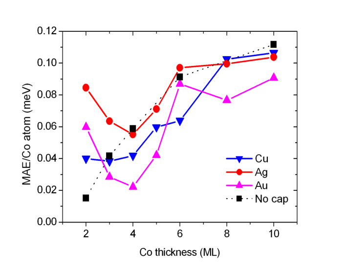
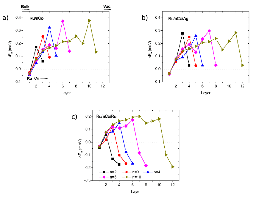
From figure 6 we first note that two different thickness regimes can be defined concerning the effect of one cap layer: for the thinnest Co films, the MAE is considerably enhanced with respect to bare Co, while the opposite holds for thicker Co films. Also the differences introduced by the different cap elements are enhanced at the thin regime. The existence of these two regimes is in the range of the interface effects. The top panels of figure 7 provide the layer resolved Eb contribution to the MAE for the uncapped and Ag covered films. The cases with Cu and Au show a similar layer by layer evolution as Ag. It is evident that the largest contribution comes always from the subsurface layer. In fact the actual value of the MAE (or of the total Eb contribution) can be viewed as a sum of two terms: a pure surface contribution, comprising about 3 layers from the surface plane, and a contribution from the inner layers of the Co slab. In addition, the figure proves that two types of interfaces with opposite contributions to the MA can be distinguished: the outermost interface with either vacuum or a noble metal cap, and the interface with the Ru substrate. As the range of the interface effects are similar for both, the thin regime can be defined as Co films less than 4 layers thick, which can be considered pure interface films. As a result, for these ultrathin films the MAE is highly dependent on the adjacent media.
As shown in the lower panel of figure 7 for the case of a Ru cap layer, the lowering of Eb at the Ru interface is not due to the distance to the surface. Locally Ru reduces Eb, even though the proximity to the surface tends to enhance the MAE, resulting in two inequivalent Co/Ru interfaces for any selected Co thickness. This demonstrates that surface effects must be considered separately from the specific interactions between the materials in contact. Consequently, in the thin film regime, interface effects are not identical to those of a thick film or bulk-like system. The narrowing of the DOS at the surface changes the Co/cap hybridization that ultimately determines the surface contribution to the MAE. The complex mixing of electronic levels induced by the spin-orbit interaction makes difficult to provide a simple assignment of the origin of the MAE in terms of orbital levels by visual inspection of the DOS [46, 47, 48, 49]. Nevertheless, the actual changes are reflected in our layer-resolved mapping of Eb, which shows that while there is a gradual increase of the maximum Eb contribution with the Co thickness for the bare Co film, this trend disappears or significantly reduces in the presence of a cap layer.
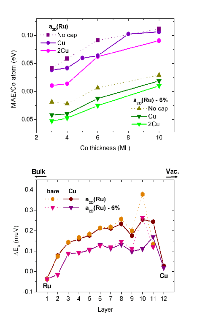
In the thick film regime, the contribution of the inner Co layers to Eb provides both an additive term and a background for the onset of the surface term. In the case of a 2D expanded hcp Co lattice shown in figures 6 and 7, the inner Eb is high and positive, overcoming the Edd contribution and leading to a magnetization normal to the surface. Partially removing the strain of the Co film by reducing a2D towards the Co lattice lowers the value of Eb at the inner layers, and as a result, the MAE is considerably reduced. This is shown in figure 8 both for the bare Co film and for a Cu overlayer, the a2D of Cu being similar to that of Co. The MAE becomes negative except for the thicker Co structures, where a further 2D compression (with the associated MAE reduction) is expected. On the other hand, not only the layer by layer evolution of Eb, but also the local effect of the capping on the surface contributions are the same for both 2D lattices, as can be seen in the lower panel of figure 8. Although the strain and purely electronic effects cannot be disentangled, the ability of our computational scheme to separate the layer contributions helps to identify their influence on the MAE. In fact, the relationship between the MAE and the 2D lattice parameter evidenced here is in good agreement with the well-known experimental evidence of large PMA for thin Co films and multilayers on substrates with a a, like Au or Pt [50, 51, 52, 53, 54].
5.2 Thicker capping
The enhancement of the MA at surfaces is a spin-orbit effect linked to the surface enhancement of the spin and orbital moments, which in turn are due to the band narrowing caused by the loss of atomic neighbors. Intuitively one may expect that by covering a surface with a thick capping would thus reduce the MA. This is in fact the trend for most cap elements studied here (Cu, Ag and also Ru), and the onset of this reduction can already be observed with 2 cap layers (see top panel of figure 8 for the case of Cu).
However, a different situation occurs when the SOC of the cap film becomes important, as is the case of Au. The left panel of figure 9 shows the evolution of the MAE for Co slabs of different thicknesses (from 2 to 6 ML) upon thickening the Au overlayer. It is clear that the maximum MAE per Co atom is obtained with 2 Au cap layers for any Co thickness. In addition, thicker Au cappings always enhance the MAE with respect to the bare Co film. This enhancement is due to the large increase of Eb at the Co/Au interface. This contribution decreases only slightly for increasing Au coverage. This trend is easily seen in the layer resolved contribution shown in the right panel of the figure, corresponding to a Co thickness of 2 ML; similar results are obtained for the thicker Co films. The enhancement of the MAE for a bilayer capping can also be observed for other elements with high SOC, like Pt; however, the unfilled shell of Pt favors a significant induced spin polarization, and this influences the Eb contribution of the Pt layers. Similarly to the case of Ru, this contribution is negative for thick Pt overlayers, and thus balances the high positive term from the Co interface.
The enhancement of the PMA for thick Au caps is in good agreement with the SPLEEM measurements. In addition, we predict that the quantitative value of the MAE per Co atom reaches its highest value for the combination of Au and Co bilayers. Although the additive contribution of the layers provides larger values of the MAE for the thicker films (for example, for a bilayer capping of Au, the total MAE is 0.59 meV for 2 Co layers and 1.35 meV for 10 ML), for these structures the large 2D expansion of the Co film can be considered artificial. As explained in the experimental section, we expect that Au and Co tend to recover their bulk lattice parameters. As shown in figure 8, a compression of the 2D lattice may reduce the perpendicular MA of hcp Co films.
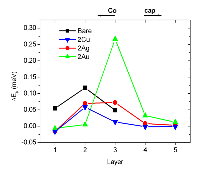
To further explore the effect, we have modelled a semi-infinite Co(0001) surface covered by different thicknesses (1-3 ML) of coinage-metals. It should be kept in mind that Co is ferromagnetic so the exchange interaction energy is several orders of magnitude larger that the MAE. The uniaxial anisotropy is computed using a common magnetization axis for the surface and substrate layers. The resulting easy-axis lies in the surface plane along the [110] direction, in good agreement with the experiments[55, 56]. The local interface effect of covering this surface with a noble metal can be seen in figure 10 for a bilayer capping. Though the surface Eb terms are positive, the addition of the Edd and bulk contributions brings the easy-axis in-plane in all cases. As it occurred for the thick Co/Ru(0001) films, capping reduces the interface Eb except for Au, where a significant enhancement occurs. In fact, as compared to the other Au cap thicknesses, the maximum value of Eb corresponds to a Au capping of 2 ML. This result generalizes the validity of the conclusions obtained here for Co films on Ru(0001). The use of the intermediate a2D of Ru in our calculations may be taken as representative, specially for the dominant surface contribution. In fact, a very rough model to approach the large lattice mismatch between the Co film and the Au cap from the SKKR results would be to take Eb of the inner layers from a calculation using the lattice constant of bulk Co and the surface contribution from an expanded case. This leads to an estimate of the SRT for a Co film capped by 2 ML Au to occur at a Co thickness of ML, in excellent agreement with the SPLEEM measurements.
6 Summary and conclusions
We have determined the easy-axis of magnetization of films composed of several monolayers of Co on Ruthenium, covered with either Ag, Cu or Au. By means of SPLEEM we have observed the changes in the easy axis in real-time and with spatial resolution while growing the coinage metal layers. We demonstrate the possibility of a range of structures that have perpendicular magnetic anisotropy and Curie temperatures well above room temperature.
The resulting MA depends at the same time on the thicknesses of both the magnetic film and the capping overlayer, and on the element chosen as capping metal. Co films between 3 and 6 layers in thickness present consecutive spin-reorientation transitions coupled to the completion of atomic layers, i.e., from in-plane magnetization to perpendicular magnetization as the Co and/or overlayer thickness increases, and to in-plane magnetization again for the thickest films. As compared to bare Co films, capping with 1 ML of Cu and Ag expand the range of Co thicknesses for which PMA occurs. The widest range of PMA is obtained under Au capping, where the second SRT takes place at Co thicknesses of 7 ML for a capping of 1-2 ML of Au, or at 5 ML for more than 2ML Au. Outside of the thickness-range where this rich magnetic behavior is observed, Co bilayers always have perpendicular magnetic anisotropy, irrespective of whether bare or capped with any of the coinage metals. Similarly, coinage metal deposition on Co films thicker than 6 layers does not affect the easy magnetization axis (though in this case the films are magnetized in-plane).
This complex behavior can be understood in terms of the layer-resolved contributions to the magnetic anisotropy energy. Fully relativistic calculations based on the SKKR method allow us to identify two Co thickness regimes defined by the range of the interface effects, which we determine to comprise layers from the interface. For ultrathin films the MAE is governed by the dominant subsurface layer contribution, which significantly increases upon capping by 1 ML of any coinage-metal. At thicker films a different behavior of the surface contribution and that from the inner layers can be identified. The first term is reduced with respect to the thin film regime, evidencing the influence on the MA of the proximity to the surface region. The second term depends on the strain conditions, PMA being favored for expanded 2D Co lattices.
The effect of the capping layer largely depends on the element chosen as overlayer, and especially on the SOC of the cap. This is particularly evident in the dependence of the MAE on the capping film thickness: while thickening the Cu and Ag caps lowers the MAE, high PMA can be obtained for Co films buried under ML of Au, the largest anisotropy corresponding to coverages of 2 ML.
Our results point to the wealth of possibilities to engineer the particular easy-axis in nanometer sized structures that comes about when a precise control of the thickness and structure of magnetic films is available. As a rule, the ingredients to obtain a large PMA in Co films are an expanded 2D lattice, and a thin capping with a metal of high spin-orbit interaction. This can be best achieved with ultrathin films.
References
- [1] J. Stöhr (Author) and H.C. Siegmann. Magnetism: from fundamentals to nanoscale dynamics, volume 152 of Springer Series in Solid-State Sciences. Springer, Berlin, Germany, 1st edition, 2006.
- [2] U. Gradmann. Ferromagnetism near surfaces and thin films. App. Phys., 3(4):161–178, 1974.
- [3] D. Sander. The correlation between mechanical stress and magnetic anisotropy in ultrathin films. Rep. Prog. Phys., 62(5):809–858, 1999.
- [4] D. Sander. The magnetic anisotropy and spin reorientation of nanostructures and nanoscale films. J. Phys.: Condensed Matter, 16(20):R603–R636, 2004.
- [5] K. Ounadjela, D. Muller, A. Dinia, A. Arbaoui, and P. Panissod. Perpendicular anisotropy and antiferromagnetic coupling in Co/Ru strained superlattices. Phys. Rev. B, 45(14):7768–7771, 1992.
- [6] M. Farle. Ferromagnetic resonance of ultrathin metallic layers. Rep. Prog. Phys., 61(7):755–826, JUL 1998.
- [7] Kirsten von Bergmann. Iron nanostructures studied by spin-polarised scanning tunneling microscopy. PhD thesis, Hamburg, 2004.
- [8] F. El Gabaly, S. Gallego, C. Munoz, L. Szunyogh, P. Weinberger, C. Klein, A. K. Schmid, K. F. McCarty, and J. de la Figuera. Imaging spin reorientation transitions in consecutive atomic Co layers. Phys. Rev. Lett., 96:147202, 2006.
- [9] C. Chappert, D. Renard, P. Beauvillain, J. P. Renard, and J. Seiden. Ferromagnetism of very thin films of nickel and cobalt. J. Mag. Mag. Mat., 54-57:795–796, 1986.
- [10] E. Vélu, C. Dupas, D. Renard, J. P. Renard, and J. Seiden. Enhanced magnetoresistance of ultrathin multilayers with perpendicular anisotropy. Phys. Rev. B, 37(1):668–671, Jan 1988.
- [11] V. Grolier, D. Renard, B. Bartenlian, P. Beauvillain, C. Chappert, C. Dupas, J. Ferré, M. Galtier, E. Kolb, M. Mulloy, J. P. Renard, and P. Veillet. Unambiguous evidence of oscillatory magnetic coupling between co layers in ultrahigh vacuum grown Co/Au(111)/Co trilayers. Phys. Rev. Lett., 71(18):3023–3026, Nov 1993.
- [12] B. Újfalussy, L. Szunyogh, P. Bruno, and P. Weinberger. First-principles calculation of the anomalous perpendicular anisotropy in a Co monolayer on Au(111). Phys. Rev. Lett., 77(9):1805–1808, Aug 1996.
- [13] J. Dorantes-Dávila, H. Dreyssé, and G. M. Pastor. Magnetic anisotropy of transition-metal interfaces from a local perspective: Reorientation transitions and spin-canted phases in Pd capped Co films on Pd(111). Phys. Rev. Lett., 91(19):197206, Nov 2003.
- [14] W. Weber, C. H. Back, A. Bischof, D. Pescia, and R. Allenspach. Magnetic switching in cobalt films by adsorption of copper. Nature, 374(6525):788–790, 1995.
- [15] T. Duden and E. Bauer. Influence of Au and Cu overlayers on the magnetic structure of Co films on W(110). Phys. Rev. B, 59(1):468–473, 1999.
- [16] O. Robach, C. Quiros, P. Steadman, K. F. Peters, E. Lundgren, J. Alvarez, H. Isern, and S. Ferrer. Magnetic anisotropy of ultrathin cobalt films on Pt(111) investigated with x-ray diffraction: effect of atomic mixing at the interface. Phys. Rev. B, 65(5):054423, Jan 2002.
- [17] H. J. Elmers, J. Hauschild, and U. Gradmann. Onset of perpendicular magnetization in nanostripe arrays of fe on stepped w(110) surfaces. Phys. Rev. B, 59(5):3688–3695, 1999.
- [18] C. Chappert, K. Le Dang, P. Beauvillain, H. Hurdequint, and D. Renard. Ferromagnetic resonance studies of very thin cobalt films on a gold substrate. Phys. Rev. B, 34(5):3192–3197, Sep 1986.
- [19] J. Dorantes-Dávila, H. Dreyssé, and G. M. Pastor. Magnetic anisotropy of close-packed (111) ultrathin transition-metal films:role of interlayer packing. Phys. Rev. B, 55(22):15033–15042, Jun 1997.
- [20] S. Park, X. Zhang, A. Misra, J. D. Thompson, M. R. Fitzsimmons, S. Lee, and C. M. Falco. Tunable magnetic anisotropy of ultrathin Co layers. App. Phys. Lett., 86(4):042504, 2005.
- [21] S. Gallego and M.C. Mu noz. in preparation.
- [22] L. Szunyogh, B. Újfalussy, C. Blaas, U. Pustogowa, C. Sommers, and P. Weinberger. Oscillatory behavior of the magnetic anisotropy energy in multilayer systems. Phys. Rev. B, 56(21):14036–14044, Dec 1997.
- [23] C. Christides, S. Stavroyiannis, D. Niarchos, M. Gioti, and S. Logothetidis. Dependence of the dielectric function and electronic properties on the co layer thickness in giant-magnetoresistance Co/Au multilayers. Phys. Rev. B, 60(17):12239–12245, Nov 1999.
- [24] H. C. Hsueh, J. Crain, G. Y. Guo, H. Y. Chen, C. C. Lee, K. P. Chang, and H. L. Shih. Magnetism and mechanical stability of -iron. Phys. Rev. B, 66(5):052420, Aug 2002.
- [25] M. Cinal and A. Umerski. Magnetic anisotropy of vicinal (001) fcc Co films: Role of crystal splitting and structure relaxation in the step-decoration effect. Phys. Rev. B, 73(18):184423, 2006.
- [26] H. Hashizume, K. Ishiji, J. C. Lang, D. Haskel, G. Srajer, J. Minar, and H. Ebert. Observation of x-ray magnetic circular dichroism at the Ru K edge in Co-Ru alloys. Phys. Rev. B, 73(22):224416, 2006.
- [27] K. Himi, K. Takanashi, S. Mitani, M. Yamaguchi, D. H. Ping, K. Hono, and H. Fujimori. Artificial modulation of magnetic structures on a monatomic layer scale in Co/Ru superlattices. App. Phys. Lett., 78(10):1436–1438, 2001.
- [28] H. F. Ding, A. K. Schmid, D. J. Keavney, Dongqi Li, R. Cheng, J. E. Pearson, F. Y. Fradin, and S. D. Bader. Selective growth of Co nanoislands on an oxygen-patterned Ru(0001) surface. Phys. Rev. B, 72(3):035413, 2005.
- [29] C. Song, X. X. Wei, K. W. Geng, F. Zeng, and F. Pan. Magnetic-moment enhancement and sharp positive magnetoresistance in Co/Ru multilayers. Phys. Rev. B, 72(18):184412, 2005.
- [30] Joseph E. Davies, Olav Hellwig, Eric E. Fullerton, and Kai Liu. Temperature-dependent magnetization reversal in (Co/Pt)/Ru multilayers. Phys. Rev. B, 77(1):014421, 2008.
- [31] E. Bauer. Low energy electron microscopy. Rep. Prog. Phys., 57(9):895–938, 1994.
- [32] T. Duden and E. Bauer. Spin-polarized low energy electron microscopy. Surf. Rev. Lett., 5(6):1213–1219, 1998.
- [33] F. El Gabaly, J. Puerta, C. Klein, A. Saa, A. Schmid, K. McCarty, J. Cerda, and J. de la Figuera. Structure and morphology of ultrathin Co/Ru(0001) films. New J. Phys., 9, 2007.
- [34] W. L. Ling, T. Giessel, K. Thurmer, R. Q. Hwang, N. C. Bartelt, and K. F. McCarty. Crucial role of substrate steps in de-wetting of crystalline thin films. Surf. Sci., 570(3):L297–L303, 2004.
- [35] T. B. Massalski, editor. Binary Alloy Phase Diagrams. ASM International, Ohio, USA, 2nd edition, 1990.
- [36] L. Z. Mezey and J. Giber. The surface free-energies of solid chemical-elements – calculation from internal free enthalpies of atomization. Japanese Journal of Applied Physics Part 1, 21(11):1569–1571, 1982.
- [37] A. Christensen, A. V. Ruban, P. Stoltze, K. W. Jacobsen, H. L. Skriver, J. K. Norskov, and F. Besenbacher. Phase diagrams for surface alloys. Phys. Rev. B, 56(10):5822–5834, 1997.
- [38] G. E. Thayer, V. Ozolins, A. K. Schmid, N. C. Bartelt, H. Asta, J. J. Hoyt, S. Chiang, and R. Q. Hwang. Role of stress in thin film alloy thermodynamics: Competition between alloying and dislocation formation. Phys. Rev. Lett., 86(4):660–663, Mar 2001. stress, surface alloy, Sandia.
- [39] G. E. Thayer, N. C. Bartelt, V. Ozolins, A. K. Schmid, S. Chiang, and R. Q. Hwang. Linking surface stress to surface structure: Measurement of atomic strain in a surface alloy using scanning tunneling microscopy. Phys. Rev. Lett., 89:036101, Jul 2002.
- [40] A. K. Schmid, J. C. Hamilton, N. C. Bartelt, and R. Q. Hwang. Surface alloy formation by interdiffusion across a linear interface. Phys. Rev. Lett., 77(14):2977–2980, 1996.
- [41] E. Duden, T.and Bauer. A compact electron-spin-polarization manipulator. Rev. Sci. Inst., 66(4):2861–2865, APR 1995. spleem.
- [42] R. Ramchal, A. K. Schmid, M. Farle, and H. Poppa. Spiral-like continuous spin-reorientation transition of fe/ni bilayers on Cu(100). Phys. Rev. B, 69:214401, 2004.
- [43] J. Zabloudil, R. Hammerling, L. Szunyogh, and P. Weinberger. Electron Scattering in Solid Matter: a theoretical and computational treatise. Springer-Verlag, 2005.
- [44] J. de la Figuera, F. El Gabaly, J. M. Puerta, J. I. Cerda, and K. F. McCarty. Determining the structure of Ru(0001) from low-energy electron diffraction of a single terrace. Surf. Sci., 600:L105, 2006.
- [45] Herringbone, Au triangular patterns of dislocations in Ag, and AgAu alloy films on Ru(0 0 0 1). W.l. ling and j.c. hamilton and k. thürmer and g.e. thayer and j. de la figuera and r.q. hwang and c.b. carterb and n.c. bartelt and k.f. mccarty. Surf. Sci., 600:1735–1767, 2006.
- [46] J. Stöhr. Exploring the microscopic origin of magnetic anisotropies with x-ray magnetic circular dichroism (XMCD) spectroscopy. J. Mag. Mag. Mat., 200:470–497, 1999.
- [47] D. Weller, J. Stöhr, R. Nakajima, A. Carl, M. G. Samant, C. Chappert, R. Mégy, P. Beauvillain, P. Veillet, and G. A. Held. Microscopic origin of magnetic anisotropy in Au/Co/Au probed with x-ray magnetic circular dichroism. Phys. Rev. Lett., 75(20):3752–3755, Nov 1995.
- [48] M. Sawada, K. Hayashi, and A. Kakizaki. Electronic structure and magnetic anisotropy of Co/Au(111): a spin-resolved photoelectron spectroscopy study. Phys. Rev. B, 63(19):195407, Apr 2001.
- [49] C. Andersson, B. Sanyal, O. Eriksson, L. Nordstrom, O. Karis, D. Arvanitis, T. Konishi, E. Holub-Krappe, and J. Hunter Dunn. Influence of ligand states on the relationship between orbital moment and magnetocrystalline anisotropy. Phys. Rev. Lett., 99(17):177207, 2007.
- [50] J. Kohlhepp and U. Gradmann. Magnetic surface anisotropies of Co(0001)-based interfaces from in situ magnetometry of Co films on Pd(111), covered with ultrathin films of Pd and Ag. J. Mag. Mag. Mat., 139:347–354, 1995.
- [51] Akihiro Murayama, Kyoko Hyomi, James Eickmann, and Charles M. Falco. Underlayer-induced perpendicular magnetic anisotropy in ultrathin Co/Au/Cu(111) films: A spin-wave brillouin-scattering study. Phys. Rev. B, 58(13):8596–8604, Oct 1998.
- [52] M. Wojcik, C. Christides, E. Jedryka, S. Nadolski, and I. Panagiotopoulos. Formation of a co nanostructure revealed by nuclear magnetic resonance measurements in Co/Au multilayers. Phys. Rev. B, 63(1):012102, Dec 2000.
- [53] F. C. Chen, Y. E. Wu, C. W. Su, and C. S. Shern. Ag-induced spin-reorientation transition of Co ultrathin films on Pt(111). Phys. Rev. B, 66(18):184417, Nov 2002.
- [54] Y. L. Iunin, Y. P. Kabanov, V. I. Nikitenko, X. M. Cheng, D. Clarke, O. A. Tretiakov, O. Tchernyshyov, A. J. Shapiro, R. D. Shull, and C. L. Chien. Asymmetric domain nucleation and unusual magnetization reversal in ultrathin Co films with perpendicular anisotropy. Phys. Rev. Lett., 98(11):117204, 2007.
- [55] J. Unguris, M. R. Scheinfein, R. J. Celotta, and D. T. Pierce. Magnetic microstructure of the (0001) surface of hcp cobalt. Appl. Phys. Lett., 55:2553–2555, 1989.
- [56] S. Pick et al. A tight-binding study of surface magnetic anisotropy of the Co (0001) and its perturbation by Cu and CO. Sol. Stat. Comm, 127:531–534, 2003.