A Simple Method for Rise-Time Discrimination of Slow Pulses from Charge-Sensitive Preamplifiers
Abstract
Performance of a simple method of particle identification via pulse rise time discrimination is demonstrated for slow pulses from charge-sensitive preamplifiers with rise times ranging from 10 ns to 500 ns. The method is based on a comparison of the amplitudes of two pulses, derived from each raw preamplifier pulse with two amplifiers with largely differing shaping times, using a fast peak-sensing ADC. For the injected charges corresponding to energy deposits in silicon detectors of a few tens of MeV, a rise time resolution of the order of 1 ns can be achieved. The identification method is applicable in particle experiments involving large-area silicon detectors, but is easily adaptable to other detectors with a response corresponding to significantly different pulse rise times for different particle species.
pacs:
21.65+f, 21.60.Ev, 25.70.PqI Introduction
Pulse-shape discrimination is a well known technique often used to identify particles according to their atomic and mass numbers. The method is based on the characteristic time-dependence of the electrical or optical response they generate in the detectors. There are different physical effects responsible for the sensitivity of different detectors on the species of impinging particles. Accordingly, many different pulse-shape discrimination methods have been devised.In particular, the sensitivity of semiconductor detectors to different particles is due to the variation of the ionization density along the particle track in the detector material and the resulting temporal variation of the charge collection rate in the applied electric field.
The present study is inspired by the actual demand of measuring rise times of pulses produced by charged particles in large-area silicon detectors now used in multidetector arrays such as the CHIMERA telescope array chi . The study focuses on an idea of measuring rise times of slow pulses from charge-sensitive preamplifiers by shaping (filtering) these pulses with two different timing constants, one of which is much longer than the relevant maximum rise time, while the other is of the order of the shortest rise time expected in the particular application. With proper shaping, the amplitude of the “slow” pulse (representing the total charge injected into the preamplifier) will be virtually independent of the rise time of the raw preamplifier pulse, while the amplitude of the “fast” pulse (representing the fraction of charge injected on a short timescale) will show a distinct dependence on the rise time of the preamplifier pulse. Subsequently, the amplitudes of both shaped pulses can be digitized by fast peak-sensing Analog to Digital Converters (ADCs), such as, e.g., the Phillips 7164 phi or Silena sil modules. Alternatively, depending on the available data acquisition, both shaped pulses can be stretched and their amplitudes be measured using current-integrating ADCs (QDC). Ultimately, the rise time is determined, event-by-event, from the ratio of “fast” to “slow” pulse amplitudes.
II The Test Setup
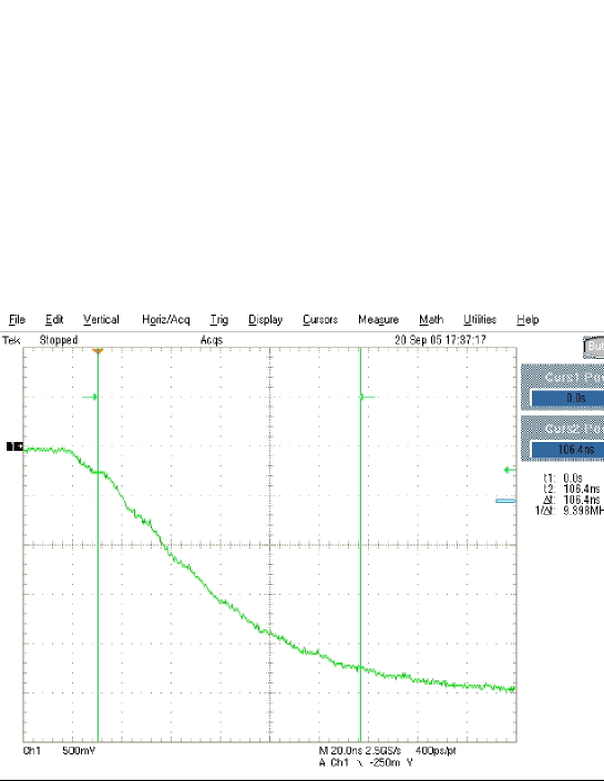
A block diagram of the test setup is shown in Fig. 1. As depicted in this diagram, calibrated charge was injected into an ORTEC 142A charge-sensitive preamplifier, with three different rates, resulting in preamplifier output signals that had nominal rise times of 50, 100, and 200 ns, respectively. Charge pulses were obtained by charge-terminating pulses from a precision ORTEC 448 pulse generator. Different pulse rise times were employed as defined by the rise time settings of the pulse generator, while the decay time was fixed at 50 s. A typical pulse with a nominal (set on the pulse generator module) rise time of 100 ns is illustrated in Fig. 2. It is seen to have an actual rise time close to nominal.
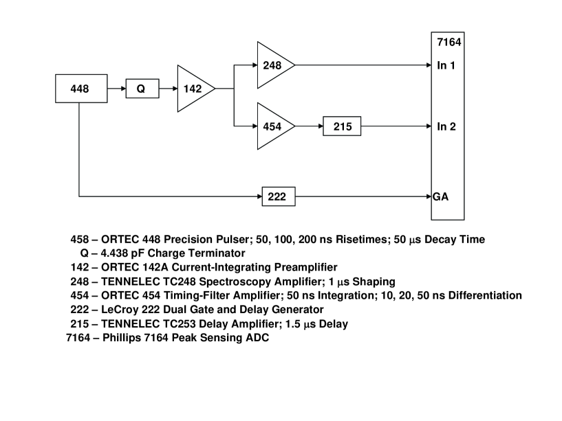
The output signal from the preamplifier was routed into two spectroscopic channels characterized by different shaping times. The “slow” channel had a shaping time fixed at 1 s, while for the “fast” channel differentiation times of 10, 20, and 50 ns were explored. The integration time of the ORTEC 454 timing filter amplifier (TFA) used in the “fast” channel was fixed at 50 ns.
To be able to use a common ADC gate for both, fast and slow pulses, a TC215 delay amplifier was used in the fast channel to delay the output pulse from the ORTEC 454 TFA. The resulting timing of fast and slow pulses at the input of the peak sensing Phillips 7164 ADC is illustrated in FIG. 3. The present setup requires a peak sensing ADC capable of digitizing pulses with 50-ns short rise times, hence the choice of the Phillips 7164 ADC module.

III Results and Analysis
The measurements were performed for series of pulses with rise times of 50 ns, 100 ns, and 200 ns and for shaping times for the “fast” response of 10 ns, 20 ns, and 50 ns. To assess the effect of inherent fluctuations in the amount of charge ()injected into the preamplifier, the latter charge was varied in the range from 0.222 pC to 3.55 pC, corresponding to energy deposits in a silicon detector in the range from 5 MeV to 80 MeV.

Results of the measurements are illustrated in Figs. 4, 5, 6, and 7. Fig. 4 illustrates the dependence of the amplitude () of the “fast” pulse on the injected charge (), as measured for different shaping and rise times denoted by time constants and , respectively. As seen in this figure, shorter shaping times provide for a better separation of faster pulses, a trend that agrees qualitatively with what is expected based on the principles of filtering.
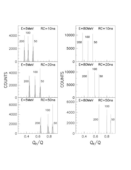
A more quantitative measure of the pulse-shape discrimination performance of the method over a range of injected charges is seen in Fig. 5, where spectra of the ratios of the amplitudes () of “fast” pulses to the amplitudes () of the corresponding “slow” pulses are displayed for various shaping times. As expected, the resolution of the method deteriorates with decreasing amount of injected charge. Again, short shaping times are seen to provide for a larger spread between pulses of short rise times, at the expense of a loss in the amplitude () of “fast” pulses.

The relative widths of the peaks seen in Fig. 5 are plotted in Fig. 6 vs. injected charge for different shaping and rise times. The charge is expressed in units of MeV of equivalent energy deposit for silicon. As seen in this figure, the relative resolution is almost equally good for 10-ns and 20-ns shaping times. The resolution is better than 1% over most of the range of injected charges, except for the smallest one.

Fig. 7 illustrates the absolute resolution in rise time in units of nanoseconds, achieved for different amounts of injected charge () and for different shaping and rise times. As seen in this figure, for the range of rise times explored, the 10-ns and 20-ns shaping times offer an almost equally good resolution of a few ns, over much of the range in charges explored. The weak but steady deterioration of the resolution with decreasing amount of charge injected, comes from the relative increase in statistical fluctuation in charge. It is encouraging that, except for the lowest charges injected, the resolution is of the order of a few ns, and is approximately 1 ns for the range of energies involved in typical experiments.
IV Conclusions
A simple and economical method has been demonstrated for rise time discrimination of pulses from charge sensitive preamplifiers. The method is based on measurements of the amplitudes of pulses derived from the raw preamplifier pulses by shaping with different time constants. It is shown to provide for a very good resolution in rise times. The method requires no fine tuning of the electronics circuitry involved and should, therefore, be well suited for multi-detector systems. In the present study, a timing filter amplifier was used to produce the “fast” signal. In fact, a most primitive RC differentiator should perform sufficiently well, provided its output amplitude is matched to the range of the available ADC. The present design processes pulses from charge-sensitive preamplifiers used with solid-state detectors, but the method can easily be adapted to other systems such as scintillation detectors providing pulses with significantly different rise times.
Acknowledgements.
This work was supported by the U.S. Department of Energy grant No. DE-FG02-88ER40414.References
- (1) eprint http://www.lns.infn.it/research/chimera/index.html.
- (2) eprint http://www.phillipsscientific.com/phisci1.htm.
- (3) eprint http://www.geocities.com/silenaspa/4418V.htm.