Loading of large ion Coulomb crystals into a linear Paul trap incorporating an optical cavity for cavity QED studies
Abstract
We report on the loading of large ion Coulomb crystals into a
linear Paul trap incorporating a high-finesse optical cavity
(). We show that, even though the 3-mm
diameter dielectric cavity mirrors are placed between the trap
electrodes and separated by only 12 mm, it is possible to produce
in situ ion Coulomb crystals containing more than 105
calcium ions of various isotopes and with lengths of up to several
millimeters along the cavity axis. We show that the number of ions
inside the cavity mode is in principle high enough to achieve
strong collective coupling between the ion Coulomb crystal and the
cavity field. The results thus represent an important step towards
ion trap based Cavity Quantum ElectroDynamics (CQED)
experiments using cold ion Coulomb crystals.
PACS 32.80.Fb; 37.10.Ty; 42.50.Pq;
1 Introduction
In recent years there has been much focus on light-matter
interactions at the level of single photons, primarily motivated
by applications within quantum information science, where an
efficient light-matter interface is indispensable for many
applicationsCirac_97 ; Duan_01 . Of particular interest has
been the so-called strong coupling regime of Cavity Quantum
ElectroDynamics (CQED)Berman , in which the rate of coherent
evolution within the system exceeds that of any dissipative
processes, making this regime ideal for the quantum engineering of
light-matter interfaces. A strong collective coupling between a
medium of atoms and the light field can be achieved if the
single atom-photon coupling strength is large enough to
satisfy the inequality , where
and are the decay rates of the atomic dipole and the
cavity field, respectively. For optical frequencies, experiments
with neutral atoms have been extremely successful and have reached
the strong coupling regime for single atomsKimble_98 . Such
experiments benefit from the use of cavities of extremely small
mode volumes to increase the single atom-photon coupling strength,
given by:
,
where is the transition dipole moment, is the
frequency of the transition and is the mode volume of the
cavity. However, since the cavity decay rate is inversely
proportional to the cavity length, such experiments require very
high finesse cavities, which are technically challenging to
operate. One further complication of such experiments is the
difficulty in efficiently trapping and confining the neutral atoms
inside the cavity. While short-time solutions to this problem have
recently been foundBoozer_06 ; Puppe_07 , ions, by contrast,
can be stored for hours in ion traps and offer relatively easy
access to a regime in which the spatial extent of their wave
packet is well-localized on the scale of the optical wavelength of
their atomic transition (Lamb-Dicke regime). Though experiments
with single ions in cavities have confirmed
thisKeller_2003 ; Mundt_2003 , the strong coupling regime has
not yet been reached, mainly due to the difficulty in lowering the
mode volume, i.e. minimizing the mirror separation, without
severely modifying the trapping potential, which makes trapping
extremely challenging. The requirement of a small mode volume can
be relaxed for ensembles of atoms or ions due to the
factor entering in the collective coupling strength of the
ensemble. This means that a technically less demanding longer
cavity with a lower finesse can be used in such
experiments.
In addition to the issue of tight
confinement and long storage time, ion Coulomb crystals have a
number of advantages over cold atomic samples. As the ions are
confined in a crystal lattice, the decoherence rate due to
collisions is very low. Furthermore, the lattice structure in
conjunction with the standing wave field of the optical resonator
might be interesting for the engineering of the atom-photon
interaction. Whereas spatial structuring would require the use of
optical lattices for neutral atoms it is inherent in an ion
Coulomb crystal and as described in a recent
paperMortensen_07 , the structure of ion Coulomb crystals
can be made very regular and periodic. Finally, the low optical
density of the ion Coulomb crystal ()
makes optical pumping and state preparation unproblematic.
In this paper we focus on the production and characterization of large cold ensembles of ions, specifically ion Coulomb crystals, of up to hundreds of thousands of ions in a linear Paul trap incorporating a high finesse optical cavity designed for CQED experiments. We show that it is possible to insert cavity mirrors in between the trap electrodes without significantly perturbing the trapping fields, that the ion Coulomb crystals can be produced in a clean and efficient way that preserves the finesse of the cavity, and that the number of ions in the cavity mode can be high enough to potentially satisfy the strong coupling criterion, . These results thus represent an important step towards ensemble-based CQED with ion Coulomb crystals and open up for the use of such media as a tool for quantum information processingMortensen_thesis ; Herskind_proceedings ; Coudreau_07 .
The paper is organized as follows: In section 2, we describe our linear Paul trap along with the integrated cavity. In section 3, we describe the loading scheme used for the production of the Coulomb crystals of calcium ions and present results on loading of the trap with various naturally abundant calcium isotopes. In section 4, we address the issue of optimization of the loading in terms of maximizing the total number of ions within the cavity mode volume. In section 5, we conclude.
2 Experimental setup
1!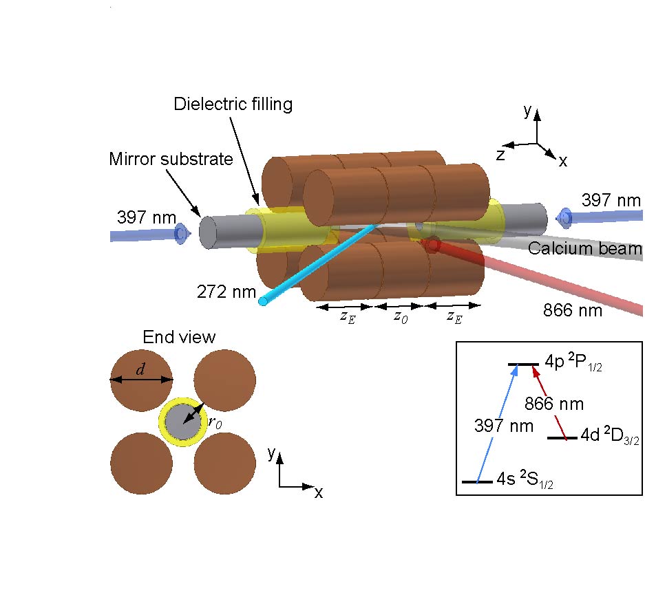
Fig. 1 shows a sketch of the setup used in the experiments. The trap is a linear Paul trapPrestage_89 which consists of four sectioned cylindrical electrode rods placed in a quadrupole configuration. The length of the center-electrode is mm, and the length of the end-electrodes is mm. The electrode diameter is mm and the distance from the trap center to the electrodes is mm. Confinement in the radial plane (-plane in Fig. 1) is obtained by applying time varying voltages and to the two sets of diagonally opposite electrode rods. The sectioning of each of the electrode rods allows for application of a static voltage, , to the end-electrodes, which provides confinement along the -axis. The potential along the -axis is well described by
| (1) |
where and are the mass and charge of the ion and is a constant related to the trap geometry. For one can introduce an effective or pseudo-potential in the radial plane described byDrewsen_00
| (2) |
In such a three-dimensional potential, one finds that the density of ions in an ion Coulomb crystal is controlled only by the rf-voltage and given byHornekaer_01
| (3) |
The trap is operated at a frequency MHz and the end-voltage, , is typically 1 to 10 V. The rf voltage, , is typically between 100 and 400 V, which leads to ion densities between and cm-3.
The unique feature of this trap is the incorporation of a high finesse optical cavity, with mirrors situated in between the electrodes. The cavity is designed for operating on the 4d 2D3/24p 2P1/2 transition of 40Ca+ at 866 nm (see insert Fig. 1). The mirrors, both with a radius of curvature of 10 mm, are placed in a near-confocal geometry supporting a standing wave mode of light at 866 nm with a waist of m at the trap center. The transmission of the two mirrors is 1500 ppm and 5 ppm at 866 nm, respectively. The cavity finesse at 866 nm is determined by measuring the free spectral range (FSR) and the width of the resonance peak. The FSR is measured to be GHz, corresponding to a cavity length of 11.8 mm. This value was obtained by tuning the laser frequency over one FSR of the cavity while recording the number of (known) FSR of a longer reference cavity. The width of the resonance peak is found to be MHz by comparing the width with sidebands at 5 MHz. The resulting finesse is then . This is also consistent with the incoupling mirror transmission of 1500 ppm and intra-cavity losses of 350 ppm, which we derived from the cavity reflection signal. The intra-cavity loss is due to mirror contamination introduced mainly during degassing of the ion pump connected to the vacuum chamber and will be avoided in the future by inserting a valve between the ion pump and the trap chamber. This should allow for intra-cavity loss of only a few tens of ppm. Based on the measurements quoted above, we deduce a cavity decay rate of MHz. From the spontaneous decay rate, , of the excited 4p 2P1/2 state of 40Ca+, the decay rate for the atomic dipole is MHz. From the dimensions of the cavity, the ion-photon coupling strength of a single 40Ca+ ion at the cavity waist and field anti-node is expected to be MHz. In principle it thus requires ions within the cavity mode volume to enter a regime governed by a strong collective coupling (where is satisfied).
3 Loading of the trap
In order to efficiently load large crystals into the trap we employ the technique of resonance-enhanced photoionizationKjaergaard_00 . As compared to conventional electron bombardment, this method has several advantages which are all essential to the experiment. First of all, the problem of charging surrounding isolating materials, e.g. mirror substrates, is greatly reduced as only a single electron is produced per ionKjaergaard_00 ; Brownnutt_07 . Secondly, the ionization efficiency can be made much higher, leading to loading rates which are significantly higher than what can be achieved with electron bombardmentHendricks_07 . This makes loading at a lower atomic flux practicalGulde and thus reduces the risk of contaminating both the trap electrodes and closely spaced delicate objects, such as the mirrors integrated into the ion trap. While deposition of material on the electrodes is suspected to give rise to heating of the ions Deslauriers_06_1 ; Devoe_02 , contamination of the mirrors will be devastating to the quality of the resonator. Finally, the technique can be extremely isotope selectiveMortensen_04 allowing for loading of different isotopes in well-controlled ratios.
The level scheme used in this work for photoionization is presented in Fig. 2. A single UV-light source at 272 nm ionizes atomic calcium in a two-photon process through resonant excitation of the 4s5p 1P1 state followed by absorption of a second 272 nm photon from either the 4s5p 1P1 state or the 4s3d 1D2 state (populated through spontaneous emission) into the continuum (see Fig. 2) Kjaergaard_00 ; Mortensen_04 . The light at 272 nm originates from a laser system based on a commercial Ytterbium-doped DFB fiber laser that has been frequency doubled twice to produce light at the fourth harmonic. The DFB fiber laser system was described in detail in a recent paperHerskind_07 . In brief, light from a CW DFB fiber laser operating at 1088 nm is first frequency doubled in a bow-tie cavity containing a LiNbO3 crystal to produce light at 544 nm. This light is subsequently frequency doubled in a bow-tie cavity containing a -BaBa2O4 crystal to finally produce light at 272 nm. Frequency tuning can be achieved by controlling the length of the fiber laser cavity either with a piezoelectric transducer (PZT), or by changing the temperature.
1!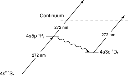
For loading of the trap, a thermal beam of atomic calcium with a cross section of mm2 is intersected by the 272 nm laser beam in the center of the trap at right angles in order to minimize Doppler broadening. The atomic beam is produced from an effusive oven followed by a series of skimmers, inserted to avoid deposition of calcium on the trap electrodes and cavity mirrors. The UV-beam has a power of about 20 mW and a waist of m at the trap center. The ions produced are then Doppler laser cooled on the 4s 2S1/24p 2P1/2 transition along the trap axis (z axis in Fig. 1) by two counter propagating beams at 397 nm (beam diameter 1 mm), while in the radial plane (xy-plane in Fig. 1) the ions are sympathetically cooled through the Coulomb interaction. An 866 nm beam, resonant with the 4d 2D3/24p 2P1/2 transition, is applied to prevent the ions from being shelved into the metastable D3/2 state (see insert of Fig. 1). Typically, 8-10 mW of 397 nm light detuned by MHz below resonance is used during loading. Both power and detuning are then decreased upon completion of the loading in order to optimize the cooling. Detection of the ions is performed by imaging spontaneously emitted light at 397 nm onto an image intensified CCD camera located above the trap in Fig. 1. The number of ions loaded can then be deduced from the recorded images by the method described in Ref. Madsen_00 .
1!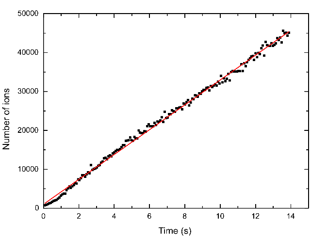
Fig. 3 shows the number of loaded ions versus time when the frequency of the 272 nm light source is tuned close to the resonance of the 4s2 1S04s5p 1P1 transition of 40Ca. The end- and rf-voltages were =3.9 V and =130 V, respectively ( kHz and kHz), and the oven temperature during the loading sequence was C. As can be seen from the figure, we are able to load in the excess of 3000 ions/s at this relatively low oven temperature. This means that Coulomb crystals with more than ions can be produced within a minute. Fig. 4 shows an example of such a crystal, where the total number of ions is 88000 and the density and length of the crystal are and 3 mm, respectively.
1!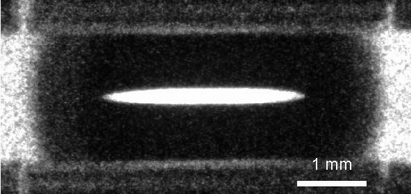
A potentially attractive feature of ion Coulomb crystal based CQED is the possibility to work with crystals of various isotope contents. Two-component crystals are especially interesting for CQED studies since they allow for laser cooling one component (outer, radially separated component) while having the other component (inner cylindrical component) interacting with the cavity field only. By tuning our 272 nm light source to resonance with the respective transitions of specific isotopes of calcium, we have loaded such two-component crystals consisting of 40Ca+ and isotopes of higher mass numbers. When producing MCa+, where , 40Ca+ ions are also created through an electron charge transfer process between atoms in the atomic beam, dominated by 40Ca, and the ions in the trapMortensen_04 . This process has the form, 40Ca+MCa+ 40Ca++MCa+EM and is nearly resonant in the sense that lies much below the energy associated with the thermal collisions leading to the exchange process. The relative content of 40Ca+ and less naturally abundant isotopes in the crystal can be controlled to a high degree by turning on the atomic beam after the ionization laser has been turned off. Due to the mass dependence of the radial trapping potential (c.f. eq. 2) the different isotopes separate radially when cooled into an ion Coulomb crystalHornekaer_01 . This is clearly seen in Fig. 5a) where both 40Ca+ and 44Ca+ ions are laser cooled simultaneously. In Fig. 5b) and c) the cooling lasers have been applied only to one component, while the other is being sympathetically cooled.
1!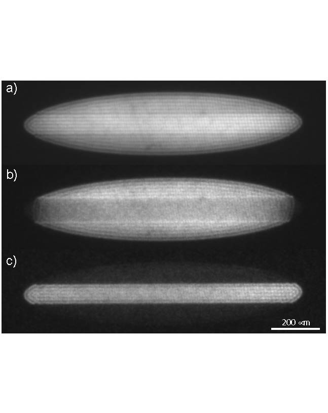
Two-component crystals of 40Ca+ ions and all other naturally abundant isotopes of calcium (except 46Ca+ which has a natural abundance of only Emsley_95 ) have been produced through the charge transfer process described above, as seen in Fig. 6. The laser system is capable of covering the entire spectrum of naturally abundant calcium and allows for easy and quick changing from one isotope to another, which makes CQED studies with such two-components crystals practical. The relevant transition for the CQED experiments on this system is the 4d2D3/24p2P1/2 transition of Ca+. The isotope shift of this transition, relative to 40Ca+, is 4.5 GHz for 44Ca+, which means that 40Ca+ should not be affected by the cooling lasers when this component is being sympathetically cooled by the 44Ca+ ions. However, with our loading scheme we have the possibility to work with 48Ca+ instead of 44Ca+ which has an even larger isotope shift of 8.3 GHz.Nortershauser_98
1!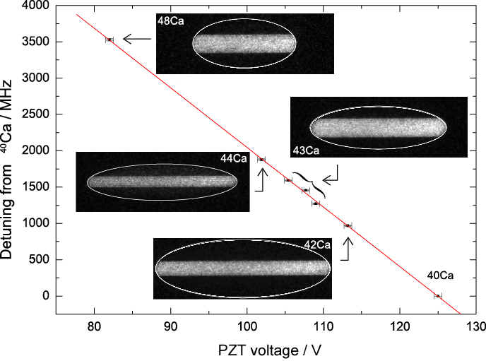
As mentioned previously, compared to electron bombardment, the method of resonant photoionization minimizes charging effects as well as trap contamination and formation of patch potentials. From the images shown in Fig. 5 and 6), there appears to be no visible perturbation on the shape caused by such effects. In Fig. 5 the upper and lower boundaries of the inner component have been measured to be parallel at least to within 2 mrad, indicating that the introduction of cavity mirrors inside a linear Paul trap does not significantly perturb the trapping of such crystals. Furthermore, as the high-finesse cavity constitutes an excellent detector of trap contamination, the observation that the finesse has not degraded during the loading process confirms the cleanliness of the loading technique.
4 Optimizing the total number of ions inside the cavity mode
As mentioned in the introduction, one of the main challenges for the realization of CQED with ion Coulomb crystals is to load a large number of ions into the cavity mode to enhance the collective atom-light coupling. For our trap, with the optical cavity axis coinciding with the trap axis, the highest number of ions in the cavity mode is achieved when the product of the crystal length and the density, , is maximized. The length is controlled by both the end- and rf-voltage, whereas the density is determined solely by the rf-voltage (c.f. eq. 3). Ideally, we would therefore wish to work at a very low and a very high . In practice, we find that the crystals become unstable at lengths above a few mm, although the exact length is very dependent on the rf-voltage and on the total number of ions in the crystal as well as the level of cooling power. In qualitative terms, we interpret this as a result of rf-heating in the crystalBlumel_89 ; Schiffer_00 . This heating drives the radial motion of the ions, while the laser cooling beams act only directly along the trap axis (see Fig. 1). Since the coupling between axial and radial motion is weaker for longer than for shorter prolate crystals, compensation of rf-heating by axial laser cooling is less efficient in longer prolate crystals. Increasing the cooling power may help to confine longer crystals containing more ions, however, there is ultimately a tradeoff between the maximal attainable length, the total number of crystalized ions, and the ion density. Fig. 7 shows the maximal attainable number of ions in the cavity mode111 is defined through the definition of the collective coupling strength , where the standing wave TEM00 mode function is given by and where the integral is evaluated over the crystal length, . With this definition ., , as a function of rf-voltage, , (density, ). Each point was found by lowering the end-voltage and letting the crystal expand axially until it became unstable and was lost. The number of ions in the cavity mode is found to be maximal for rf-voltages around 350 V ( cm-3). Here, more than 2000 ions are in the cavity mode, which would correspond to a collective coupling strength of MHz. The dashed line in the figure indicates the level above which the number of ions becomes large enough to satisfy the strong collective coupling criterium.
1!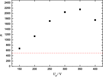
5 Conclusion
We have achieved efficient in situ loading of large ion
Coulomb crystals in a linear Paul trap with an integrated optical
resonator. This work demonstrates that such a high finesse optical
cavity can be incorporated into a linear Paul trap without
impeding the trapping of large ion Coulomb crystals, that these
crystals can have lengths comparable to that of the cavity (more
than one third of the cavity length) and that the finesse of the
cavity is preserved by
the method of resonant photoionization.
We have investigated the optimal trapping parameters for
maximizing the number of ions in the cavity mode and found that
more than 2000 ions could be confined in the cavity mode volume.
This number indicates that the system should be able to enter the
strong collective coupling regime and opens up for the
possibility of CQED experiments with ion Coulomb crystals.
Acknowledgements
The Authors would like to thank Joan Marler and Magnus Albert for useful discussions and for proofreading the manuscript.
This work has been financially supported by The Carlsberg Foundation.
References
- [1] J. I. Cirac, P. Zoller, H. J. Kimble, H. Mabuchi, Phys. Rev. Lett. 78, 3221 (1997)
- [2] L.-M. Duan, M. D. Lukin, J. I. Cirac, P. Zoller, Nature 414, 413 (2001)
- [3] P. R. Berman (Ed.) Cavity Quantum Electrodynamics, Academic Press inc., London (1994)
- [4] H. J. Kimble, Phys. Scr. T76, 127 (1998)
- [5] A. D. Boozer, A. Boca, R. Miller, T. E. Northup, H. J. Kimble, Phys. Rev. Lett. 97, 083602 (2006)
- [6] T. Puppe, I. Schuster, A. Grothe, A. Kubanek, K. Murr, P.W.H. Pinkse, G. Rempe, Phys. Rev. Lett. 99, 013002 (2007)
- [7] M. Keller, B. Lange, K. Hayasaka, W. Lange, H. Walther, Appl. Phys. B 76, 125 (2003)
- [8] A.B. Mundt, A. Kreuter, C. Russo, C. Becher, D. Leibfried, J. Eschner, F. Schmidt-Kaler, R. Blatt, Appl. Phys. B 76, 117 (2003)
- [9] A. Mortensen, E. Nielsen, T. Matthey, M. Drewsen J. Phys. B: At. Mol. Opt. Phys. 40, F223 (2007)
- [10] A. Mortensen, Aspects of Ion Coulomb Crystal based Quantum Memory for Light, PhD thesis, Department of Physics and Astronomy, University of Aarhus (2005)
- [11] P. Herskind, A. Mortensen, J.L. Sørensen, M. Drewsen, Cavity-QED with ion Coulomb crystals, in Non-Neutral Plasma Physics Conference IV, AIP Conference Proceedings vol. 862, p. 292 (2006)
- [12] T. Coudreau, F. Grosshans, S. Guibal, L. Guidoni, J. Phys. B: At. Mol. Opt. Phys. 40, 413 (2007).
- [13] J. D. Prestage, G. J. Dick, L. Maleki. J. Appl. Phys. 66, 1013 (1989)
- [14] M. Drewsen, A. Brøner, Phys. Rev. A 62, 045401 (2000)
- [15] L. Hornekr, N. Kjrgaard, A. M. Thommesen, M. Drewsen, Phys. Rev. Lett. 86, 1994 (2001)
- [16] N. Kjærgaard, L. Hornekær, A.M. Thommesen, Z. Videsen, M. Drewsen, Appl. Phys. B 71, 207 (2000)
- [17] M. Brownnutt, V. Letchumanan, G. Wilpers, R. C. Thompson, P. Gill, A. G. Sinclair, Appl. Phys. B 87, 411 (2007)
- [18] R. J. Hendricks, D. M. Grant, P. F. Herskind, A. Dantan, M. Drewsen, Appl. Phys. B 88, 507 (2007)
- [19] S. Gulde, D. Rotter, P. Barton, F. Schmidt-Kaler, R. Blatt, W. Hogervosrt, Appl. Phys. B 73, 861 (2001)
- [20] L. Deslauriers, S. Olmschenk, D. Stick, W. K. Hensinger, J. Sterk, C. Monroe, Phys. Rev. Lett. 97, 103007 (2006)
- [21] R. G. DeVoe and C. Kurtsiefer, Phys. Rev. A 65, 063407 (2002)
- [22] A. Mortensen, J. J. T. Lindballe, I. S. Jensen, P. Staanum, D. Voigt, M. Drewsen, Phys. Rev. A 69, 42502 (2004)
- [23] P. Herskind, J. Lindballe, C. Clausen, J. L. Sørensen, M. Drewsen, Opt. Lett. 32, 268 (2007)
- [24] D. N. Madsen, S. Balslev, M. Drewsen, N. Kjærgaard, Z. Videsen, J. W. Thomsen, J. Phys. B: At. Mol. Opt 33, 4981 (2000)
- [25] J. Emsley, The Elements Oxford Chemistry Guides (Oxford Univ. Press, New York, NY, 1995)
- [26] W. Nörtershaüser, K. Blaum, K. Icker, P. Müller, A. Schmitt, K. Wendt, B. Wiche, Eur. Phys. J. D 2, 33 (1998)
- [27] R. Blümel, C. Kappler, W. Quint, H. Walther, Phys. Rev. A 40, 808 (1989)
- [28] J. P. Schiffer, M. Drewsen, J. S. Hangst, L. Hornekær, Proc. Natl. Acad. Sci. 97, 10697 (2000)