Coupled-resonator-induced reflection in photonic-crystal waveguide structures
Sergei F. Mingaleev1, Andrey E. Miroshnichenko2,
and Yuri S. Kivshar2
1 VPI Development Center, Belarus High Technologies Park, Minsk 220034, Belarus
2Nonlinear Physics Center and Center for Ultra-high bandwidth Devices for Optical Systems (CUDOS), Australian National University, Canberra ACT 0200, Australia
Abstract
We study the resonant transmission of light in a coupled-resonator optical waveguide interacting with two nearly identical side cavities. We reveal and describe a novel effect of the coupled-resonator-induced reflection (CRIR) characterized by a very high and easily tunable quality factor of the reflection line, for the case of the inter-site coupling between the cavities and the waveguide. This effect differs sharply from the coupled-resonator-induced transparency (CRIT) – an all-optical analogue of the electromagnetically-induced transparency – which has recently been studied theoretically and observed experimentally for the structures based on micro-ring resonators and photonic crystal cavities. Both CRIR and CRIT effects have the same physical origin which can be attributed to the Fano-Feshbach resonances in the systems exhibiting more than one resonance. We discuss the applicability of the novel CRIR effect to the control of the slow-light propagation and low-threshold all-optical switching.
OCIS codes: 230.7390; 260.2030; 250.5300; 230.5750
References and links
- [1] B.E. Little, S.T. Chu, H.A. Haus, J. Foresi, and J.-P. Laine, “Microring resonator channel dropping filters”, J. Lightwave Techn. 15, 998–1005 (1997).
- [2] S. Fan, P.R. Villeneuve, J.D. Joannopoulos, M.J. Khan, C. Manolatou, and H.A. Haus, “Theoretical analysis of channel drop tunneling processes”, Phys. Rev. B 59, 15882–15892 (1999).
- [3] Y. Xu, Y. Li, R.K. Lee, and A. Yariv, “Scattering-theory analysis of waveguide-resonator coupling”, Phys. Rev. E 62, 7389–7404 (2000).
- [4] D.D. Smith, H. Chang, K.A. Fuller, A.T. Rosenberger, and R.W. Boyd, “Coupled-resonator-induced transparency”, Phys. Rev. A 69, 063804 (2004).
- [5] D.D. Smith and H. Chang, “Coherence phenomena in coupled optical resonators”, J. Mod. Opt. 51, 2503–2513 (2004).
- [6] L. Maleki, A.B. Matsko, A.A. Savchenkov, and V.S. Ilchenko, “Tunable delay line with interacting whispering-gallery-mode resonators”, Opt. Lett. 29, 626–628 (2004).
- [7] A.B. Matsko, A.A. Savchenkov, D. Strekalov, V.S. Ilchenko and L. Maleki, “Interference effects in lossy resonator chains”, J. Mod. Opt. 51, 2515–2522 (2004).
- [8] W. Suh, Z. Wang, and S. Fan, “Temporal coupled-mode theory and the presence of non-orthogonal modes in lossless multimode cavities”, IEEE J. Quant. Electron. 40, 1511–1518 (2004).
- [9] T. Opatrny and D.G. Welsch, “Coupled cavities for enhancing the cross-phase-modulation in electromagnetically induced transparency”, Phys. Rev. A 64, 23805 (2001).
- [10] A. Naweed, G. Farca, S.I. Shopova, and A.T. Rosenberger, “Induced transparency and absorption in coupled whispering-gallery microresonators”, Phys. Rev. A 71, 043804 (2005).
- [11] Q. Xu, S. Sandhu, M.L. Povinelli, J. Shakya, S. Fan, and M. Lipson, “Experimental realization of an on-chip all-optical analogue to electromagnetically induced transparency”, Phys. Rev. Lett. 96, 123901 (2006).
- [12] Q. Xu, J. Shakya, and M. Lipson, “Direct measurement of tunable optical delays on chip analogue to electromagnetically induced transparency”, Opt. Express 14, 6463–6468 (2006).
- [13] J. Pan, S. Sandhu, Y. Huo, M. L. Povinelli, M. M. Fejer, S. Fan, and J. S. Harris, ” Optical Analogue to Electromagnetically Induced Transparency in Photonic Crystals, Simulation and Experiments,” in Slow and Fast Light, OSA Technical Digest (CD) (Optical Society of America, 2007), paper SWB2. http://www.opticsinfobase.org/abstract.cfm?URI=SL-2007-SWB2
- [14] R.W. Boyd and D.J. Gauthier, “Transparency on an optical chip”, Nature 441, 701–702 (2006).
- [15] B. Maes, P. Bienstman, and R. Baets, “Switching in coupled nonlinear photonic-crystal resonators”, J. Opt. Soc. Am. B 22, 1778–1784 (2005).
- [16] S.F. Mingaleev, A.E. Miroshnichenko, Y.S. Kivshar, and K. Busch, “All-optical switching, bistability, and slowlight transmission in photonic crystal waveguide-resonator structures”, Phys. Rev. E 74, 046603 (2006).
- [17] S.F. Mingaleev, A.E. Miroshnichenko, and Y.S. Kivshar, “Low-threshold bistability of slow light in photonic-crystal waveguides”, Opt. Express 15, 12380–12385 (2007).
- [18] S. Fan, “Manipulating light with photonic crystals”, Physica B 394, 221–228 (2007).
- [19] S. Fan, “Sharp asymmetric line shapes in side-coupled waveguide-cavity systems”, Appl. Phys. Lett. 80, 908–910 (2002).
- [20] A.E. Miroshnichenko, S.F. Mingaleev, S. Flach, and Y.S. Kivshar, “Nonlinear Fano resonance and bistable wave transmission”, Phys. Rev. E 71, 036626 (2005).
- [21] M.F. Yanik and S. Fan, “Stopping light all optically”, Phys. Rev. Lett. 92, 083901 (2004).
- [22] A. Yariv, Y. Xu, R.K. Lee, and A. Scherer, “Coupled-resonator optical waveguide: a proposal and analysis”, Opt. Lett. 24, 711 (1999).
- [23] K. Busch, S.F. Mingaleev, A. Garcia-Martin, M. Schillinger, and D. Hermann, “Wannier function approach to photonic crystal circuits”, J. Phys.: Condens. Matter. 15, R1233–R1256 (2003).
- [24] H. Feshbach, “Unified theory of nuclear reactions, I”, Ann. Phys. (N.Y.) 5, 357 (1958); “A unified theory of nuclear reactions, II”, Ann. Phys. (N.Y.) 19, 287 (1962).
- [25] F.H. Mies, “Configuration interaction theory: effects of overlapping resonances”, Phys. Rev. 175, 164–175 (1968); F.H. Mies, “Resonant scattering theory of association reactions and unimolecular decomposition: I. A united theory of radiative and collisional recombination”, J. Chem. Phys. 51, 787–797 (1969).
- [26] A.I. Magunov, I. Rotter, and S.I. Strakhova, “Fano resonances in the overlapping regime”, Phys. Rev. B 68, 245305 (2003).
- [27] M. Raoult and F.H. Mies, “Feshbach resonance in atomic binary collisions in the wigner threshold law regime”, Phys. Rev. A 70, 012710 (2004).
- [28] Y.A. Vlasov, M. O’Boyle, H.F. Hamann, and S.J. McNab, “Active control of slow light on a chip with photonic crystal waveguides”, Nature 438, 65–69 (2005).
- [29] H. Gersen, T.J. Karle, R.J.P. Engelen, W. Bogaerts, J.P. Korterik, N.F. van Hulst, T.F. Krauss, and L. Kuipers, “Direct observation of Bloch harmonics and negative phase velocity in photonic crystal waveguides”, Phys. Rev. Lett. 94, 123901 (2005).
- [30] M. Notomi, K. Yamada, A. Shinya, J. Takahashi, C. Takahashi, and I. Yokohama, “Extremely large group velocity dispersion of line-defect waveguides in photonic crystal slabs”, Phys. Rev. Lett. 87, 253902 (2001).
- [31] R. Jacobsen, A. Lavrinenko, L. Frandsen, C. Peucheret, B. Zsigri, G. Moulin, J. Fage-Pedersen, and P. Borel, “Direct experimental and numerical determination of extremely high group indices in photonic crystal waveguides”, Opt. Express 13, 7861–7871 (2005).
- [32] S. Assefa, S.J. McNab, and Y.A. Vlasov, “Transmission of slow light through photonic crystal waveguide bends,” Opt. Lett. 31, 745–747 (2006).
- [33] Y.A. Vlasov and S.J. McNab, “Coupling into the slow light mode in slab-type photonic crystal waveguides,” Opt. Lett. 31, 50–52 (2006) .
1 Introduction
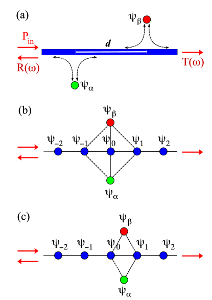
Many concepts of photonic devices employ high- optical resonators, such as micro-rings or photonic crystal cavities, side coupled to the transmission waveguide. Among them, the devices which employ several resonators have attracted a special attention because the coupling between optical resonators may lead to a variety of novel effects such as the high-order resonances with flattened passband region [1, 2, 3], the appearance of additional resonances with extremely high- factors [3], etc. One of the most interesting and promising effects that was discovered for the double-resonator photonic structure shown schematically in Fig. 1(a) is an all-optical analogue of the electromagnetically-induced transparency (EIT). We describe the resonant transmission observed for such structure as the effect of coupled-resonator-induced transparency (CRIT) [4]. It has been predicted theoretically by several research groups [4, 5, 6, 7, 8], although one can also mention the early work [9] which suggested an idea of macroscopic double-resonator optical system exhibiting the same EIT-like effect. Recently, the CRIT effect has been observed experimentally in the system of two interacting micro-resonators for the whispering-gallery modes [10] and in the integrated photonic chips employed either two micro-ring resonators [11, 12] or two photonic-crystal cavities [13]. Such CRIT devices provide an efficiently tunable ‘transparency on an optical chip’, and they are considered as a crucial step towards the development of integrated all-optical chips [14]. In particular, they can be employed for significant ( times) reduction of the threshold power for optical bistability [15].
In this paper, we study the transmission of light in several types of the resonant structures based on a photonic-crystal (PhC) waveguide side-coupled to two nearly identical PhC cavities, as shown schematically in Fig. 1(b) and Fig. 1(c). We confirm that in the case of on-site coupling of two cavities to a PhC waveguide, as shown schematically in Fig. 1(b), the CRIT effect may be observed (see also the recent experimental observation [13] of the CRIT effect in a PhC structure with on-site coupling). However, for the structure shown in Fig. 1(c), we reveal the existence of a closely related effect of coupled-resonator-induced reflection (CRIR) that manifests itself in an extremely narrow resonant reflection line whose quality factor can easily be tuned by changing one of the cavities. Specifically, the quality factor grows indefinitely when the optical properties of two coupled cavities become identical.
In a sharp contrast to the CRIT effect that can be observed in the structures with many different types of waveguides [11, 12, 13] or even for light propagating in free space with no waveguide at all [10], we reveal that the existence of the CRIR effect is determined by the discrete nature of the photonic crystal waveguide and it can be observed, therefore, in either coupled-resonator optical waveguides (CROWs) or PhC waveguides, both created by an array of coupled optical cavities. Recently, we have demonstrated a crucial importance of the discrete nature of PhC waveguides for achieving high- resonant reflection and low-threshold all-optical switching in the slow-light regime [16, 17]. We have shown that this can be achieved by employing of inter-site coupling of a single Kerr nonlinear cavity to a PhC waveguide.
Here, we extend those results further and demonstrate that employing of inter-site coupling of two cavities in the PhC waveguide structure shown schematically in Fig. 1(c), leads to the transformation of the CRIT effect into the CRIR effect. We also show that in contrast to the CRIT effect in the structures with the on-site coupling, the CRIR effect observed in the structures with the inter-site coupling survives in the slow-light regime, and thus it can be employed for a control on the slow-light propagation and switching. As an example, we demonstrate a possibility to achieve 100% all-optical switching of slow light in the nonlinear regime.
2 Coupled-resonator-induced transparency
First, we remind the basic facts about the CRIT effect assuming for definiteness that the resonant photonic structure is created by a straight dielectric waveguide and two side-coupled cavities, denoted as and and separated by the distance along waveguide, as shown schematically in Fig. 1(a).
To simplify the analysis, below we assume that any losses are absent, so that the transmission () and reflection () coefficients can be conveniently written in the form
| (1) |
where the detuning function may have a rather general frequency dependence defined by the type of the PhC waveguide-cavity structures (see, e.g., several examples in Refs. [16, 20]. The zero transmission (complete reflection) corresponds to the condition , whereas the complete transmission (vanishing reflection) corresponds to the condition . Therefore, the resonant frequencies can be conveniently found as zeros of the nominator and denominator of the auxiliary function .
For the simplest resonant structure created by a straight waveguide coupled to a single cavity (e.g., the cavity ), we can obtain [16]
| (2) |
with a resonant reflection at the frequency that almost coincides with the frequency of the localized cavity mode of an isolated cavity. The spectral width of the resonance is determined by the overlap integral between the cavity mode and the waveguide mode at the resonant frequency, rapidly decaying as the distance between the cavity and the waveguide grows.
To find the characteristic function for the waveguide structure with two cavities, we can employ a variety of methods [5, 6, 7, 8, 15], including the simplest approach based on the transfer-matrix technique [19]. A detailed analysis of the light scattering in such structures can be found in Refs. [6, 11, 18], and here we present the results for the special case when two cavities are separated by the distance , where is the waveguide dispersion relation, is integer, and the frequency is defined below. In this case, assuming that there is no direct coupling between the cavities, i.e. either the distance is sufficiently large or the cavities are coupled to the waveguide from the opposite sides, we obtain
| (3) |
with the total resonance width and the frequency of perfect transmission
| (4) |
lying in between the two frequencies, and , of the zero transmission. Importantly, these frequencies coincide with the frequencies of the localized cavity modes of the isolated cavities and .
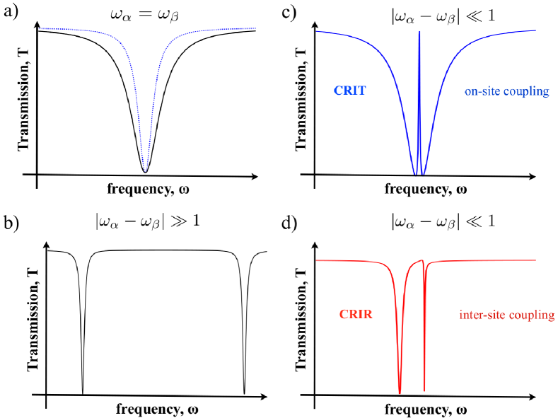
In the case when the cavities and are identical, Eq. (3) reduces to the single-cavity result (2) with a doubled resonance width, , as is illustrated in Fig. 2(a). When the cavities and are significantly different, the structure exhibits two almost uncoupled single-cavity resonances, as is illustrated in Fig. 2(b). However, introducing only a small difference between the parameters of the two cavities leads to opening an extremely narrow resonant transmission on the background of the broader reflection line, as is illustrated in Fig. 2(c). Indeed, for a small difference between the cavity parameters we assume that , and introducing notation , rewrite Eq. (3) in the vicinity of the resonant transmission frequency as with and
| (5) |
The line width of this resonance can easily be controlled by tuning the frequency difference , and the corresponding quality factor, , grows indefinitely when vanishes. As we mentioned above, this effect can be regarded as an all-optical analogue of the electromagnetically-induced transparency, and it is now often referred as the effect of coupled-resonator-induced transparency – CRIT [4].
3 Model description of photonic crystal structures
For the photonic structures based on photonic-crystal waveguides we have a new option (comparing with strip-waveguide structures) for achieving the resonant transmission by placing the cavity at different location relative to the waveguide and thus exploring the discrete nature of the structure. Recently, we have demonstrated [16, 17] that, by employing this extra degree of freedom in the waveguide-cavity geometry with one cavity, we can dramatically increase the quality factor of the resonant reflection in the slow-light regime and, accordingly, decrease the light power required for the observation of bistability in the light transmission. Here, we extend this analysis to the case of two-cavity structures and reveal new physics.
As was shown in Refs. [16, 20], the light transmission in the waveguide-cavity photonic crystal structures can be accurately modeled with the effective discrete equations for the frequency-dependent dimensionless electric field amplitudes of the cavity modes composing the waveguide, , with integer , and side-coupled cavity modes, , with . By applying this approach to the structures shown in Figs. 1(b,c), such equations can be rewritten as follows
| (6) |
Here, , where describes the waveguide dispersion and is the distance between nearest-neighboring waveguide’s cavities. Each side-coupled cavity is described by the frequency of the localized cavity mode, the dimensionless Kerr nonlinearity coefficient , and the “effective” spectral width of the single-cavity resonance (the meaning of “effective” here will be clarified in the subsequent analysis). The dimensionless coupling coefficients are assumed to be equal (after appropriate rescaling of , , and ) to either zero or ; their values will be indicated in what follows individually for each studied case. The resonance detuning function can be found by solving Eq. (3) in the way similar to that described in Refs. [16, 20].
These equations are valid in the approximation of local coupling between the cavities composing the waveguide structure which has been shown to produce qualitatively (and even semi-quantitatively) correct results [16, 20]. In the form (3), the effective discrete equations look very similar to those derived from the coupled-mode theory [21] for the case of coupled-resonator optical waveguides [22] and, therefore, our subsequent analysis can be applied to all such structures as well.
First, we analyze briefly the photonic crystal structure with two cavities, and , side-coupled to the same on-site location along PhC waveguide as shown in Fig. 1(b). The situation when only one of these cavities is coupled to the waveguide (with and , where is the Kronecker symbol) has already been studied earlier in Refs. [16, 20]. In this case the model parameters introduced in Eq. (3) are related to the parameters introduced in Eqs. (21)–(24) of Ref. [16] as , , , and . Therefore, the linear (at ) detuning function found for this case in Ref. [16] takes the form of Eq. (2) with unchanged form of and with . As one can see, is the spectral width of the resonant reflection line that would be produced by a single on-site side-coupled cavity in the case when its frequency lies at the center of the waveguide transmission band, .
In the same way, we can show that the detuning function of the on-site two-cavity structure with for both , shown in Fig. 1(b), takes the form of Eqs. (3)–(5) with unchanged forms of and , and with and . Correspondingly, this on-site two-cavity structure exhibits the same effect of coupled-resonator-induced transparency, illustrated in Fig. 2(c), as discussed in the previous section.
4 Coupled-resonator-induced reflection
Now let us analyze an alternative photonic crystal structure with two cavities, and , side-coupled to the same inter-site location along PhC waveguide as shown in Fig. 1(c). In this case, , where the upper sign in “” corresponds to the even-symmetry cavity modes, while the bottom sign corresponds to the odd-symmetry cavity modes.
The situation when only one of the cavities (say, the cavity ) is coupled to the waveguide (with , but ) has already been studied for the even-symmetry cavity modes in Refs. [16, 20]. Extending those results to the case of both even- and odd-symmetry cavity modes, the detuning parameter for the inter-site single-cavity structure can be obtained in the form
| (7) |
where the resonant reflection frequency is shifted to one or the other side from the frequency of the cavity mode, depending on its symmetry. The spectral width of this resonance line equals to at the center of waveguide pass-band, but it vanishes at one of the band edges, giving birth to extremely high-quality resonant reflection lines in the slow-light regime [16, 17].
For the problem of the light transmission in the inter-site two-cavity structure shown in Fig. 1(c), we solve Eq. (3) and obtain the detuning parameter in the form,
| (8) |
that looks qualitatively similar to Eq. (3). Moreover, the frequency of the perfect transmission is determined by the same equation for the CRIT effect (4) with . However, now the total resonance width depends on the waveguide dispersion, , at the resonance frequency leading to the same enhancement of the resonance quality factor at one of the edges of waveguide pass-band as obtained above for the inter-site one-cavity structure. More importantly, the resonant reflection frequencies,
| (9) | |||||
do not coincide with the cavity-mode frequencies and . Moreover, these two resonant reflection frequencies are always separated by a finite distance exceeding the value and, therefore, the existence of a narrow resonant transmission becomes merely impossible.
In contrast, the inter-coupling between the waveguide and two cavities in this system manifests itself in a qualitatively new effect of coupled-resonator-induced reflection: for small one of the resonant reflection frequencies moves very close to the perfect transmission frequency, , producing a narrow resonant reflection line, as is illustrated in Fig. 2(d). The frequency of this line is always close to the frequency of the cavity mode, while its spectral width is determined by the frequency difference growing indefinitely as vanishes. For a small difference between the cavity frequencies, assuming , we can estimate that the spectral width of this narrow reflection line is
| (10) | |||||
At small and lying at the center of the passing band, this spectral width almost coincides with the corresponding width (5) of the narrow resonant transmission line in the structures exhibiting the CRIT effect.
In addition to this narrow resonant reflection line, there always exists the second resonant reflection line located (at small ) at the frequency , significantly shifted from the frequency of the cavity modes. This line is characterized by the spectral width which is twice larger than the width of the corresponding single-cavity resonance [16].
It should be emphasized that despite such a qualitative difference in their spectral manifestations, both CRIT and CRIR effects have the same physical origin which can be attributed to the Fano-Feshbach resonances [24, 25] known to originate from the interaction of two or more resonances (e.g., two Fano resonances) in the overlapping regime where the spectral widths of the resonances are comparable to or larger than the frequency separation between them. In a general case, this leads to a drastic deformation of the transmission spectrum and the formation of additional resonances with sharp peaks. The Fano-Feshbach resonances are associated with a collective response of multiple interacting resonant degrees of freedom, and they have numerous evidences in quantum mechanical systems [26, 27].
For the PhC structures studied in this paper, the two resonant degrees of freedom are associated with two side-coupled cavities, which can be coupled to PhC waveguide in two different ways, illustrated in Fig. 1(b) and Fig. 1(c), with the different manifestation of the Fano-Feshbach resonance in these two cases in the form of either CRIT or CRIR effects.
5 Photonic structure exhibiting the CRIR effect
As an example of the specific structure exhibiting the CRIR effect, we consider a two-dimensional PhC composed of a triangular lattice of dielectric rods in air. The rods are made of either Si or GaAs () with the radius , where is the lattice spacing. This type of PhC has two large bandgaps for the E-polarized light (i.e. when the electric field is parallel to the rods), and we employ the first gap between the frequencies and .
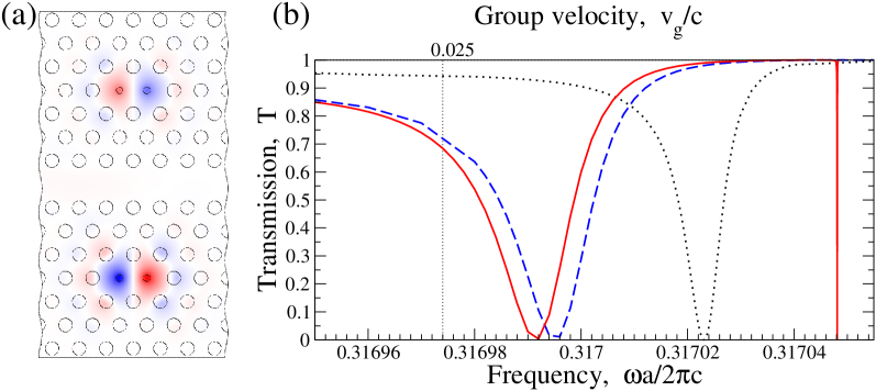
We assume that the photonic-crystal waveguide is created by removing a row of rods, while each of the cavities is created by reducing radius of two nearest rods to the value . The lines connecting defect rods in each cavity are parallel to the waveguide being separated from the waveguide by three rows of rods, as shown in Fig. 3(a). Each cavity supports two localized modes: (i) high-frequency mode with an odd symmetry, and (ii) low-frequency mode with an even symmetry. Here, we use the properties of the odd-symmetry mode which has been discussed recently for the slow-light applications [17], and, therefore, we select the bottom sign in expressions “” and “” in Eqs. (7)–(10).
First, in Fig. 3 and Fig. 4 we present numerically accurate results for this structure obtained by employing the Wannier functions approach with eleven maximally localized Wannier functions, in the way outlined in Ref. [23]. To emphasize that the CRIR effect in such a structure survives also in the slow-light regime, we shift the resonance to a vicinity of the passing band edge by choosing . In Fig. 3(a) we plot the corresponding distributions of the electric field at the low-frequency resonance. Figure 3(b) shows the transmission spectra for three structures: with only a single side-coupled cavity (dotted line), with two identical side-coupled cavities (dashed line), and with two slightly different side-coupled cavities (solid line). As can be seen, the results of these full-scale calculations are in a very good agreement with our analysis based on the approximate discrete model and presented in Sec. 4.
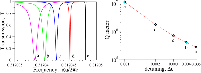
In Fig. 4 we plot the transmission spectra of the narrow resonant reflection line and the corresponding resonance quality factors for several values of detuning between the dielectric constants of two cavities. As is seen, the indefinite growing of the resonance quality factor with vanishing of this detuning is in full qualitative agreement with the model prediction provided by Eq. (10).
6 Nonlinear transmission and all-optical switching
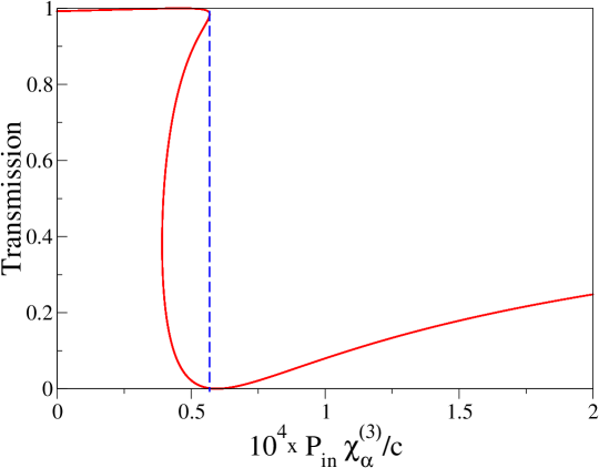
In the nonlinear regime, the CRIR structures described here demonstrate low-threshold bistable transmission of light due to the ultra-high factor of the asymmetric Fano-Feshbach resonance. For specific example, in Fig. 5 we present the results for the nonlinear transmission of the waveguide-two-cavities structure for the parameters used in Fig. 3 assuming that only one of the cavities is made nonlinear. In this case, choosing the frequency close to the asymmetric resonance allows achieving a complete 100 switching in the regime of the slow-light propagation.
We would like to mention that, to demonstrate the efficiency of the approximations employed in this work, the results for the nonlinear transmission shown in Fig. 5 are obtained by employing the approximate discrete model based on Eq. (3) with the model parameters calculated with the the Wannier function approach [23], in contrast to the numerical results presented in Fig. 3–Fig. 4. Using eleven maximally localized Wannier functions, we obtain the following expansions,
| (11) |
and
| (12) |
while the waveguide dispersion in the slow-light regime can be approximated as
| (13) |
Thus, one of our major finding is that, in a sharp contrast to the CRIT effect, this novel CRIR resonant effect survives also in the slow-light regime and, due to its asymmetric line shape, it allows achieving a 100% all-optical switching of slow light in the nonlinear regime. Currently, the slow-light applications of optical structures based on photonic crystals attract a rapidly growing attention due to the recently achieved experimental success in the observation of slow-light propagation [28, 29, 30, 31]. However, many of the device concepts suggested so far in the physics of photonic crystals cannot be extended to the slow-light regime, and it is important to reveal and analyze novel types of the design concepts which would allow to perform useful operations such as all-optical switching and routing with low group velocities [32, 33, 16, 17]. We therefore believe that the CRIR effect described in this work may be especially useful for elaborated control of slow light, however more extensive studies are beyond the scope of this paper.
7 Conclusions
We have analyzed the resonant transmission of light in a coupled-resonator optical waveguide interacting with two nearly identical cavities, paying a particular attention to differences between the on-site and inter-site locations of the cavities relative to the waveguide. When two cavities are strongly detuned and associated resonances are well separated [see Fig. 2(b)], both types of photonic-crystal structures are characterized by the similar transmission curves with two distinct Fano resonances. However, when two cavities are only slightly detuned and, therefore, the associated resonances strongly overlap, the on-site and inter-site structures produce quantitatively different transmission curves. Specifically, the on-site geometry shown in Fig. 1(b) may lead to the CRIT effect with a sharp symmetric resonant transmission line [see Fig. 2(c)], while the inter-site geometry shown in Fig. 1(c) may lead to the CRIR effect with a sharp and asymmetric resonant reflection line [see Fig. 2(d)]. The new CRIR transmission we have described here is characterized by a very high and easily tunable quality factor of the reflection line, and this effect differs sharply from the CRIT effect being an all-optical analogue of the electromagnetically-induced transparency demonstrated recently for the structures based on micro-ring resonators. We have demonstrated that the CRIR effect survives also in the slow-light regime and, due to its asymmetric line shape, it allows achieving a 100% all-optical switching of slow light in the nonlinear regime.
Acknowledgements
This work has been supported by the Australian Research Council through the Discovery and Center of Excellence research projects.