Giant Carrier Mobility in Single Crystals of FeSb2
Abstract
We report the giant carrier mobility in single crystals of FeSb2. Nonlinear field dependence of Hall resistivity is well described with the two-carrier model. Maximum mobility values in high mobility band reach cm2/Vs at 8 K, and are cm2/Vs at the room temperature. Our results point to a class of materials with promising potential for applications in solid state electronics.
FeSb2 is a narrow band nearly magnetic or Kondo semiconductor with 3d ions.Petrovic1 It crystallizes in Pnnm orthorhombic structure and shows pronounced anisotropy in transport properties. Along the high conductivity axis, metal-insulator transition onsets in the vicinity of T K, while the electronic transport along two other axes is semiconducting for temperatures up to 350 K.Perucchi ,Petrovic2 Moreover, the doping strongly affects the properties of FeSb2.RongweiDop1 ,RongweiDop2 For example, colossal magnetoresistance (CMR) of the same order of magnitude as in manganite oxides and multiband transport properties are observed in Fe1-xCoxSb2 (x = 0 - 0.5).Salamon ,Rongwei In this work, we report high Hall mobility in FeSb2 that reaches 77 352 547 cmVs, the value comparable to that of the Si/SiGe heterostructures.Ismail
Single crystals of FeSb2 were grown from Sb flux.Petrovic2 ,Rongwei Crystals were polished into rectangular bars and Pt wires were attached using Epotek H20E silver epoxy. The electrical and Hall resistivity were measured in Quantum Design PPMS instrument using four wire and five wire configuration for AC measurements, respectively. The current was applied along high conductivity -axis. The magnetic field was applied successively in and directions and the transverse voltage was picked up in the orthogonal [110] direction. One half of the transverse voltage difference for field in two directions was taken as the Hall voltage. The magnetization () was measured in Quantum Design MPMS in the applied magnetic field of H = 1000 Oe along three principal crystallographic axes. Polycrystalline magnetization was calculated as the average of measured along the principal axes.
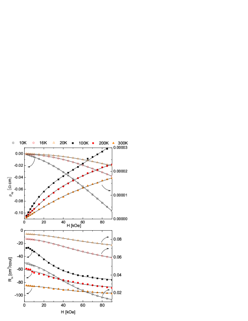
The magnetic field dependence of the Hall resistivity () is shown in Fig. 1(a). A nonlinear field dependence of for up to 90 kOe is evident. This result commonly indicates an anomalous Hall effect. As in the case of Fe1-xCoxSb2, we discard this possibility by comparing experimental curves with the those obtained by fitting data to , where R0 and RS are the normal and spontaneous Hall constant and is the experimentally obtained sample magnetization.Rongwei Nevertheless, the nonlinear magnetic field dependence of is often observed in multi-carrier materials, such as semiconducting heterostruture devices, InP pHEMT device, and MnAs.Della ,Berry Therefore, our data implies that the nontrivial dependence of originates from the presence of different carriers. We now proceed to the analysis of the data in the multi-carrier scenario.
In a two-carrier model, the Hall coefficient can be expressed in the following form
| (1) | |||||
Here is the zero field resistivity, the mobility of ith carrier, and the factor.JSKim We point out that the term “carrier” is defined as a set of carriers having the same mobility. Therefore, one carrier is associated with only one energy and/or one degenerate energy level. It is different from the conventional electron or hole carriers, that may relate to a continuous energy band. An excellent agreement of the RH field dependence with the two-carrier model Eq. 1 is illustrated in Fig. 1(b). Thus, the mobility and concentration of individual carriers can be extracted.
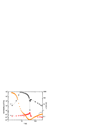
The temperature dependence of the mobility is shown in Fig. 2. It was generated from a large number of Hall resistivity isotherms. At room temperature two types of charge carriers, high mobility ( cm2/Vs) and low mobility ( cm2/Vs) ones, are present. The low mobility carriers display a relatively weak temperature dependence. The magnitude of slightly increases only in the vicinity of T 40 K, temperature of metal to insulator crossover. On the other hand, the high mobility component, , displays a significant temperature dependence. As decreases from 300 K, its value increases from (300K)=110 2cm2/Vs to reach a remarkably high maximum value of (8K)=77352 547 cm2/Vs at T = 8 K. Below T = 8 K, decreases and at T = 1.8 K, lowest investigated, it reaches the value comparable to the room temperature one. In contrast to the low mobility carriers, the sign of changes from negative to positive in the vicinity of T∗. That is to say the conduction changes from the electron to hole-like. Mobility and carrier concentration changes at T∗ are rather sharp in comparison with crossover – like feature in resistivity and magnetic susceptibility. Simultaneous increase of mobility in low mobility band and decrease of mobility in high mobility band as well as changes from hole to electron conduction in large mobility band around T∗ could contribute to somewhat broad resistivity transition. Large increase in thermally induced paramagnetic moment occurs above T∗ possibly due to indirect energy gap.
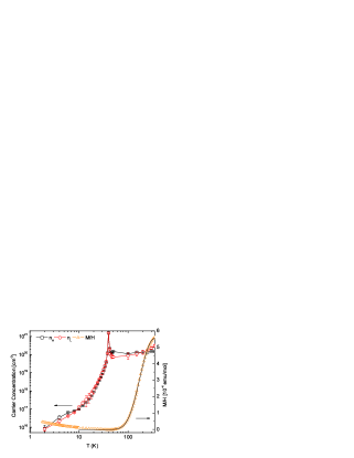
The temperature dependence of the carrier concentrations corresponding to and is shown in Fig. 3. Large increase of magnetic susceptibility above T∗ coincides with small changes in carrier concentration above 100 K. There is little change in M/H below T∗. It appears therefore that significant reduction in carrier concentration below T∗ predominantly influences conductivity (Fig. 2). This may indicate larger (direct) energy gap in M/H and smaller (indirect) energy gap for electronic transport, as observed in FeSi.Paschen In the metallic region of conductivity, from room temperature down to T∗, concentrations of both low, (electron-like above T∗), and high, (hole-like above T∗), mobility carrier components slowly decrease. Below T∗, both and decrease by approximately five orders of magnitude. The peak in the coincides with the sign change of mobility at the T∗. This suggests that the T∗ is related to the intrinsic reconstruction of the electronic properties of FeSb2 at the metal to insulator crossover. This observation, together with the fact that the concentration of low mobility electron carriers increases by one order of magnitude at T∗, may imply that above T∗ the Fermi level is situated in a band with a larger density of states. This interpretation of FeSb2 is consistent with the narrow band small gap Kondo description, based on a model of two narrow bands at the density of states of width W separated by Eg=2.Jaccarino ,Mandrus This model is supported by the LDA+U band structure calculation of FeSbLukoyanov It appears though that metal insulator crossover at T∗ has large effect on the high mobility carrier system. As the sample is cooled down to , the electrical resistivity increases more than four orders of magnitude from its lowest value at T∗. The change of slope of at K, as well as its pronounced decrease below K, is reflected in corresponding changes in below T∗. This may imply successive destruction of several quasi - one dimensional pieces of the Fermi surface below T∗, as reported, for example, in -Mo4O11.Hill The carrier concentrations and their temperature dependencies are almost identical whereas mobilities differ by many orders of magnitude. In the standard paradigm of Kondo InsulatorsAeppli hybridization involves one flat band and one dispersive conduction electron band. As opposed to FeSi, hybridization with Sb-p orbitals in FeSb2 could create multiple sheets at the Fermi surface with large mobility difference.
Conduction properties of marcasite antimonides are influenced by distortion of edge-sharing Fe-Sb octahedra. The Fe-Sb-Fe bond angle governs the dxy orbitals’ overlap, extending along the octahedral edges, and consequently magnetic and electronic properties of FeSb2.Petrovic1 ,Goodenough Within the Kondo insulator framework, our results imply that the hybridization in this multicarrier system is rather heterogenous and may involve only one electronic subsystem, whereas the other is characterized by much lower effective mass and consequently higher mobility. Orbital - selective probes and high resolution local structural probes would be very useful to shed more light to this problem. Synthesis of the iron diantimonide thin films may enable fabrication of a variety of devices, that exploit high mobility carrier channels. Moreover, due to low resistivity and high mobility of carriers this material may be of interest in photovoltaics industry, providing that the energy gap proves to be tunable.
In conclusion, we have demonstrated giant Hall mobility in correlated electron or ”Kondo” semiconductor FeSb2. The mobility is remarkably large, comparable to the high mobility heterostructures and semiconductor devices. The observed magnetic field dependence of Hall coefficient can be described by a two-carrier model. The presence of the metal - insulator crossover temperature T∗ and quenching of temperature induced paramagnetic moment is intimately connected with changes in Hall mobility and carrier concentration of individual carrier systems. Our results point to a class of materials showing promise for application in high-speed electronic devices.
This work was carried out at the Brookhaven National Laboratory which is operated for the U.S. Department of Energy by Brookhaven Science Associates (DE-Ac02-98CH10886).
References
- (1) C. Petrovic, Y. Lee, T. Vogt, N. Dj. Lazarov, S. L. Bud’ko, and P. C. Canfield, Phys. Rev. B 72, 045103 (2005)
- (2) A. Perucchi, L. Degiorgi, Rongwei Hu, C. Petrovic and V. F. Mitrovic, European Physical Journal B 54, 175 (2006)
- (3) C. Petrovic, J. W. Kim, S. L. Bud’ko, A. I. Goldman, and P. C. Canfield, Phys. Rev. B 67, 155205 (2003)
- (4) Rongwei Hu, R. P. Hermann, F. Grandjean, Y. Lee, J. B. Warren, V. F. Mitrović, and C. Petrovic, Phys. Rev. B 76, 224422 (2007)
- (5) Rongwei Hu, V. F. Mitrović, and C. Petrovic, Phys. Rev. B 76, 115105 (2007).
- (6) Myron B. Salamon and Marcelo Jaime, Rev. Mod. Phys. 73, 583 (2001)
- (7) Rongwei Hu, K. J. Thomas, Y. Lee, T. Vogt, E. S. Choi, V. F. Mitrovic, R. P. Hermann, F. Grandjean, P. C. Canfield, J. W. Kim, A. I. Goldman, and C. Petrovic, Phys. Rev. B 77, 085212 (2008)
- (8) K. Ismail, M. Arafa, K. L. Saenger, J. O. Chu, and B. S. Meyerson, Appl. Phys. Lett. 66, 1077 (1995)
- (9) J. M. Della, L. Faraonea, L. S. Tanb, A. Ramanb, S. J. Chuab, D. S Holmesc, J. R. Lindemuthc, J. Antoszewskia, and J. R. Meyerd, Materials Science and Engineering B, 44, 65 (1997)
- (10) J. J. Berry, S. J. Potashnik, S. H. Chun, K. C. Ku, P. Schiffer, and N. Samarth, Phys. Rev. B, 64, 052408 (2001)
- (11) J.S. Kim, J. App. Phys. 86, 3187 (1999)
- (12) S. Paschen, E. Felder, M. A. Chernikov, L. Degiorgi, H. Schwer, H. R. Ott, D. P. Young, J. L. Sarrao, and Z. Fisk, Phys. Rev. B 56, 12916 (1997)
- (13) V. Jaccarino, G. K. Wertheim, J. H. Wernick, L. R. Walker, and Sigurds Arajs, Phys. Rev. 160, 476 (1967)
- (14) D. Mandrus, J. L. Sarrao, A. Migliori, J. D. Thompson, and Z. Fisk, Phys. Rev. B 51, 4763 (1995 )
- (15) A. V. Lukoyanov, V.V. Mazurenko, V.I. Anisimov, M. Sigrist and T.M. Rice, European Physical Journal B 53, 205 (2006)
- (16) S. Hill, S. Valfells, S. Uji, J. S. Brooks, G. J. Athas, P. S. Sandhu, J. Sarrao, J. Fisk, H. Aoki and T. Terashima, Phys. Rev. B 55, 2018 (1997)
- (17) G. Aeppli and Z. Fisk, Comments Condens. Matter Phys. 16, 155 (1992)
- (18) J. B. Goodenough, J. Solid State Chem. 5, 144 (1972)