Methods for linear optical quantum Fredkin gate

Yan-Xiao Gong yxgong@mail.ustc.edu.cn Centre for Quantum Computer Technology, Department of Physics, University of Queensland, St Lucia 4072, Australia Key Laboratory of Quantum Information, University of Science and Technology of China, CAS, Hefei, 230026, People’s Republic of China    Guang-Can Guo Key Laboratory of Quantum Information, University of Science and Technology of China, CAS, Hefei, 230026, People’s Republic of China    Timothy C. Ralph Centre for Quantum Computer Technology, Department of Physics, University of Queensland, St Lucia 4072, Australia
Abstract

We consider the realization of quantum Fredkin gate with only linear optics and single photons. First we construct a heralded Fredkin gate using four heralded controlled-not (CNOT) gates. Then we simplify this method to a post-selected one utilizing only two CNOT gates. We also give a possible realization of this method which is feasible with current experimental technology. Another post-selected scheme requires time entanglement of the input photons but needs no ancillary photons.

pacs:
03.67.Lx, 42.50.Dv

I Introduction

Quantum computing Nielsen and Chuang (2000), due to its potential to solve problems far beyond classical computers, has attracted great attention in the last years. Many physical systems have been considered for a quantum computer Spiller et al. (2005). One promising system is to use single photons, showing benefits such as low decoherence and easy single-qubit manipulation. However, such system suffers a major disadvantage — the lack of interaction between individual photon qubits, which is needed for implementing non-trivial multi-qubit gates. Surprisingly, Knill, Laflamme, and Milburn have demonstrated that scalable quantum computing was possible using linear optical elements, single photons and photon detection Knill et al. (2001). After that, lots of researches have been devoted to linear optical quantum computing (LOQC) Kok et al. (2007).

Here we focus on the implementation of linear optical Fredkin gate Fredkin and Toffoli (1982), which plays an important role in both classical computing and quantum computing Nielsen and Chuang (2000). The Fredkin gate is also known as a three-qubit controlled-swap gate, that is, if the control qubit is in state |1ket1|1\rangle, the two target qubits swap their states and otherwise, they remain in their initial states if the control qubit is in state |0ket0|0\rangle. In the context of universal quantum computer, multi-qubit gates are usually thought to be built by a combination of single- and two-qubit gates. Smolin and DiVincenzo have shown that five two-qubit gates are sufficient to implement the Fredkin gate Smolin and DiVincenzo (1996). Assuming that the two-qubit gate, as the controlled-not (CNOT) gate in Pittman et al. (2001), can be implemented using two ancillary photons with success probability of 1/4141/4, their gate needs ten ancillary photons and the total success probability is 451.0×10³superscript451.0superscript1034^{-5}\approx 1.0\times 10^{-3}. It is too difficult and not possible with current experimental technology. Recently, another scheme was proposed in Fiurášek (2006) by simulating the Kerr medium in Milburn’s optical Fredkin gate Milburn (1989) with linear optical elements. It needs only six ancillary photons with the success probability 4.1×1034.1superscript1034.1\times 10^{-3}.

Recently, the complexity of the Toffoli gate was highly reduced and the success probability was improved Ralph et al. (2007). In this paper, we wish to see if a similar effect can be achieved by applying those techniques to the Fredkin gate. We propose some methods for implementing the Fredkin gate with linear optics and single photons. The qubits in our schemes are all encoded in polarization states of single photons, so that |0|Hket0ket𝐻\mbox{$|0\rangle$}\equiv\mbox{$|H\rangle$} and |1|Vket1ket𝑉\mbox{$|1\rangle$}\equiv\mbox{$|V\rangle$}, where |Hket𝐻|H\rangle (|Vket𝑉|V\rangle) denotes the horizontal (vertical) polarization state. The rest of the paper is organized as follows. In the next section we propose a heralded Fredkin gate using four heralded CNOT gates. In Section III we give a post-selected Fredkin gate, i.e., working in the coincidence basis, and we also present a possible optical realization which is feasible with existing technology. In Section IV we replace the four heralded CNOT gates in the heralded scheme with four post-selected CNOT gates assisted by time entanglement but without ancillary photons. We conclude in Section V.

II Heralded Fredkin gate

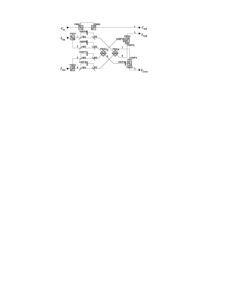
Our heralded Fredkin gate is built up from four CNOT gates. The schematic structure is shown in Fig. 1. To show how the scheme works, we consider an arbitrary input state written as,

a1|Hcin|Ht1in|Ht2in+a2|Hcin|Ht1in|Vt2insubscript𝑎1subscriptket𝐻subscript𝑐insubscriptket𝐻subscript𝑡1insubscriptket𝐻subscript𝑡2insubscript𝑎2subscriptket𝐻subscript𝑐insubscriptket𝐻subscript𝑡1insubscriptket𝑉subscript𝑡2in\displaystyle a_{1}\mbox{$|H\rangle$}_{c_{\text{in}}}\mbox{$|H\rangle$}_{t_{1\text{in}}}\mbox{$|H\rangle$}_{t_{2\text{in}}}+a_{2}\mbox{$|H\rangle$}_{c_{\text{in}}}\mbox{$|H\rangle$}_{t_{1\text{in}}}\mbox{$|V\rangle$}_{t_{2\text{in}}}
+\displaystyle+ a3|Hcin|Vt1in|Ht2in+a4|Hcin|Vt1in|Vt2insubscript𝑎3subscriptket𝐻subscript𝑐insubscriptket𝑉subscript𝑡1insubscriptket𝐻subscript𝑡2insubscript𝑎4subscriptket𝐻subscript𝑐insubscriptket𝑉subscript𝑡1insubscriptket𝑉subscript𝑡2in\displaystyle a_{3}\mbox{$|H\rangle$}_{c_{\text{in}}}\mbox{$|V\rangle$}_{t_{1\text{in}}}\mbox{$|H\rangle$}_{t_{2\text{in}}}+a_{4}\mbox{$|H\rangle$}_{c_{\text{in}}}\mbox{$|V\rangle$}_{t_{1\text{in}}}\mbox{$|V\rangle$}_{t_{2\text{in}}}
+\displaystyle+ a5|Vcin|Ht1in|Ht2in+a6|Vcin|Ht1in|Vt2insubscript𝑎5subscriptket𝑉subscript𝑐insubscriptket𝐻subscript𝑡1insubscriptket𝐻subscript𝑡2insubscript𝑎6subscriptket𝑉subscript𝑐insubscriptket𝐻subscript𝑡1insubscriptket𝑉subscript𝑡2in\displaystyle a_{5}\mbox{$|V\rangle$}_{c_{\text{in}}}\mbox{$|H\rangle$}_{t_{1\text{in}}}\mbox{$|H\rangle$}_{t_{2\text{in}}}+a_{6}\mbox{$|V\rangle$}_{c_{\text{in}}}\mbox{$|H\rangle$}_{t_{1\text{in}}}\mbox{$|V\rangle$}_{t_{2\text{in}}}
+\displaystyle+ a7|Vcin|Vt1in|Ht2in+a8|Vcin|Vt1in|Vt2in,subscript𝑎7subscriptket𝑉subscript𝑐insubscriptket𝑉subscript𝑡1insubscriptket𝐻subscript𝑡2insubscript𝑎8subscriptket𝑉subscript𝑐insubscriptket𝑉subscript𝑡1insubscriptket𝑉subscript𝑡2in\displaystyle a_{7}\mbox{$|V\rangle$}_{c_{\text{in}}}\mbox{$|V\rangle$}_{t_{1\text{in}}}\mbox{$|H\rangle$}_{t_{2\text{in}}}+a_{8}\mbox{$|V\rangle$}_{c_{\text{in}}}\mbox{$|V\rangle$}_{t_{1\text{in}}}\mbox{$|V\rangle$}_{t_{2\text{in}}}, (1)

where ai(i=1,2,,8)subscript𝑎𝑖𝑖128a_{i}(i=1,2,\dots,8) is an arbitrary complex number satisfying normalization condition.

Refer to caption
Figure 1: Schematic of the heralded linear optical Fredkin gate comprising four heralded CNOT gates. Lowercase letters and numbers label the beams. The input control qubit is in beam cinsubscript𝑐inc_{\text{in}} and the two input target qubits are in beams t1insubscript𝑡1int_{1\text{in}} and t2insubscript𝑡2int_{2\text{in}}. Polarizing beam splitters (PBS) transmit horizontally polarized photons and reflect vertically polarized photons. Half-wave plates HWP1 and HWP3 are oriented at 67.5superscript67.567.5^{\circ}. HWP2 and HWP4 are set to 22.5superscript22.522.5^{\circ}. The gate succeeds if the two photon number resolving detectors D1 and D2 detect no photons. The output control and target states lie in modes c𝑐c, t1subscript𝑡1t_{1} and t2subscript𝑡2t_{2}.

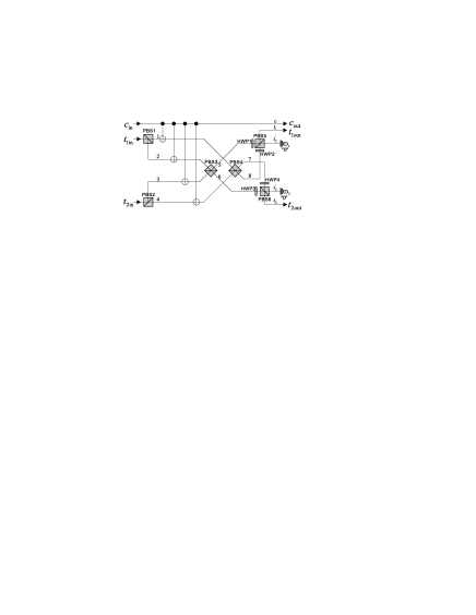
First the polarizing beam splitter PBS1 (PBS2) transmits the horizontally polarized photons to beam 1 (4) and vertically polarized photons to beam 2 (3). Then the photons in each of the beams 1, 2, 3, and 4 suffer a CNOT gate controlled by the control state. Therefore, the input state becomes

a1|Hc|H1|H4+a2|Hc|H1|V3+a3|Hc|V2|H4subscript𝑎1subscriptket𝐻𝑐subscriptket𝐻1subscriptket𝐻4subscript𝑎2subscriptket𝐻𝑐subscriptket𝐻1subscriptket𝑉3subscript𝑎3subscriptket𝐻𝑐subscriptket𝑉2subscriptket𝐻4\displaystyle a_{1}\mbox{$|H\rangle$}_{c}\mbox{$|H\rangle$}_{1}\mbox{$|H\rangle$}_{4}+a_{2}\mbox{$|H\rangle$}_{c}\mbox{$|H\rangle$}_{1}\mbox{$|V\rangle$}_{3}+a_{3}\mbox{$|H\rangle$}_{c}\mbox{$|V\rangle$}_{2}\mbox{$|H\rangle$}_{4}
+\displaystyle+ a4|Hc|V2|V3+a5|Vc|V1|V4+a6|Vc|V1|H3subscript𝑎4subscriptket𝐻𝑐subscriptket𝑉2subscriptket𝑉3subscript𝑎5subscriptket𝑉𝑐subscriptket𝑉1subscriptket𝑉4subscript𝑎6subscriptket𝑉𝑐subscriptket𝑉1subscriptket𝐻3\displaystyle a_{4}\mbox{$|H\rangle$}_{c}\mbox{$|V\rangle$}_{2}\mbox{$|V\rangle$}_{3}+a_{5}\mbox{$|V\rangle$}_{c}\mbox{$|V\rangle$}_{1}\mbox{$|V\rangle$}_{4}+a_{6}\mbox{$|V\rangle$}_{c}\mbox{$|V\rangle$}_{1}\mbox{$|H\rangle$}_{3}
+\displaystyle+ a7|Vc|H2|V4+a8|Vc|H2|H3.subscript𝑎7subscriptket𝑉𝑐subscriptket𝐻2subscriptket𝑉4subscript𝑎8subscriptket𝑉𝑐subscriptket𝐻2subscriptket𝐻3\displaystyle a_{7}\mbox{$|V\rangle$}_{c}\mbox{$|H\rangle$}_{2}\mbox{$|V\rangle$}_{4}+a_{8}\mbox{$|V\rangle$}_{c}\mbox{$|H\rangle$}_{2}\mbox{$|H\rangle$}_{3}. (2)

Next the photons in modes 2 (1) and 3 (4) are mixed at PBS3 (PBS4), followed by half-wave plates (HWP). Of these, HWP1 and HWP3 oriented at 67.5superscript67.567.5^{\circ} induce the transformations,

|Hket𝐻absent\displaystyle\mbox{$|H\rangle$}\rightarrow 12(|H+|V),12ket𝐻ket𝑉\displaystyle\frac{1}{\sqrt{2}}\left(-\mbox{$|H\rangle$}+\mbox{$|V\rangle$}\right), (3)
|Vket𝑉absent\displaystyle\mbox{$|V\rangle$}\rightarrow 12(|H+|V),12ket𝐻ket𝑉\displaystyle\frac{1}{\sqrt{2}}\left(\mbox{$|H\rangle$}+\mbox{$|V\rangle$}\right), (4)

while HWP2 and HWP4 set to 22.5superscript22.522.5^{\circ} result in,

|Hket𝐻absent\displaystyle\mbox{$|H\rangle$}\rightarrow 12(|H+|V),12ket𝐻ket𝑉\displaystyle\frac{1}{\sqrt{2}}\left(\mbox{$|H\rangle$}+\mbox{$|V\rangle$}\right), (5)
|Vket𝑉absent\displaystyle\mbox{$|V\rangle$}\rightarrow 12(|H|V).12ket𝐻ket𝑉\displaystyle\frac{1}{\sqrt{2}}\left(\mbox{$|H\rangle$}-\mbox{$|V\rangle$}\right). (6)

Finally, PBS5 (PBS6) combines the photons in modes 5 (4) and 8 (7). Thus, conditioned on a simultaneous zero detection in each of the modes t1superscriptsubscript𝑡1t_{1}^{\prime} and t2superscriptsubscript𝑡2t_{2}^{\prime} we can obtain the successful output state in modes c𝑐c, t1subscript𝑡1t_{1} and t2subscript𝑡2t_{2},

a1|Hc|Ht1|Ht2+a2|Hc|Ht1|Vt2subscript𝑎1subscriptket𝐻𝑐subscriptket𝐻subscript𝑡1subscriptket𝐻subscript𝑡2subscript𝑎2subscriptket𝐻𝑐subscriptket𝐻subscript𝑡1subscriptket𝑉subscript𝑡2\displaystyle a_{1}\mbox{$|H\rangle$}_{c}\mbox{$|H\rangle$}_{t_{1}}\mbox{$|H\rangle$}_{t_{2}}+a_{2}\mbox{$|H\rangle$}_{c}\mbox{$|H\rangle$}_{t_{1}}\mbox{$|V\rangle$}_{t_{2}}
+\displaystyle+ a3|Hc|Vt1|Ht2+a4|Hc|Vt1|Vt2subscript𝑎3subscriptket𝐻𝑐subscriptket𝑉subscript𝑡1subscriptket𝐻subscript𝑡2subscript𝑎4subscriptket𝐻𝑐subscriptket𝑉subscript𝑡1subscriptket𝑉subscript𝑡2\displaystyle a_{3}\mbox{$|H\rangle$}_{c}\mbox{$|V\rangle$}_{t_{1}}\mbox{$|H\rangle$}_{t_{2}}+a_{4}\mbox{$|H\rangle$}_{c}\mbox{$|V\rangle$}_{t_{1}}\mbox{$|V\rangle$}_{t_{2}}
+\displaystyle+ a5|Vc|Ht1|Ht2+a6|Vc|Vt1|Ht2subscript𝑎5subscriptket𝑉𝑐subscriptket𝐻subscript𝑡1subscriptket𝐻subscript𝑡2subscript𝑎6subscriptket𝑉𝑐subscriptket𝑉subscript𝑡1subscriptket𝐻subscript𝑡2\displaystyle a_{5}\mbox{$|V\rangle$}_{c}\mbox{$|H\rangle$}_{t_{1}}\mbox{$|H\rangle$}_{t_{2}}+a_{6}\mbox{$|V\rangle$}_{c}\mbox{$|V\rangle$}_{t_{1}}\mbox{$|H\rangle$}_{t_{2}}
+\displaystyle+ a7|Vc|Ht1|Vt2+a8|Vc|Vt1|Vt2.subscript𝑎7subscriptket𝑉𝑐subscriptket𝐻subscript𝑡1subscriptket𝑉subscript𝑡2subscript𝑎8subscriptket𝑉𝑐subscriptket𝑉subscript𝑡1subscriptket𝑉subscript𝑡2\displaystyle a_{7}\mbox{$|V\rangle$}_{c}\mbox{$|H\rangle$}_{t_{1}}\mbox{$|V\rangle$}_{t_{2}}+a_{8}\mbox{$|V\rangle$}_{c}\mbox{$|V\rangle$}_{t_{1}}\mbox{$|V\rangle$}_{t_{2}}. (7)

If we use the heralded CNOT gate proposed by Pittman et al. Pittman et al. (2001), we need eight ancillary photons and the success probability is 451.0×10³superscript451.0superscript1034^{-5}\approx 1.0\times 10^{-3}. Compared with the scheme by Smolin and DiVincenzo Smolin and DiVincenzo (1996), our scheme has the same success probability but needs less ancillary photons. However, our scheme is not as good as Fiurášek’s scheme Fiurášek (2006). Furthermore, as we shall see, our scheme can be simplified to a post-selected gate which may be realized with existing experimental technology.

III Post-selected Fredkin gate using two CNOT gates

We now consider the construction of a post-selected gate. By this we mean that a gate succeeds conditioned on simultaneous successful detection of exact one photon for each qubit, so-called coincidence detection. Fig. 2 is the schematic of a post-selected Fredkin gate. Comparing this scheme with the heralded one shown in Fig. 1, we can see that the simplification is replacing the two CNOT gates implementing on the photons in beams 3 and 4 controlled by the photon in beam c𝑐c by HWP5 (67.5superscript67.567.5^{\circ}) and HWP6 (22.5superscript22.522.5^{\circ}) with the transformations given by Eqs. (4) and (5), respectively.

Refer to caption
Figure 2: Schematic of the post-selected linear optical Fredkin gate using two controlled-not (CNOT) gates. Lowercase letters and numbers label the beams. The control and two target qubits are input in beams cinsubscript𝑐inc_{\text{in}}, t1insubscript𝑡1int_{1\text{in}} and t2insubscript𝑡2int_{2\text{in}}. Polarizing beam splitters (PBS) transmit horizontally polarized photons and reflect vertically polarized photons. Half-wave plates HWP1, HWP3 and HWP5 are oriented at 67.5superscript67.567.5^{\circ}. HWP2, HWP4 and HWP6 are set to 22.5superscript22.522.5^{\circ}. This gate succeeds conditioned on exact one photon in each of the output beams c𝑐c, t1subscript𝑡1t_{1} and t2subscript𝑡2t_{2}.

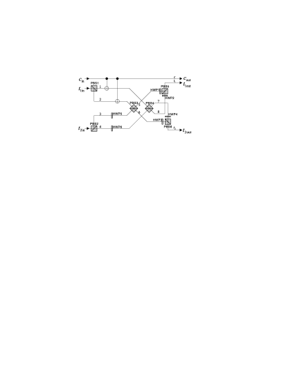
Therefore, for the input state given by Eq. (II), the state before PBS3 and PBS4 is

(a1|Hc|H1+a3|Hc|V2+a5|Vc|V1+a7|Vc|H2)subscript𝑎1subscriptket𝐻𝑐subscriptket𝐻1subscript𝑎3subscriptket𝐻𝑐subscriptket𝑉2subscript𝑎5subscriptket𝑉𝑐subscriptket𝑉1subscript𝑎7subscriptket𝑉𝑐subscriptket𝐻2\displaystyle\left(a_{1}\mbox{$|H\rangle$}_{c}\mbox{$|H\rangle$}_{1}+a_{3}\mbox{$|H\rangle$}_{c}\mbox{$|V\rangle$}_{2}+a_{5}\mbox{$|V\rangle$}_{c}\mbox{$|V\rangle$}_{1}+a_{7}\mbox{$|V\rangle$}_{c}\mbox{$|H\rangle$}_{2}\right)
12(|H4+|V4)+(a2|Hc|H1+a4|Hc|V2\displaystyle\otimes\frac{1}{\sqrt{2}}\left(\mbox{$|H\rangle$}_{4}+\mbox{$|V\rangle$}_{4}\right)+\left(a_{2}\mbox{$|H\rangle$}_{c}\mbox{$|H\rangle$}_{1}+a_{4}\mbox{$|H\rangle$}_{c}\mbox{$|V\rangle$}_{2}\right.\qquad\
+a6|Vc|V1+a8|Vc|H2)12(|H3+|V3).\displaystyle\left.+a_{6}\mbox{$|V\rangle$}_{c}\mbox{$|V\rangle$}_{1}+a_{8}\mbox{$|V\rangle$}_{c}\mbox{$|H\rangle$}_{2}\right)\otimes\frac{1}{\sqrt{2}}\left(\mbox{$|H\rangle$}_{3}+\mbox{$|V\rangle$}_{3}\right). (8)

Then through the analogy analysis in Section II and in the case of coincidence detection of the output modes c𝑐c, t1subscript𝑡1t_{1} and t2subscript𝑡2t_{2}, we can obtain the success output state the same as Eq. (II).

Refer to caption
Figure 3: Optical realization of a post-selected Fredkin gate. Lowercase letters and numbers label the beams. Photons in beams cinsubscript𝑐inc_{\text{in}}, t1insubscript𝑡1int_{1\text{in}} and t2insubscript𝑡2int_{2\text{in}} are the control and two target qubits. Polarizing beam splitters (PBS) transmit horizontally polarized (|Hket𝐻|H\rangle) photons and reflect vertically polarized (|Vket𝑉|V\rangle) photons. A heralded controlled-not (CNOT) gate proposed in Pittman et al. (2001) lies in the dotted box. EPR is an ancillary Bell state source. RPBS, transmitting 45superscript4545^{\circ} polarized (|+ket|+\rangle) photons and reflecting 45superscript45-45^{\circ} polarized (|Vket𝑉|V\rangle) photons, can be realized by inserting one half-wave plate (HWP) oriented at 22.5superscript22.522.5^{\circ} in each of the two inputs and two outputs of a PBS. D1 and D2 are photon detectors detecting +/+/- basis and H/V𝐻𝑉H/V basis, respectively. A post-selected CNOT gate suggested in Ralph et al. (2002) is enclosed by the dashed box. Beam splitters are represented as black lines with their reflectivity indicated aside and dotted line indicates the surface from which a sign change occurs upon reflection. HWP1, HWP3 and HWP5 are oriented at 67.5superscript67.567.5^{\circ}. HWP2, HWP4 and HWP6 are set to 22.5superscript22.522.5^{\circ}. HWP7 is set to 45superscript4545^{\circ}. This gate succeeds conditioned on the coincidence of the successful detection at D1 and D2 and exactly one photon in each of the output beams c𝑐c, t1subscript𝑡1t_{1} and t2subscript𝑡2t_{2}.

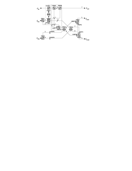
Fig. 3 shows a possible optical realization of this scheme. We utilize a heralded CNOT gate proposed in Pittman et al. (2001), with the success probability 1/4141/4. Another CNOT gate need not be heralded and a post-selected CNOT gate given in Ralph et al. (2002) can work with the success probability 1/9191/9. However, as in our scheme the target state of the second CNOT gate is known (|Vket𝑉|V\rangle or vacuum), it turns out that the gate can be optimized for maximum success probability 1/6161/6 Ralph (2004); Ralph et al. (2007) (see the gate in the dashed box). Therefore in the case of fivefold coincidence, i.e., detection of exact one photon in each of the output modes c𝑐c, t1subscript𝑡1t_{1} and t2subscript𝑡2t_{2} and successful detection at D1 and D2, the gate succeeds with a total probability of success 1/4×1/6×1/8=1/1925.2×10314161811925.2superscript1031/4\times 1/6\times 1/8=1/192\approx 5.2\times 10^{-3}. As an ancillary Bell state is needed, to implement this scheme requires at least a five-photon source, which is available at present Zhao et al. (2004); Zhang et al. (2006); Lu et al. (2007), and therefore our scheme is feasible with current technology. However, the low success probability of our scheme would make the experiment more difficult and longer time detection would be needed.

IV Post-selected Fredkin gate assisted by time entanglement

In this section we introduce another post-selected Fredkin gate assisted by time entanglement. Let us first remind the reader of the CNOT gate presented by Sanaka et al. Sanaka et al. (2002) (see Fig. 4).

Refer to caption
Figure 4: Schematic of the controlled-not (CNOT) gate demonstrated in Sanaka et al. (2002). Lowercase letters label the beams. Polarizing beam splitters (PBS) transmit horizontally polarized photons and reflect vertically polarized photons. The control (target) photon is input in mode cinsubscript𝑐inc_{\text{in}} (tinsubscript𝑡int_{\text{in}}) and output is in mode coutsubscript𝑐outc_{\text{out}} (toutsubscript𝑡outt_{\text{out}}). BS1 and BS2 are both balanced beam splitters. HWP is a half-wave plate set to 45superscript4545^{\circ}.

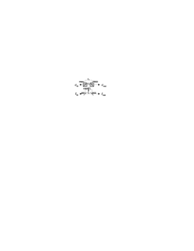
The control and target photons are a photon pair generated by spontaneous parametric down-conversion pumped by a Continuous Wave (CW) laser. Such a source is said to be time-energy entangled Franson (1989) as the photon pair is in a superposition of many possible emission times. The control photon is split along the short (cLsubscript𝑐𝐿c_{L}) or long (cSsubscript𝑐𝑆c_{S}) path at PBS1 and combined again in the same path at PBS2. The target photon is split along the short (tLsubscript𝑡𝐿t_{L}) or long (tSsubscript𝑡𝑆t_{S}) path at the first beam splitter BS1 and combined again in the same path at BS2. A HWP oriented at 45superscript4545^{\circ} rotates the polarization state of the photon taking the long path by 90superscript9090^{\circ}. The path-length difference ΔLΔ𝐿\Delta L of cLsubscript𝑐𝐿c_{L} and cSsubscript𝑐𝑆c_{S} is the same with that of tLsubscript𝑡𝐿t_{L} and tSsubscript𝑡𝑆t_{S} and satisfies the condition

lSPDCΔLlpump,subscript𝑙SPDCΔ𝐿subscript𝑙pumpl_{\text{SPDC}}\leqslant\Delta L\leqslant l_{\text{pump}}, (9)

where lSPDCsubscript𝑙SPDCl_{\text{SPDC}} is the coherence length of the down-converted photon and lpumpsubscript𝑙pumpl_{\text{pump}} is the spectral width of the pump laser. Conditioned on coincidence of detection with the time window of the coincidence counter satisfying ΔT<ΔL/cΔ𝑇Δ𝐿𝑐\Delta T<\Delta L/c, we can write the evolution of an arbitrary input state as

b1|Hcin|Htin+limit-fromsubscript𝑏1subscriptket𝐻subscript𝑐insubscriptket𝐻subscript𝑡in\displaystyle b_{1}\mbox{$|H\rangle$}_{c_{\text{in}}}\mbox{$|H\rangle$}_{t_{\text{in}}}+ b2|Hcin|Vtin+b3|Vcin|Htinsubscript𝑏2subscriptket𝐻subscript𝑐insubscriptket𝑉subscript𝑡insubscript𝑏3subscriptket𝑉subscript𝑐insubscriptket𝐻subscript𝑡in\displaystyle b_{2}\mbox{$|H\rangle$}_{c_{\text{in}}}\mbox{$|V\rangle$}_{t_{\text{in}}}+b_{3}\mbox{$|V\rangle$}_{c_{\text{in}}}\mbox{$|H\rangle$}_{t_{\text{in}}}
+b4|Vcin|Vtinsubscript𝑏4subscriptket𝑉subscript𝑐insubscriptket𝑉subscript𝑡in\displaystyle+b_{4}\mbox{$|V\rangle$}_{c_{\text{in}}}\mbox{$|V\rangle$}_{t_{\text{in}}} \displaystyle\longrightarrow
b1|HScoutsubscript𝑏1subscriptketsuperscript𝐻𝑆subscript𝑐out\displaystyle b_{1}\mbox{$|H^{S}\rangle$}_{c_{\text{out}}} |HStout+b2|HScout|VStoutsubscriptketsuperscript𝐻𝑆subscript𝑡outsubscript𝑏2subscriptketsuperscript𝐻𝑆subscript𝑐outsubscriptketsuperscript𝑉𝑆subscript𝑡out\displaystyle\mbox{$|H^{S}\rangle$}_{t_{\text{out}}}+b_{2}\mbox{$|H^{S}\rangle$}_{c_{\text{out}}}\mbox{$|V^{S}\rangle$}_{t_{\text{out}}}
+b3|VLcoutsubscript𝑏3subscriptketsuperscript𝑉𝐿subscript𝑐out\displaystyle+b_{3}\mbox{$|V^{L}\rangle$}_{c_{\text{out}}} |VLtout+b4|VLcout|HLtout,subscriptketsuperscript𝑉𝐿subscript𝑡outsubscript𝑏4subscriptketsuperscript𝑉𝐿subscript𝑐outsubscriptketsuperscript𝐻𝐿subscript𝑡out\displaystyle\mbox{$|V^{L}\rangle$}_{t_{\text{out}}}+b_{4}\mbox{$|V^{L}\rangle$}_{c_{\text{out}}}\mbox{$|H^{L}\rangle$}_{t_{\text{out}}}, (10)

where bi(i=1,2,3,4)subscript𝑏𝑖𝑖1234b_{i}(i=1,2,3,4) is an arbitrary complex number satisfying normalization condition, and the superscript S𝑆S (L𝐿L) denotes the photon passing the short (long) path. Here the coincidence counting has post-selected out unwanted state components in which the control and target photons followed paths of different lengths. Because of the time-energy entanglement, paths of the same length are indistinguishable and so add coherently. The success probability is 1/4141/4.

Fig. 5 shows an optical realization of a post-selected Fredkin gate by replacing the four CNOT gates in Fig. 1 with the CNOT gates we have just introduced. Based on the analysis above, in the case of the input state given by Eq. (II), the successful output state can be found to be

a1|HSc|HSt1|HSt2+a2|HSc|HSt1|VSt2subscript𝑎1subscriptketsuperscript𝐻𝑆𝑐subscriptketsuperscript𝐻𝑆subscript𝑡1subscriptketsuperscript𝐻𝑆subscript𝑡2subscript𝑎2subscriptketsuperscript𝐻𝑆𝑐subscriptketsuperscript𝐻𝑆subscript𝑡1subscriptketsuperscript𝑉𝑆subscript𝑡2\displaystyle a_{1}\mbox{$|H^{S}\rangle$}_{c}\mbox{$|H^{S}\rangle$}_{t_{1}}\mbox{$|H^{S}\rangle$}_{t_{2}}+a_{2}\mbox{$|H^{S}\rangle$}_{c}\mbox{$|H^{S}\rangle$}_{t_{1}}\mbox{$|V^{S}\rangle$}_{t_{2}}
+\displaystyle+ a3|HSc|VSt1|HSt2+a4|HSc|VSt1|VSt2subscript𝑎3subscriptketsuperscript𝐻𝑆𝑐subscriptketsuperscript𝑉𝑆subscript𝑡1subscriptketsuperscript𝐻𝑆subscript𝑡2subscript𝑎4subscriptketsuperscript𝐻𝑆𝑐subscriptketsuperscript𝑉𝑆subscript𝑡1subscriptketsuperscript𝑉𝑆subscript𝑡2\displaystyle a_{3}\mbox{$|H^{S}\rangle$}_{c}\mbox{$|V^{S}\rangle$}_{t_{1}}\mbox{$|H^{S}\rangle$}_{t_{2}}+a_{4}\mbox{$|H^{S}\rangle$}_{c}\mbox{$|V^{S}\rangle$}_{t_{1}}\mbox{$|V^{S}\rangle$}_{t_{2}}
+\displaystyle+ a5|VLc|HLt1|HLt2+a6|VLc|VLt1|HLt2subscript𝑎5subscriptketsuperscript𝑉𝐿𝑐subscriptketsuperscript𝐻𝐿subscript𝑡1subscriptketsuperscript𝐻𝐿subscript𝑡2subscript𝑎6subscriptketsuperscript𝑉𝐿𝑐subscriptketsuperscript𝑉𝐿subscript𝑡1subscriptketsuperscript𝐻𝐿subscript𝑡2\displaystyle a_{5}\mbox{$|V^{L}\rangle$}_{c}\mbox{$|H^{L}\rangle$}_{t_{1}}\mbox{$|H^{L}\rangle$}_{t_{2}}+a_{6}\mbox{$|V^{L}\rangle$}_{c}\mbox{$|V^{L}\rangle$}_{t_{1}}\mbox{$|H^{L}\rangle$}_{t_{2}}
+\displaystyle+ a7|VLc|HLt1|VLt2+a8|VLc|VLt1|VLt2.subscript𝑎7subscriptketsuperscript𝑉𝐿𝑐subscriptketsuperscript𝐻𝐿subscript𝑡1subscriptketsuperscript𝑉𝐿subscript𝑡2subscript𝑎8subscriptketsuperscript𝑉𝐿𝑐subscriptketsuperscript𝑉𝐿subscript𝑡1subscriptketsuperscript𝑉𝐿subscript𝑡2\displaystyle a_{7}\mbox{$|V^{L}\rangle$}_{c}\mbox{$|H^{L}\rangle$}_{t_{1}}\mbox{$|V^{L}\rangle$}_{t_{2}}+a_{8}\mbox{$|V^{L}\rangle$}_{c}\mbox{$|V^{L}\rangle$}_{t_{1}}\mbox{$|V^{L}\rangle$}_{t_{2}}. (11)
Refer to caption
Figure 5: Optical realization of a post-selected linear optical Fredkin gate assisted by time entanglement. Lowercase letters and numbers label the beams. Photons in beams cinsubscript𝑐inc_{\text{in}}, t1insubscript𝑡1int_{1\text{in}} and t2insubscript𝑡2int_{2\text{in}} are the control and two target qubits. Polarizing beam splitters (PBS) transmit horizontally polarized photons and reflect vertically polarized photons. BS is balanced beam splitter. Half-wave plates HWP1 and HWP3 are oriented at 67.5superscript67.567.5^{\circ}. HWP2 and HWP4 are set to 22.5superscript22.522.5^{\circ}. HWP5, HWP6, HWP7 and HWP8 are set to 45superscript4545^{\circ}. The gate succeeds in the case of threefold coincidence detection in the output modes c𝑐c, t1subscript𝑡1t_{1} and t2subscript𝑡2t_{2}.

From Eqs. (IV) and (IV), we can see that to make the output state entangled the three input photons need be time-entangled in the two time bins, “S𝑆S” and “L𝐿L”. This scheme needs no ancillary photons and the probability of success is 1/641641/64. Three qubit time entangled states of the type required, i.e. in which a triple coincidence is in a superposition of many times, have been described in Keller et al. (1998); Hnilo (2005); Dell Anno et al. (2006), however, an experimental demonstration of such states has not yet been made.

V Conclusions

We have discussed the implementation of Fredkin gate with linear optics and single photons. We have presented a heralded method using four heralded CNOT gates. Our method needs less ancillary photons than that in Smolin and DiVincenzo (1996), but is less efficient than Fiurášek’s scheme Fiurášek (2006). We have also simplified the heralded scheme to a post-selected one by replacing two CNOT gates with two HWPs. This scheme needs only two ancillary photons, and therefore is feasible with existing technology. However, the low success probability would make the experiment more difficult. The other post-selected Fredkin gate we have proposed is assisted by time entanglement. Although this scheme needs no ancillary photons, the three-photon time entangled source required is not available at present.

It should be noted that since the post-selected schemes work in the coincidence basis, such schemes could not be scalable unless photon-number Quantum nondemolition (QND) detectors were added to each output beam, nevertheless they open the door for the first time to experimental tests of an optical Fredkin gate and would make its application possible. We hope our proposals will stimulate such investigations of Fredkin gate.

Acknowledgements.
YXG thanks Yun-Feng Huang for useful discussions. YXG and GCG were funded by National Fundamental Research Program (Grant No. 2006CB921907), National Natural Science Foundation of China (Grant No. 60121503 and No. 60621064), Innovation Funds from Chinese Academy of Sciences, International Cooperate Program from CAS and Ministry of Science & Technology of China. TCR was supported by the DTO-funded U.S.Army Research Office Contract No. W911NF-05-0397 and the Australian Research Council.

References

  • Nielsen and Chuang (2000) M. A. Nielsen and I. L. Chuang, Quantum Computation and Quantum Information (Cambridge University, Cambridge, England, 2000).
  • Spiller et al. (2005) T. P. Spiller, W. J. Munro, S. D. Barrett, and P. Kok, Contemp. Phys. 46, 407 (2005).
  • Knill et al. (2001) E. Knill, R. Laflamme, and G. J. Milburn, Nature (London) 409, 46 (2001).
  • Kok et al. (2007) P. Kok, W. J. Munro, K. Nemoto, T. C. Ralph, J. P. Dowling, and G. J. Milburn, Rev. Mod. Phys. 79, 135 (2007).
  • Fredkin and Toffoli (1982) E. Fredkin and T. Toffoli, Int. J. Theor. Phys. 21, 219 (1982).
  • Smolin and DiVincenzo (1996) J. A. Smolin and D. P. DiVincenzo, Phys. Rev. A 53, 2855 (1996).
  • Pittman et al. (2001) T. B. Pittman, B. C. Jacobs, and J. D. Franson, Phys. Rev. A 64, 062311 (2001).
  • Fiurášek (2006) J. Fiurášek, Phys. Rev. A 73, 062313 (2006).
  • Milburn (1989) G. J. Milburn, Phys. Rev. Lett. 62, 2124 (1989).
  • Ralph et al. (2007) T. C. Ralph, K. J. Resch, and A. Gilchrist, Phys. Rev. A 75, 022313 (2007).
  • Ralph et al. (2002) T. C. Ralph, N. K. Langford, T. B. Bell, and A. G. White, Phys. Rev. A 65, 062324 (2002).
  • Ralph (2004) T. C. Ralph, Phys. Rev. A 70, 012312 (2004).
  • Zhao et al. (2004) Z. Zhao, Y.-A. Chen, A.-N. Zhang, T. Yang, H. J. Briegel, and J.-W. Pan, Nature (London) 430, 54 (2004).
  • Zhang et al. (2006) Q. Zhang, A. Goebel, C. Wagenknecht, Y. A. Chen, B. Zhao, T. Yang, A. Mair, J. Schmiedmayer, and J. W. Pan, Nat. Phys. 2, 678 (2006).
  • Lu et al. (2007) C. Y. Lu, X. Q. Zhou, O. Gu¨¨𝑢\ddot{u}hne, W. B. Gao, J. Zhang, Z. S. Yuan, A. Goebel, T. Yang, and J. W. Pan, Nat. Phys. 3, 91 (2007).
  • Sanaka et al. (2002) K. Sanaka, K. Kawahara, and T. Kuga, Phys. Rev. A 66, 040301 (2002).
  • Franson (1989) J. D. Franson, Phys. Rev. Lett. 62, 2205 (1989).
  • Keller et al. (1998) T. E. Keller, M. H. Rubin, Y. Shih, and L.-A. Wu, Phys. Rev. A 57, 2076 (1998).
  • Hnilo (2005) A. A. Hnilo, Phys. Rev. A 71, 033820 (2005).
  • Dell Anno et al. (2006) F. Dell Anno, S. D. Siena, and F. Illuminati, Phys. Rep. 428, 53 (2006).