Large MIMO Detection: A Low-Complexity Detector at High Spectral Efficiencies
Abstract
We consider large MIMO systems, where by ‘large’ we mean number of transmit and receive antennas of the order of tens to hundreds. Such large MIMO systems will be of immense interest because of the very high spectral efficiencies possible in such systems. We present a low-complexity detector which achieves uncoded near-exponential diversity performance for hundreds of antennas (i.e., achieves near SISO AWGN performance in a large MIMO fading environment) with an average per-bit complexity of just , where and denote the number of transmit and receive antennas, respectively. With an outer turbo code, the proposed detector achieves good coded bit error performance as well. For example, in a 600 transmit and 600 receive antennas V-BLAST system with a high spectral efficiency of 200 bps/Hz (using BPSK and rate-1/3 turbo code), our simulation results show that the proposed detector performs close to within about 4.6 dB from theoretical capacity. We also adopt the proposed detector for the low-complexity decoding of high-rate non-orthogonal space-time block codes (STBC) from division algebras (DA). For example, we have decoded the full-rate non-orthogonal STBC from DA using the proposed detector and show that it performs close to within about 5.5 dB of the capacity using 4-QAM and rate-3/4 turbo code at a spectral efficiency of 24 bps/Hz. The practical feasibility of the proposed high-performance low-complexity detector could potentially trigger wide interest in the implementation of large MIMO systems. We also illustrate the applicability of the proposed detector in the low-complexity detection of large multicarrier CDMA (MC-CDMA) systems. In large MC-CDMA systems with hundreds of users, the proposed detector is shown to achieve near single-user performance at an average per-bit complexity linear in number of users, which is quite appealing for its use in practical CDMA systems.
Index Terms:
Large MIMO systems, V-BLAST, non-orthogonal STBCs, low-complexity detection, high spectral efficiency, multicarrier CDMA.I Introduction
Multiple-input multiple-output (MIMO) techniques offer transmit diversity and high data rates through the use of multiple antennas at both transmitter and receiver sides [1]-[6]. A key component of a MIMO system is the MIMO detector at the receiver, which, in practice, is often the bottleneck for the overall performance and complexity. MIMO detectors including sphere decoder and several of its variants [7]-[15] achieve near maximum likelihood (ML) performance at the cost of high complexity. Other well known detectors including ZF (zero forcing), MMSE (minimum mean square error), and ZF-SIC (ZF with successive interference cancellation) detectors [3],[16] are attractive from a complexity view point, but achieve relatively poor performance. For example, the ZF-SIC detector (i.e., the well known V-BLAST detector with ordering [17],[18]) does not achieve the full diversity in the system. The MMSE-SIC detector has been shown to achieve optimal performance [3]. However, these detectors are prohibitively complex for large number of antennas of the order of tens to hundreds. With small number of antennas, the high capacity potential of MIMO is not fully exploited. A key issue with using large number of antennas, however, is the high detection complexities involved.
In this paper, we focus on large MIMO systems, where by ‘large’ we mean number of transmit and receive antennas of the order of tens to hundreds. Such large MIMO systems will be of immense interest because of the very high spectral efficiencies possible in such systems. For example, in a V-BLAST system, increased number of transmit antennas means increased data rate without bandwidth increase. However, major bottlenecks in realizing such large MIMO systems include physical placement of large number of antennas in communication terminals111We, however, point out that there can be several large MIMO applications where antenna placement need not be a major issue. An example of such a scenario is to provide high-speed back-haul connectivity between base stations using large MIMO links, where large number of antennas can be placed at the base stations. Also, tens of antennas can be placed in moderately sized terminals (e.g., laptops, set top boxes) that can enable interesting spectrally efficient, high data rate applications like wireless IPTV., lack of practical low-complexity detectors for such large systems, and channel estimation issues. In this paper, we address the second problem in the above (i.e., low-complexity large MIMO detection). Specifically, we present a low-complexity detector for large MIMO systems, including V-BLAST as well as high-rate non-orthogonal space-time block codes (STBC) [29].
The proposed low-complexity detector has its roots in past work on Hopfield neural network (HNN) based algorithms for image restoration [19],[20], which are meant to handle large digital images. HNN based image restoration algorithms in [20] are applied to multiuser detection (MUD) in CDMA systems on AWGN channels in [21]. This detector, referred to as the likelihood ascent search (LAS) detector, essentially searches out a sequence of bit vectors with monotonic likelihood ascent and converges to a fixed point in finite number of steps [21]. The power of the LAS detector for CDMA lies in its linear average per-bit complexity in number of users, and its ability to perform very close to ML detector for large number of users. Taking the cue from LAS detector’s complexity and performance superiority in large systems, we, in this paper, successfully adopt the LAS detector for large MIMO systems and report interesting results.
We refer to the proposed detector as MF/ZF/MMSE-LAS222Throughout the paper, whenever we write MF/ZF/MMSE-LAS, we mean MF-LAS, ZF-LAS, and MMSE-LAS. detector depending on the initial vector used in the algorithm; MF-LAS detector uses the matched filter output as the initial vector, and ZF-LAS and MMSE-LAS detectors employ ZF and MMSE outputs, respectively, as the initial vector. Our major findings in this paper are summarized as follows:
Detection in Large V-BLAST Systems:
-
•
In an uncoded V-BLAST system with BPSK, the proposed detector achieves near-exponential diversity for hundreds of antennas (i.e., achieves near SISO AWGN performance). For example, the proposed detector nearly renders a MIMO fading channel into 200 parallel, non-interfering SISO AWGN channels. The detector achieves this excellent performance with an average per-bit complexity of just , where and denote the number of transmit and receive antennas, respectively.
-
•
With an outer turbo code, the proposed detector achieves good coded bit error performance as well. For example, in a 600 transmit and 600 receive antennas V-BLAST system with a high spectral efficiency of 200 bps/Hz (using BPSK and rate-1/3 turbo code), our simulation results show that the proposed detector performs close to within about 4.6 dB from the theoretical capacity. We note that performance with such closeness to capacity has not been reported in the literature so far for such large number of antennas using a practical complexity detector.
Detection of Large Full-Rate Non-Orthogonal STBCs:
-
•
We have adopted the proposed detector for the low-complexity decoding of large full-rate non-orthogonal STBCs from division algebras (DA) in [29]. We decode the full-rate non-orthogonal STBC from DA (which has 256 data symbols in one STBC matrix) using the proposed detector and show that it performs close to within about 5.5 dB from capacity using 4-QAM and rate-3/4 turbo code at a spectral efficiency of 24 bps/Hz.
-
•
We point out that because of the high complexities involved in the decoding of large non-orthogonal STBCs using other known detectors, the BER performance of such high-rate large non-orthogonal STBCs have not been reported in the literature so far. The very fact that we could show the simulated BER performance plots (both uncoded as well as turbo coded) for a full-rate non-orthogonal STBC with 256 complex symbols in one STBC matrix in itself is a clear indication of the superior low-complexity attribute of the proposed detector. To our knowledge, this is the first time that simulated BER plots and nearness to capacity results for a full-rate STBC from DA are reported in the literature; this became feasible due to the low-complexity attribute of the proposed detector.
Detection in Large Multicarrier CDMA Systems:
-
•
We also illustrate the applicability of the proposed detector in the low-complexity detection of large multicarrier CDMA (MC-CDMA) systems. In large MC-CDMA systems with hundreds of users, the proposed detector is shown to achieve near single-user performance, at an average per-bit complexity linear in number of users, which is quite appealing for its use in practical CDMA systems.
The rest of the paper is organized as follows. In section II, we present the proposed LAS detector for V-BLAST systems and its complexity. The simulated uncoded and coded BER performance of the proposed detector for V-BLAST is presented in section III. Decoding of non-orthogonal STBCs and BER performance results are presented in section IV. The LAS detector for MC-CDMA and the corresponding BER performance results are presented in section V. Conclusions are presented in section VI.
II Proposed LAS Detector for Large MIMO
In this section, we present the proposed LAS detector for V-BLAST and its complexity. Consider a V-BLAST system with transmit antennas and receive antennas, , where symbols are transmitted from transmit antennas simultaneously. Let be the symbol333Although we present the detector for BPSK here, we have adopted it for -QAM/-PAM as well. transmitted by the th transmit antenna. Each transmitted symbol goes through the wireless channel to arrive at each of receive antennas. Denote the path gain from transmit antenna to receive antenna by . Considering a flat-fading MIMO channel with rich scattering, the signal received at antenna , denoted by , is given by
| (1) |
The , , , are assumed to be i.i.d. complex Gaussian r.v’s (i.e., fade amplitudes are Rayleigh distributed) with zero mean and , where and are the real and imaginary parts of . The noise sample at the th receive antenna, , is assumed to be complex Gaussian with zero mean, and , , are assumed to be independent with , where is the average energy of the transmitted symbols, and is the average received SNR per receive antenna [2]. Collecting the received signals from all receive antennas, we write444We adopt the following notation: Vectors are denoted by boldface lowercase letters, and matrices are denoted by boldface uppercase letters. , , and denote transpose, conjugate, and conjugate transpose operations, respectively. and denote the real and imaginary parts of the complex argument.
| (2) |
where is the -length received signal vector, is the -length transmitted bit vector, H denotes the channel matrix with channel coefficients , and is the -length noise vector. H is assumed to be known perfectly at the receiver but not at the transmitter.
II-A Proposed LAS Algorithm
The proposed LAS algorithm essentially searches out a sequence of bit vectors until a fixed point is reached; this sequence is decided based on an update rule. In the V-BLAST system considered, for ML detection [16], the most likely is taken as that which maximizes
| (3) |
The likelihood function in (3) can be written as
| (4) |
where
| (5) | |||||
| (6) |
Update Criterion in the Search Procedure: Let denote the bit vector tested by the LAS algorithm in the search step . The starting vector can be the output vector from any known detector. When the output vector of the MF detector is taken as the , we call the resulting LAS detector as the MF-LAS detector. We define ZF-LAS and MMSE-LAS detectors likewise. Given , the algorithm obtains through an update rule until a fixed point is reached. The update is made in such a way that the change in likelihood from step to , denoted by , is positive, i.e.,
| (7) |
An expression for the above change in likelihood can be obtained in terms of the gradient of the likelihood function as follows. Let denote the gradient of the likelihood function evaluated at , i.e.,
| (8) |
where
| (9) |
Using (4) in (7), we can write
| (10) | |||||
Now, defining
| (11) |
and observing that , adding & subtracting the term to the RHS of (10), and further observing that , we can simplify (10) as
| (12) | |||||
where
| (13) |
Now, given , , and , the objective is to obtain from such that in (12) is positive. Potentially any one or several bits in can be flipped (i.e., changed from +1 to -1 or vice versa) to get . We refer to the set of bits to be checked for possible flip in a step as a check candidate set. Let denote the check candidate set at step . With the above definitions, it can be seen that the likelihood change at step , given by (12), can be written as
| (14) |
where , , and are the th elements of the vectors , , and , respectively. As shown in [21] for synchronous CDMA on AWGN, the following update rule can be easily shown to achieve monotonic likelihood ascent (i.e., if there is at least one bit flip) in the V-BLAST system as well.
LAS Update Algorithm: Given and an initial bit vector , bits in are updated as per the following update rule:
| (15) |
where is a threshold for the th bit in the th step is taken to be
| (16) |
where is the element in the th row and th column of the matrix .
It is noted that different choices can be made to specify the sequence of . One of the simplest sequences correspond to checking one bit in each step for a possible flip, which is termed as a sequential LAS (SLAS) algorithm with constant threshold, The sequence of in SLAS can be such that the indices of bits checked in successive steps are chosen circularly or randomly. Checking of multiple bits for possible flip is also possible. Let denote the set of indices of the bits flipped according to the update rule in (15) at step . Then the updated bit vector can be written as
| (17) |
where is the th coordinate vector. Using (17) in (8), the gradient vector for the next step can be obtained as
| (18) | |||||
where denotes the th column of the matrix . The LAS algorithm keeps updating the bits in each step based on the update rule given in (15) until for some , in which case is a fixed point, and it is taken as the detected bit vector and the algorithm terminates.
II-B Complexity of the Proposed Detector for V-BLAST
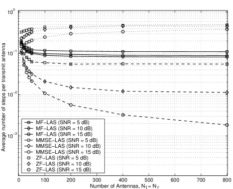
In terms of complexity, given an initial vector, the the LAS operation part alone has an average per-bit complexity of . This can be explained as follows. The complexity involved in the LAS operation is due to three components: initial computation of in (8), update of in each step as per (18), and the average number of steps required to reach a fixed point. Computation of requires the computation of for each MIMO fading channel realization see Eqns. (8), (9), and (6), which requires a per-bit complexity of order . Update of in the th step as per (18) using sequential LAS requires a complexity of , and hence a constant per-bit complexity. Regarding the complexity component , we obtained the average number of steps required to reach a fixed point for sequential LAS through simulations. We observed that the average number of steps required is linear in , i.e., constant per-bit complexity where the constant depends on SNR, , , and the initial vector (see Fig. 5). Putting the complexities of , , and in the above together, we see that the average per-bit complexity of LAS operation alone is . In addition to the above, the initial vector generation also contributes to the overall complexity. The average per-bit complexity of generating initial vectors using MF, ZF, and MMSE are , , and , respectively. The higher complexity of ZF and MMSE compared to MF is because of the need to perform matrix inversion operation in ZF/MMSE. Again, putting the complexities of the LAS part and the initial vector generation part together, we see that the overall average per-bit complexity of the proposed MF/ZF/MMSE-LAS detector is . This complexity is an order superior compared to the well known ZF-SIC detector with ordering555Henceforth, we use the term ‘ZF-SIC’ to always refer ‘ZF-SIC with ordering’., whose per-bit complexity is .
III LAS Detector Performance in V-BLAST
In this section, we present the uncoded/coded BER performance of the proposed LAS detector in V-BLAST obtained through simulations, and compare with those of other detectors. The LAS algorithm used is the sequential LAS with circular checking of bits starting from the first antenna bit. We also quantify how far is the proposed detector’s turbo coded BER performance away from the theoretical capacity. The SNRs in all the BER performance figures are the average received SNR per received antenna, , defined in Sec. II [2].
III-A Uncoded BER Performance
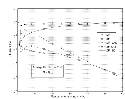
MF/ZF-LAS performs increasingly better than ZF-SIC for increasing : In Fig. 1, we plot the uncoded BER performance of the MF-LAS, ZF-LAS and ZF-SIC detectors for V-BLAST as a function of at an average received SNR of 20 dB with BPSK. The performance of the MF and ZF detectors are also plotted for comparison. From Fig. 1, we observe the following:
-
•
The BER at is nothing but the SISO flat Rayleigh fading BER for BPSK, given by which is equal to for dB [22]. While the performance of MF and ZF degrade as is increased, the performance of ZF-SIC improves for antennas up to , beyond which a flooring effect occurs. This improvement is likely due to the potential diversity in the ordering (selection) in ZF-SIC, whereas the flooring for is likely due to interference being large beyond the cancellation ability of the ZF-SIC.
-
•
The behavior of MF-LAS and ZF-LAS for increasing are interesting. Starting with the MF output as the initial vector, the MF-LAS always achieves better performance than MF. More interestingly, this improved performance of MF-LAS compared to that of MF increases remarkably as increases. For example, for , the performance improves by an order in BER (i.e., BER for MF versus BER for MF-LAS), whereas for the performance improves by four-orders in BER (i.e., BER for MF versus BER for MF-LAS). This is due to the large system effect in the LAS algorithm which is able to successfully pick up much of the diversity possible in the system. This large system performance superiority of the LAS is in line with the observations/results reported in [21] for a large CDMA system large number of antennas in our case, whereas it was large number of users in [21].
-
•
While the ZF-LAS performs slightly better than ZF-SIC for antennas less than 4, ZF-SIC performs better than ZF-LAS for antennas in the range 4 to 24. This is likely because, for antennas less than 4, the BER of ZF is small enough for the LAS to clean up the ZF initial vector into an output vector better than the ZF-SIC output vector. However, for antennas in the range of 4 to 24, the BER of ZF gets high to an extent that the ZF-LAS is less effective in cleaning the initial vector beyond the diversity performance achieved by the ZF-SIC. A more interesting observation, however, is that for antennas greater than 25, the large system effect of ZF-LAS starts showing up. So, in the large system setting (e.g., antennas more than 25 in Fig. 1), the ZF-LAS performs increasingly better than ZF-SIC for increasing . We found the number of antennas at which the cross-over between ZF-SIC and ZF-LAS occurs to be different for different SNRs.
-
•
Another observation in Fig. 1 is that for antennas greater than 50, MF-LAS performs better than ZF-LAS. This behavior can be explained by observing the performance comparison between MF and ZF detectors given in the same figure. For more than 50 antennas, MF performs slightly better than ZF. It is known that ZF detector can perform worse than MF detector under high noise/interference conditions [16] (here high interference due to large ). Hence, starting with a better initial vector, MF-LAS performs better than ZF-LAS.
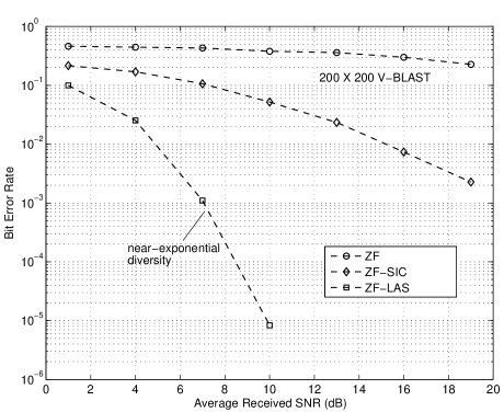
ZF-LAS outperforms ZF-SIC in large V-BLAST systems both in complexity & diversity: In Fig. 2, we present an interesting comparison of the uncoded BER performance between ZF, ZF-LAS and ZF-SIC, as a function of average SNR for a V-BLAST system. This system being a large system, the ZF-LAS has a huge complexity advantage over ZF-SIC as pointed out before in Sec. II-B. In fact, although we have taken the effort to show the performance of ZF-SIC at such a large number of antennas like 200, we had to obtain these simulation points for ZF-SIC over days of simulation time, whereas the same simulation points for ZF-LAS were obtained in just few hours. This is due to the complexity of ZF-SIC versus complexity of ZF-LAS, as pointed out in Sec. II-B. More interestingly, in addition to this significant complexity advantage, ZF-LAS is able to achieve a much higher order of diversity (in fact, near-exponential diversity) in BER performance compared to ZF-SIC (which achieves only a little better than first order diversity). This is clearly evident from the slopes of the BER curves of ZF-LAS and ZF-SIC. Note that the BER curve for ZF-LAS is almost the same as the uncoded BER curve for BPSK on a SISO AWGN channel, given by [22]. This means that the proposed detector nearly renders a MIMO fading channel into 200 parallel, non-interfering SISO AWGN channels.
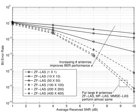
LAS Detector’s performance with hundreds of antennas: As pointed earlier, obtaining ZF-SIC results for more than even 50 antennas requires very long simulation run times, which is not the case with ZF-LAS. In fact, we could easily generate BER results for up to 400 antennas for ZF-LAS, which are plotted in Fig. 3. The key observations in Fig. 3 are that the average SNR required to achieve a certain BER performance keeps reducing for increasing number of antennas for ZF-LAS, and increasing the number of antennas results in increased orders of diversity achieved (close to SISO AWGN performance for 200 and 400 antennas). We have also observed from our simulations that for large number of antennas, the LAS algorithm converges to almost the same near-ML performance regardless of the initial vector chosen. For example, for the case of 200 and 400 antennas in Fig. 3, the BER performance achieved by ZF-LAS, MF-LAS, and MMSE-LAS are almost the same (although we have not explicitly plotted the BER curves for MF-LAS and MMSE-LAS in Fig. 3). So, in such large MIMO systems setting, MF-LAS may be preferred over ZF/MMSE-LAS since ZF/MMSE-LAS require matrix inverse operation whereas MF-LAS does not.
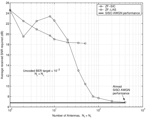
Observation in the above paragraph is explicitly brought out in Fig. 4, where we have plotted the average received SNR required to achieve a target uncoded BER of as a function of for ZF-LAS and ZF-SIC. It can be seen that the SNR required to achieve with ZF-LAS significantly reduces for increasingly large . For example, the required SNR reduces from about 25 dB for a SISO Rayleigh fading channel to about 7 dB for a V-BLAST system using ZF-LAS. As we pointed out in Fig. 3, this system performance is almost the same as that of a SISO AWGN channel where the SNR required to achieve BER is also close to 7 dB [22], i.e., dB.
III-B Turbo Coded BER Performance
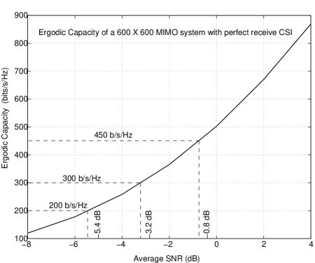
In this subsection, we present the turbo coded BER performance of the proposed LAS detector. We also quantify how far is the proposed detector’s performance away from the theoretical capacity. For a MIMO system model in Sec. II with perfect channel state information (CSI) at the receiver, the ergodic capacity is given by [5]
| (19) |
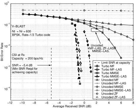
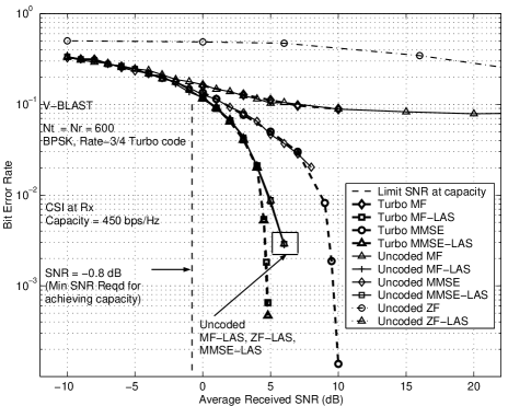
where is the identity matrix and is the average SNR per receive antenna. We have evaluated the capacity in (19) for a MIMO system through Monte-Carlo simulations and plotted it as a function of average SNR in Fig. 6. Figure 7 shows the simulated BER performance of the proposed LAS detector for a MIMO system with BPSK and rate-1/3 turbo code (i.e., spectral efficiency = 200 bps/Hz). Figure 8 shows similar performance plots for rate-3/4 turbo code at a spectral efficiency of 450 bps/Hz. From the capacity curve in Fig. 6, the minimum SNRs required at 200 bps/Hz and 450 bps/Hz spectral efficiencies are -5.4 dB and -0.8 dB, respectively. The following interesting observations can be made from Figs. 7 and 8:
-
•
In terms of uncoded BER, the performance of MF, ZF, and MMSE are different, with ZF and MMSE performing the worst and best, respectively. But the performance of MF-LAS, ZF-LAS, and MMSE-LAS are almost the same (near-exponential diversity performance) with the number of antennas being large ().
-
•
With a rate-1/3 turbo code (Fig. 7), all the LAS detectors considered (i.e., MF-LAS, ZF-LAS, MMSE-LAS) achieve almost the same performance, which is about 4.6 dB away from capacity666We point out that the turbo coded BER curves shown in Figs. 7 to 11 in [23] have been plotted erroneously with an SNR shift of dB, where is the turbo code rate, which amounted to a pessimistic prediction of nearness to capacity. Here, we have corrected those plotting errors. Figures 7, 8, 9 and the nearness to capacity results given in Table-I in this paper are the corrected ones. (i.e., near-vertical fall of coded BER occurs at about -0.8 dB). Turbo coded MF/MMSE without LAS also achieve good performance in this case (i.e., less than only 2 dB away from turbo coded MF/ZF/MMSE-LAS performance). This is because the uncoded BER of MF and MMSE at around 0 to 2 dB SNR are small enough for the turbo code to be effective. However, this is not the case with turbo coded ZF without LAS. As can be seen, in the range of SNRs shown, the uncoded BER of ZF without LAS is so high (close to 0.5) that the vertical fall of coded BER can happen only at very high SNRs, because of which we have not shown the performance of turbo coded ZF without LAS.
| Code Rate, | Min. SNR | Vertical fall of coded BER occurs at | |||
|---|---|---|---|---|---|
| Spect. Eff. | at capacity | Proposed LAS | ZF | MF | MMSE |
| Rate-1/3, | -5.4 dB | -0.8 dB | high | 1.2 dB | -0.3 dB |
| 200 bps/Hz | |||||
| Rate-1/2 | -3.2 dB | 1.5 dB | high | high | 3 dB |
| 300 bps/Hz | |||||
| Rate-3/4 | -0.8 dB | 4.8 dB | high | high | high |
| 450 bps/Hz | |||||
In Table I, we summarize the performance of various detectors in terms of their nearness to capacity in a V-BLAST system using BPSK, and rate-1/3, rate-1/2 and rate-3/4 turbo codes. From Table-I, it can be seen that there is a clear superiority of the proposed MF/ZF/MMSE-LAS over MF/MMSE without LAS in terms of coded BER (nearness to capacity) when high-rate turbo codes are used. For example, when a rate-3/4 turbo code is used the MF/ZF/MMSE-LAS performs to within about 5.6 dB from capacity, whereas the performance of rate-3/4 turbo coded MF/MMSE without LAS are much farther away from capacity.
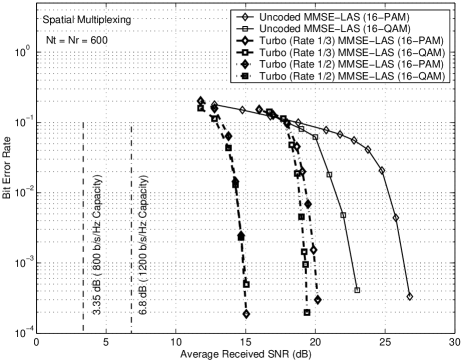
Performance of -PAM/-QAM: Although the LAS algorithm in Sec. II is presented assuming BPSK, it can be adopted for -ary modulation including -PAM and -QAM. In the case of BPSK, the elements of the data vector take values from . -PAM symbols take discrete values from where , , and -QAM is nothing but quadrature PAM. We have adopted the LAS algorithm for -PAM/-QAM and evaluated the performance of the LAS detector for 4-PAM/4-QAM and 16-PAM/16-QAM without and with coding. In -PAM/-QAM also, we have observed large system behavior of the proposed detector similar to those presented for BPSK. As an example, in Fig. 9, we present the uncoded and coded performance of the MMSE-LAS detector in a V-BLAST system for 16-PAM/16-QAM with rate-1/2 and rate-1/3 turbo codes at spectral efficiencies of 1200 bps/Hz and 800 bps/Hz, respectively. It can be observed that the LAS detector achieves performance close to within about 13 dB from the theoretical capacity.
Effect of Channel Estimation Errors: As we pointed out earlier, another key issue in large MIMO systems is channel estimation [31],[32]. We have evaluated the effect of channel estimation errors on the performance of the proposed detector in V-BLAST by considering an estimation error model, where the estimated channel matrix, , is taken to be where is the estimation error matrix, the entries of which are assumed to be i.i.d. complex Gaussian with zero mean and variance . Our simulation results showed that in a V-BLAST system with BPSK, rate-1/2 turbo code and LAS detection, the coded BER degradation compared to perfect channel estimation is only 0.2 dB and 0.6 dB for channel estimation error variances of and , respectively. The investigation of estimation algorithms and efficient pilot schemes for accurate channel estimation in large MIMO systems as such are important topics for further research.
IV Detection of Full-Rate Non-orthogonal STBCs
V-BLAST with large number of antennas can offer high spectral efficiencies, but it does not provide transmit diversity. On the other hand, well known orthogonal STBCs have the advantages of full transmit diversity and low decoding complexity, but suffer from rate loss for increased number of transmit antennas [2],[26]-[28]. Full-rate non-orthogonal STBCs from division algebras (DA) [29], on the other hand, are attractive for achieving high spectral efficiencies in addition to achieving full transmit diversity, using large number of transmit antennas.
Construction of full-rate non-orthogonal STBCs from DA for arbitrary number of transmit antennas is given by the matrix in (20.a) at the bottom of this page [29]. In (20.a), , , and , are the data symbols from a QAM alphabet. Note that there are data symbols in one STBC matrix. When and , the STBC in (20.a) achieves full transmit diversity (under ML decoding) as well as information-losslessness [29]. When , the code ceases to be of full-diversity (FD), but continues to be information-lossless (ILL) [30].
High spectral efficiencies with large can be achieved using this code construction. For example, with transmit antennas, the STBC from (20.a) with 16-QAM and rate-3/4 turbo code achieves a spectral efficiency of 48 bps/Hz. This high spectral efficiency is achieved along with the full-diversity of order .
However, since these STBCs are non-orthogonal, ML detection gets increasingly impractical for large number of transmit antennas, . Consequently, a key challenge in realizing the benefits of these full-rate non-orthogonal STBCs in practice is that of achieving near-ML performance for large number of transmit antennas at low detection complexities. Here, we show that near-ML detection of large MIMO signals originating from several tens of antennas using full-rate non-orthogonal STBCs is possible at practically affordable low complexities (using the proposed LAS detector), which is a significant new advancement that has not been reported in the MIMO detection literature so far.
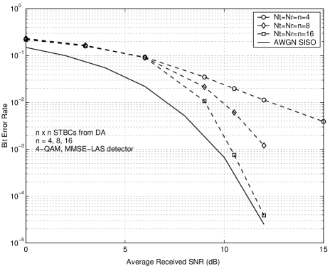
IV-A Uncoded BER Results for Large STBCs from DA
We have adopted the proposed LAS detector for the decoding of full-rate non-orthogonal STBCs. In Fig. 10, we present the uncoded BER of the LAS detector in decoding full-rate non-orthogonal STBCs from DA in (20.a) for , , and 4-QAM. It can be observed that as the STBC code size increases, the LAS performs increasingly better such that it achieves close to SISO AWGN performance (within 0.5 dB at BER and less) with the STBC. We point out that due to the high complexities involved in decoding large size STBCs using other known detectors, the BER performance of STBCs with large has not been reported in the literature so far. The very fact that we could show the simulated BER plots (both uncoded as well as turbo coded) for a STBC with 256 complex symbols in one STBC matrix in itself is a clear indication of the superior low-complexity attribute of the proposed LAS detector. To our knowledge, we are the first to report the simulated BER performance of a STBC from DA; this became feasible because of the low-complexity feature of the proposed detector. In addition, the achievement of near SISO AWGN performance with STBC is a significant result from an implementation view point as well, since 16 antennas can be easily placed in communication terminals of moderate size, which can make large MIMO systems practical.
IV-B Turbo Coded BER Results for Large STBCs from DA
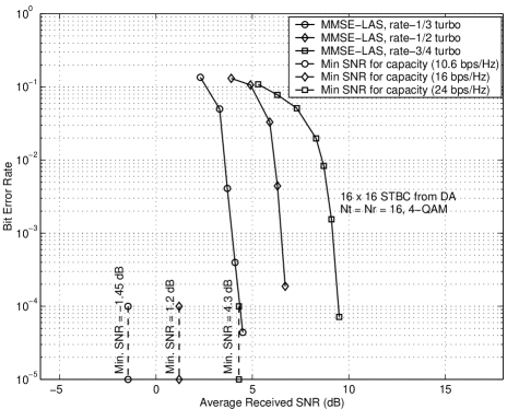
In Fig. 11, we show the coded BER performance of the STBC using different turbo code rates of 1/3, 1/2,
and 3/4. With 4-QAM, these turbo code rates along with the STBC from DA correspond to spectral efficiencies of 10.6 bps/Hz, 16 bps/Hz and 24 bps/Hz, respectively. The minimum SNRs required to achieve these capacities are also shown in Fig. 11. It can be observed that the proposed detector performs to within about 5.5 dB of the capacity, which is an impressive result. In all the turbo coded BER plots in this paper, we have used hard decision outputs from the LAS algorithm. In [25], we have proposed a method to generate soft decision outputs from the LAS algorithm for the individual bits that form the QAM/PAM symbols. With the proposed soft decision LAS outputs in [25], the coded performance is found to move closer to capacity by an additional 1 to 1.5 dB compared to that achieved using hard decision LAS outputs reported in this paper.
V LAS Detector for Multicarrier CDMA
In this section, we present the proposed LAS detector for multicarrier CDMA, its performance and complexity. Consider a -user synchronous multicarrier DS-CDMA system with subcarriers. Let denote the binary data symbol of the th user, which is sent in parallel on subcarriers [33],[34]. Let denote the number of chips-per-bit in the signature waveforms. It is assumed that the channel is frequency non-selective on each subcarrier and the fading is slow (assumed constant over one bit interval) and independent from one subcarrier to the other.
Let denote the -length received signal vector on the th subcarrier; i.e., is the output of the th user’s matched filter on the th subcarrier. Assuming that the inter-carrier interference is negligible, the -length received signal vector on the th subcarrier can be written in the form
| (20) |
where is the cross-correlation matrix on the th subcarrier, with its entries ’s denoting the normalized cross correlation coefficient between the signature waveforms of the th and th users on the th subcarrier. represents the channel matrix, given by
| (21) |
where the channel coefficients , , are assumed to be i.i.d. complex Gaussian r.v’s (i.e., fade amplitudes are Rayleigh distributed) with zero mean and , where and are the real and imaginary parts of . The -length data vector is given by
| (22) |
and the diagonal amplitude matrix is given by
| (23) |
where denotes the transmit amplitude of the th user. The -length noise vector is given by
| (24) |
where denotes the additive noise component of the th user on the th subcarrier, which is assumed to be complex Gaussian with zero mean with when and when . We assume that all the channel coefficients are perfectly known at the receiver.
V-A LAS Algorithm for MC-CDMA
We note that once the likelihood function for the MC-CDMA system in the above is obtained, it is straightforward to adopt the LAS algorithm for MC-CDMA. Accordingly, in the multicarrier system considered, the most likely is taken as that which maximizes
| (25) | |||||
The likelihood function in (25) can be written in a form similar to Eqn. (4.11) in [16] as
| (26) |
where
| (27) | |||||
| (28) |
Now observing the similarity between (26) and (4) in Sec. II-A, the LAS algorithm for MC-CDMA can be arrived at, along the same lines as that of V-BLAST in the previous section, with , and replaced by , , and , respectively, with all other notations, definitions, and procedures in the algorithm remaining the same.
V-B Complexity of the Proposed Detector for MC-CDMA
The complexity of the proposed detector for MC-CDMA can be analyzed in a similar manner as done for V-BLAST in Sec. II. First, given an initial vector, the LAS operation part alone in MC-CDMA has an average per-bit complexity of , which is due to initial computation of in (8), which requires complexity per bit, update of in each step as per (18), which requires complexity for sequential LAS, and hence constant per-bit complexity, and the average number of steps required to reach a fixed point, which, through simulations, is found to have a constant per-bit complexity. Next, the initial vector generation using MMSE or ZF has a per-bit complexity of for . Finally, combining the above complexities involved in the LAS part and the initial vector generation part, the overall average per-bit complexity of the MMSE/ZF-LAS detector for MC-CDMA is . The initial vector generation using MF has a per-bit complexity of only . Hence, if the MF output is used as the initial vector, then the overall average per-bit complexity of the MF-LAS is the same as that of the LAS alone, which is . For large , the performance of MF-LAS, ZF-LAS, and MMSE-LAS are almost the same (see Fig. 13), and hence MF-LAS is preferred because of its linear complexity in number of users, , for a given .
V-C Results and Discussions for MC-CDMA
We evaluated the BER performance of the proposed LAS detector for MC-CDMA through simulations. We evaluate the uncoded BER performance of the proposed LAS detector as a function of average SNR, number of users (), number of subcarriers (), and number of chips per bit (). We also evaluate the BER performance as a function of loading factor, , where, as done in the CDMA literature [16], we define . We call the system as underloaded when , fully loaded when , and overloaded when . Random binary sequences of length are used as the spreading sequences on each subcarrier. In order to make a fair comparison between the performance of MC-CDMA systems with different number of subcarriers, we keep the system bandwidth the same by keeping constant. Also, in that case we keep the total transmit power to be the same irrespective of the number of subcarriers used. In the simulation plots we show in this section, we have assumed that all users transmit with equal amplitude777We note that we have simulated the MF/ZF-LAS performance in near-far conditions as well. Even with near-far effect, the MF/ZF-LAS detectors have been observed to achieve near single-user performance.. The LAS algorithm used is the SLAS with circular checking of bits starting from the first user’s bit.
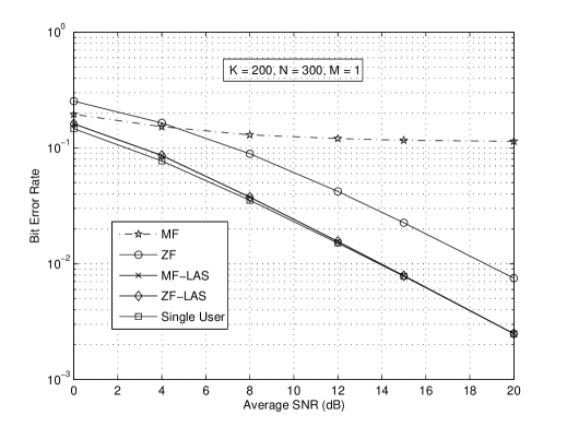
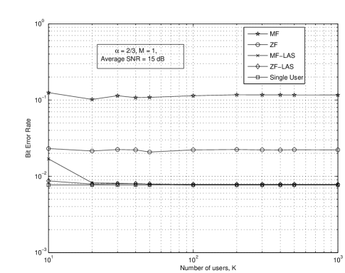
First, in Fig. 12, we present the BER performance of MF/ZF-LAS detectors as a function of average SNR in a single carrier (i.e., ) underloaded system, where we consider by taking users and chips per bit. For comparison purposes, we also plot the performance of MF and ZF without LAS. Single user (SU) performance, which corresponds to the case of no multiuser interference (i.e., ), is also shown as a lower bound on the achievable multiuser performance. From Fig. 12, we can observe that the performance of MF and ZF detectors are far away from the SU performance. Whereas, the ZF-LAS as well as MF-LAS detectors almost achieve the SU performance. We point out that, like ZF detector, other suboptimum detectors including MMSE, SIC, and PIC detectors [16] also do not achieve near SU performance for the considered loading factor of 2/3, whereas the MF-LAS detector achieves near SU performance, that too at a lesser complexity than these other suboptimum detectors.
Next, in Fig. 13, we show the BER performance of the MF/ZF-LAS detectors for as a function of number of users, , for a fixed value of at an average SNR of 15 dB. We varied from 10 to 1000 users. SU performance is also shown (as the bottom most horizontal line) for comparison. It can be seen that, for the fixed value of , both the MF-LAS as well as the ZF-LAS achieve near SU performance (even in the presence of 1000 users), whereas the ZF and MF detectors do not achieve the SU performance.
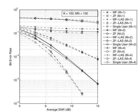
In Fig. 14, we show the BER performance of the MF/ZF-LAS detectors as a function of average SNR for different number of subcarriers, namely, , keeping a constant , for a fully loaded system (i.e., ) with . Keeping and for all cases means that for , for , and for . The SU performance for (1st order diversity), (2nd order diversity), and (4th order diversity) are also plotted for comparison. These diversities are essentially due to the frequency diversity effect resulting from multicarrier combining of signals from subcarriers. It is interesting to see that even in a fully loaded system, the MF/ZF-LAS detectors achieve all the frequency diversity possible in the system (i.e., MF/ZF-LAS detectors achieve SU performance with 1st, 2nd and 4th order diversities for and 4, respectively). On the other hand, ZF detector is unable to achieve the frequency diversity in the fully loaded system, and its performance is very poor compared to MF/ZF-LAS detectors.
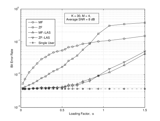
Next, in Fig. 15, we present the BER performance of ZF/MF-LAS detectors in a MC-CDMA system with as a function of loading factor, , where we vary from to 1.5. We realize this variation in by fixing , , and varying from 300 to 5. The average SNR considered is 8 dB. From Fig. 15, it can be observed that as increases all detectors loose performance, but the MF/ZF-LAS detectors can offer relatively good performance even at overloaded conditions of . Another observation is that at , MF-LAS performs slightly better than ZF-LAS. This is because corresponds to a high interference condition, and it is known in MUD literature [16] that ZF can perform worse than MF at low SNRs and high interference. In such cases, starting with a better performing MF output as the initial vector, MF-LAS performs better.
Further to our present work on the application of MF/ZF-LAS detectors for MC-CDMA, several extensions are possible on the practical application of these detectors in CDMA systems. Two such useful extensions are MF/ZF/MMSE-LAS for frequency selective CDMA channels with RAKE combining; we point out that a similar approach and system model adopted here for MC-CDMA is applicable, by taking a view of equivalence between frequency diversity through MC combining and multipath diversity through RAKE combining, and MF/ZF/MMSE-LAS for asynchronous CDMA systems, which can be carried out once the system model is appropriately written in a form similar to (20). These two extensions can allow MF/ZF-LAS detectors to be practical in CDMA systems (e.g., 2G and 3G CDMA systems), with potential for significant gains in system capacity. Current approaches to MUD considered in practical CDMA systems appear to be mainly PIC and SIC. However, the illustrated fact that MF-LAS can easily outperform PIC/SIC detectors both in performance and complexity for large number of users suggests that MF-LAS can be a powerful MUD approach in practical CDMA systems.
VI Conclusions
We presented a near-capacity achieving, low-complexity detector for large MIMO systems having tens to hundreds of antennas, and showed its uncoded/coded BER performance in the detection of V-BLAST and in the decoding of full-rate non-orthogonal STBCs from DA. The proposed detector was shown to have excellent attributes in terms of both low complexity as well as nearness to theoretical capacity performance, achieving high spectral efficiencies of the order of tens to hundreds of bps/Hz. To our knowledge, our reporting of the decoding of a large full-rate non-orthogonal STBC like STBC from DA and its BER/nearness to capacity results is for the first time in the literature. We further point out that the proposed detector has good potential for application in practical MIMO wireless standards, e.g., the low-complexity feature of the proposed detector can allow the inclusion of , , non-orthogonal STBCs from DA into MIMO wireless standards like IEEE 802.11n and IEEE 802.16e, which, in turn, can achieve higher spectral efficiencies than those are currently possible in these standards.
We conclude this paper by pointing to the following remark made by the author of [2] in its preface in 2005: “It was just a few years ago, when I started working at AT&T Labs – Research, that many would ask ‘who would use more than one antenna in a real system?’ Today, such skepticism is gone.” Extending this sentiment, we believe large MIMO systems would be practical in the future, and the practical feasibility of low-complexity detectors like the one we presented in this paper could be a potential trigger to create wide interest in the implementation of large MIMO systems. For example, antenna/RF technologies and channel estimation for large MIMO systems could open up as new focus areas. Potential large MIMO applications include inter-base station/base station controller back-haul connectivity using large MIMO links, and wireless IPTV. Other interesting large MIMO applications can be thought of as well.
References
- [1] A. Paulraj, R. Nabar, and D. Gore, Introduction to Space-Time Wireless Communications, Cambridge University Press, 2003.
- [2] H. Jafarkhani, Space-Time Coding: Theory and Practice, Cambridge University Press, 2005.
- [3] D. Tse and P. Viswanath, Fundamentals of Wireless Communication, Cambridge University Press, 2005.
- [4] G. J. Foschini and M. J. Gans, “On limits of wireless communications in a fading environment when using multiple antennas,” Wireless Pers. Commun., vol. 6, pp. 311-335, March 1998.
- [5] I. E. Telatar, “Capacity of multi-antenna Gaussian channels,” European Trans. Telecommun., vol. 10, no. 6, pp. 585-595, November 1999.
- [6] G. J. Foschini, “Layered space-time architecture for wireless communication in a fading environment when using multi-element antennas,” Bell Labs Tech. Jl., vol. 1, pp. 41-59, August 1996.
- [7] E. Viterbo and J. Boutros, “A universal lattice code decoder for fading channels,” IEEE Trans. Inform. Theory, vol. 45, no. 5, pp. 1639-1242, July 1999.
- [8] B. Hassibi and H. Vikalo, “On the sphere-decoding algorithm I. Expected complexity,” IEEE Trans. Signal Process., vol. 53, no. 8, pp. 2806-2818, August 2005.
- [9] H. Vikalo and B. Hassibi, “On the sphere-decoding algorithm II. Generalizations, second-order statistics, and applications to communications,” IEEE Trans. Signal Process., vol. 53, no. 8, pp. 2819-2834, August 2005.
- [10] W. Zhao and G. Giannakis, “Sphere decoding algorithms with improved radius search,” IEEE Trans. Commun., vol. 53, no. 7, pp. 1104-1109, July 2005.
- [11] H. D. Zhu, B. Farhang-Boroujeny, and R.-R. Chen, “On the performance of sphere decoding and Markov chain Monte Carlo detection methods,” IEEE Signal Proc. Letters, vol. 12, no. 10, pp. 669-672, October 2005.
- [12] B. Farhang-Boroujeny, H. D. Zhu, and Z. Shi, “Markov chain Monte Carlo algorithms for CDMA and MIMO communication systems,” IEEE Trans. on Sig. Process., vol. 54, no. 5, pp. 1896-1908, May 2006.
- [13] B. Hassibi, “A fast square-root implementation for BLAST,” Proc. 34th Asilomar Conf. on Signals, Systems and Computers, vol. 2, pp. 1255-1259, October-November 2000.
- [14] L. Azzam and E. Ayanoglu, “Reduced complexity sphere decoding for square QAM via a new lattice representation,” arXiv:0705.2435v1 [cs.IT] 16 May 2007.
- [15] K. Higuchi, H. Kawai, N. Maeda, H. Taoka, and M. Sawahashi, “Experiments on real-time 1-Gb/s packet transmission using MLD-based signal detection in MIMO-OFDM broadband radio access,” IEEE Jl. Sel. Areas in Commun., vol. 24, pp. 1141- 1153, June 2006.
- [16] S. Verdu, Multiuser Detection, Cambridge University Press, 1998.
- [17] P. W. Woliniansky, G. J. Foschini, G. D. Golden, and R. A. Valenzuela, “V-BLAST: An architecture for realizing very high data rates over the rich-scattering wireless channel,” Proc. ISSSE, pp. 295-300, September-October 1998.
- [18] G. D. Golden, G. J. Foschini, R. A. Valenzuela, and P. W. Wolniansky, “Detection algorithm and initial laboratory results using V-BLAST space-time communication architecture,” Electron. Lett., vol. 35, no. 1, pp. 14-16, January 1999.
- [19] Y.-T. Zhou, R. Chellappa, A. Vaid, and B. K. Jenkins, “Image restoration using a neural network,” IEEE Trans. on Acoust., Speech, Signal Process., vol. 36, no. 7, pp. 1141-1151, July 1988.
- [20] Y. Sun, “Hopfield neural network based algorithms for image restoration and reconstruction – Part I: Algorithms and simulations,” IEEE Trans. on Signal Process., vol. 48, no. 7, pp. 2105-2118, July 2000.
- [21] Y. Sun, “A family of linear complexity likelihood ascent search detectors for CDMA multiuser detection,” Proc. IEEE 6th Intl. Symp. on Spread Spectrum Tech. & App., September 2000.
- [22] J. G. Proakis, Digital Communications, 3rd Edition, New York: McGraw-Hill 2000.
- [23] K. Vishnu Vardhan, Saif K. Mohammed, A. Chockalingam, and B. Sundar Rajan, “A low-complexity detector for large MIMO systems and multicarrier CDMA systems,” IEEE JSAC Spl. Iss. on Multiuser Detection for Advanced Communication Systems and Networks, vol. 26, no. 3, pp. 473-485, April 2008.
- [24] Saif K. Mohammed, K. Vishnu Vardhan, A. Chockalingam, and B. Sundar Rajan, “Large MIMO systems: A low-complexity detector at high spectral efficiencies ” accepted for presentation in IEEE ICC’2008, Beijing, China, May 2008.
- [25] Saif K. Mohammed, A. Chockalingam, and B. Sundar Rajan, “A low-complexity near-ML performance achieving algorithm for large MIMO detection,” accepted for presentation in IEEE ISIT’2008, Toronto, Canada, July 2008.
- [26] S. M. Alamouti, “A simple transmit diversity technique for wireless communications,” IEEE Jl. Sel. Areas in Commun., vol. 16, no. 8, pp. 1451–1458, October 1998.
- [27] V. Tarokh, N. Seshadri, and A. R. Calderbank, “Space-time codes for high data rate wireless communications: Performance criterion and code construction,” IEEE Trans. Inform. Theory, vol. 44, no. 2, pp. 744-765, March 1998.
- [28] V. Tarokh, H. Jafarkhani, and A. R. Calderbank, “Space-time block codes from orthogonal designs,” IEEE Trans. Inf. Theory, vol. 45, no. 5, pp. 1456-1467, July 1999.
- [29] B. A. Sethuraman, B. S. Rajan and V. Shashidhar, “Full-diversity, high-rate space-time block codes from division algebras,” IEEE Trans. Inform. Theory, vol. 49, no. 10, pp. 2596-2616, October 2003.
- [30] B. Hassibi and B. Hochwald, “High rate codes that are linear in space and time,” IEEE Trans. Inform. Theory, vol. 48, pp. 1804-1824, July 2002.
- [31] T. L. Marzetta, “BLAST training: Estimating channel characteristics for high capacity space-time wireless,” Proc. 37th Annual Allerton Conf. on Communication, Control, and Computing, pp. 958–966, September 1999
- [32] S. Serbetli, S. Bethanabhotla, and A. Yener, “The effect of channel estimation on transceiver design for MIMO systems with QoS constraints,” Proc. CISS’2004, pp. 1225-1230, March 2004.
- [33] L. Hanzo, L-L. Yang, E-L. Kuan, and K. Yen, Single- and Multi-carrier DS-CDMA: Multiuser Detection, Space-Time Spreading, Synchronization and Standards, IEEE Press, 2003.
- [34] S. Manohar, V. Tikiya, R. Annavajjala, and A. Chockalingam, “BER-optimal linear parallel interference cancellation for multicarrier DS-CDMA in Rayleigh fading,” IEEE Trans. Commun., vol. 6, no. 7, pp. 2560-2571, July 2007.
| K. Vishnu Vardhan was born in Andhra Pradesh, India. He received the undergraduate degree in Electronics and Communication Engineering from Pondicherry University, Pondicherry, India, in 2005. He received the postgraduate degree in Telecommunication Engineering from Indian Institute of Science, Bangalore, India, in 2007. Since July 2007, he has been with Cisco Systems (India) Private Limited, Bangalore, India. His research interests include multiuser detection and low-complexity detectors for CDMA and MIMO systems. |
| Saif Khan Mohammed received his B.Tech degree in Computer Science and Engineering from the Indian Institute of Technology, New Delhi, India, in 1998. From 1998 to 2000, he was employed with Philips Inc., Bangalore, India, as an ASIC design engineer. From 2000 to 2003, he worked with Ishoni Networks Inc., Santa Clara, CA, as a senior chip architecture engineer. From 2003 to 2007, he was employed with Texas Instruments, Bangalore as systems and algorithms designer in the wireless systems group. He is currently pursuing his doctoral degree in Electrical and Communication Engineering at the Indian Institute of Science, Bangalore, India. His research interests include low-complexity detection, estimation and coding for wireless communications systems. |
| A. Chockalingam was born in Rajapalayam, Tamil Nadu, India. He received the B.E. (Honors) degree in Electronics and Communication Engineering from the P. S. G. College of Technology, Coimbatore, India, in 1984, the M.Tech degree with specialization in satellite communications from the Indian Institute of Technology, Kharagpur, India, in 1985, and the Ph.D. degree in Electrical Communication Engineering (ECE) from the Indian Institute of Science (IISc), Bangalore, India, in 1993. During 1986 to 1993, he worked with the Transmission R & D division of the Indian Telephone Industries Limited, Bangalore. From December 1993 to May 1996, he was a Postdoctoral Fellow and an Assistant Project Scientist at the Department of Electrical and Computer Engineering, University of California, San Diego. From May 1996 to December 1998, he served Qualcomm, Inc., San Diego, CA, as a Staff Engineer/Manager in the systems engineering group. In December 1998, he joined the faculty of the Department of ECE, IISc, Bangalore, India, where he is an Associate Professor, working in the area of wireless communications and networking. Dr. Chockalingam is a recipient of the Swarnajayanti Fellowship from the Department of Science and Technology, Government of India. He served as an Associate Editor of the IEEE Transactions on Vehicular Technology from May 2003 to April 2007. He currently serves as an Editor of the IEEE Transactions on Wireless Communications. He is a Fellow of the Indian National Academy of Engineering. |
| B. Sundar Rajan was born in Tamil Nadu, India. He received the B.Sc. degree in mathematics from Madras University, Madras, India, the B.Tech degree in electronics from Madras Institute of Technology, Madras, and the M.Tech and Ph.D. degrees in electrical engineering from the Indian Institute of Technology, Kanpur, India, in 1979, 1982, 1984, and 1989 respectively. He was a faculty member with the Department of Electrical Engineering at the Indian Institute of Technology in Delhi, India, from 1990 to 1997. Since 1998, he has been a Professor in the Department of Electrical Communication Engineering at the Indian Institute of Science, Bangalore, India. His primary research interests include space-time coding for MIMO channels, distributed space-time coding and cooperative communication, coding for multiple-access and relay channels, with emphasis on algebraic techniques. Dr. Rajan is an Associate Editor of the IEEE Transactions on Information Theory, an Editor of the IEEE Transactions on Wireless Communications, and an Editorial Board Member of International Journal of Information and Coding Theory. He served as Technical Program Co-Chair of the IEEE Information Theory Workshop (ITW’02), held in Bangalore, in 2002. He is a Fellow of the Indian National Academy of Engineering and recipient of the IETE Pune Center’s S.V.C Aiya Award for Telecom Education in 2004. Dr. Rajan is a Member of the American Mathematical Society. |