Superconductor-ferromagnet junction phase qubit
Abstract
We propose a scheme for a phase qubit in an SIFIS junction, consisting of bulk superconductors (S), a proximity-induced ferromagnet (F), and insulating barriers (I). The qubit state is constituted by and phase states of the junction, in which the charging energy of the junction leads to the superposition of the two states. The qubit is operated by the gate voltage applied to the ferromagnet, and insensitive to the decoherence sources existing in other superconducting qubits. We discuss a scalable scheme for qubit measurement and tunable two-qubit coupling.
A superconducting qubit is one of the most promising candidates for a basic element of quantum computing. There are different types of the qubit, such as charge qubit ChargeQ , charge-flux qubit ChargePhase , flux qubit Mooij , and phase qubit Berkley . They are prepared by manipulating either the charge or the phase degrees of freedom of a Josephson junction, and operated by gate voltage or by magnetic microwave pulse. In this work, we propose a new superconducting qubit, which is based on the phase degree of freedom and operated by gate voltage. Our qubit is insensitive to the decoherence coming from the fluctuations of background charges and microwave pulses, which affect charge qubits and flux qubits, respectively. Further, the gate voltage operation is suitable for the individual addressing in a scalable design of quantum computing and provides a fast quantum gate operation.
On the other hand, in a superconductor-ferromagnet-superconductor (SFS) junction, the phase difference of appears between the two superconductors under certain conditions. Buzdin The so-called state is caused by the Zeeman energy induced by the effective magnetic field in the ferromagnet, which modulates the superconducting pair amplitude. The ground-state transition of the junction between the state and the state was experimentally observed Sellier ; Kontos , by tuning temperature or the length of the ferromagnet. There were proposals Yamashita ; Yamashita06 in which the state is used for qubit manipulation in a superconducting ring. Here the state is not a qubit state, but gives rise to an effective magnetic flux in the qubit loop.
In this work, we propose a phase qubit formed in an SIFIS junction, where a ferromagnet (F) is sandwiched between two bulk superconductors (S) through insulating barriers (I). The qubit is constituted by the 0 state and the state of the junction, when both the phase states are stable, energetically degenerate, and form a superposition due to the charging energy of the barriers. We demonstrate that the qubit can be operated by gate voltage applied to the ferromagnet, contrary to usual phase qubits. We also propose a scalable scheme for tunable and switchable two-qubit coupling and qubit readout.
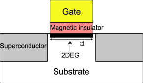
The schematic view of our SIFIS junction is shown in Fig. 1. The ferromagnetic part is effectively formed by a semiconductor two-dimensional electron gas (2DEG) underneath a ferromagnetic insulator and a gate voltage . The magnetic field induced by the ferromagnetic insulator causes the effective ferromagnetic correlation in 2DEG, the Zeeman energy of the electrons. And the Fermi wavevector of 2DEG (thus the phase state of the junction, as shown below) is controlled by .
To understand the phase state of the junction, we first ignore the charging energy of the junction. In this limit, the quasi-particle state of the SIFIS junction in Fig. 1 can be described by the Bogoliubov-de Gennes equation, BdeG
| (1) |
where is the coordinate along the junction direction, () is the electron-like (hole-like) component of the state, is the spin index, and . Here and for . The chemical potential equals to the Fermi energies of the superconductors and the ferromagnetic 2DEG, and . The Zeeman energy of electrons exists only in the ferromagnetic part, , where is the step function and is the length of the 2DEG. The superconducting pair potential is approximated to have a step form, , which is valid at low temperature . Here is the phase of the left (right) superconductor and is the critical temperature of the superconductors.
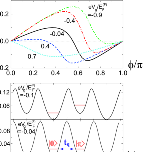
The phase state of the junction can be tuned by . In Fig. 2(a), we plot the Josephson current of the junction, calculated from the relation, . Here, is the Green function obtained from Eq. (1), is the phase difference, , and is the Matsubara frequency. In Fig. 2(b), we plot the potential energy, , obtained from . Here is the number operator of Cooper pairs satisfying . The ground state of the junction is determined by the local minima of the potential energy. We find that as varies, the sign of the Josephson current changes, i.e., there occurs the ground-state transition of the junction between the state , and the state . This behavior results from the facts that is tuned by and that the change of has the same effect as that of the length , since the 0- transition is controlled by the single variable . Radovic This gate-voltage operation has better controllability of the transition than the previous experimental ways where samples with different were used Kontos or temperature was tuned Sellier .
The parameters of a typical InAs 2DEG are used for the calculation. We use the Fermi energy Wildoer 10 meV and the effective g-factor Bjork . The magnetic field induced by a ferromagnetic insulator Vancura is about T. We choose 2 T for it, which gives 0.25 meV, i.e., . We choose the length of the 2DEG as m, which is shorter than the elastic mean free path ( m) Takayanagi of electrons in the 2DEG, so we ignore disorders. Under these parameters, the ground-state transition occurs around , where the two states, and , are degenerate; see Fig. 2. Note that a ferromagnetic insulator inducing weaker can cause the same - transition for a 2DEG with larger , as the transition is governed by the variable .
So far, the charging energy of the insulating barriers (I) has been ignored. We assume that it negligibly modifies . Then the Hamiltonian of the SIFIS junction is
| (2) |
where and is the junction capacitance. The first term is the charging energy and causes the tunneling between and . The tunneling gives rise to the quantum mechanical superposition of the two states when the two states are degenerate. The tunneling rate is estimated by using the WKB approximation, , where , , and in the harmonic potential approximation. For smaller , is larger. In usual superconducting qubits ChargeQ ; Mooij , F. The capacitance of superconductor/2DEG junction depends on the junction area, . Krasnov Here we set 1 fF, and estimate GHz.
The and states constitute a qubit. The qubit state is described by the superposition of and , and it is operated by the gate voltage applied to the ferromagnetic 2DEG at the degeneracy point. When an oscillating gate voltage with is applied, the qubit state is described by the Hamiltonian,
| (3) | |||||
since and linearly depend on around the degeneracy point. The Hamiltonian shows the Rabi oscillation between and with the period of , when is identical to the energy gap at the degeneracy point, . Ashhab The coupling strength is determined by junction parameters, and estimated as GHz for . This scheme has the merit that the operations take place at the optimal point, .
For a quantum computing the coupling of the qubits needs to be controllable and switchable. We propose a scalable scheme for qubit readout and tunable qubit coupling. In Fig. 3(a), two SIFIS and one SFS junctions form a loop, and the two SIFIS phase qubits, saying Qubit1 and Qubit2, are coupled due to the periodic boundary condition, . The resulting two-qubit state depends on the gate voltage applied to the SFS junction. When the gate voltage is adjusted such that the SFS junction is in the 0 () state, i.e., (), Qubit1 and Qubit2 are in a superposition of and ( and ). On the other hand, when the gate voltage is adjusted such that both the 0 and states are stable in the SFS junction, but need not be degenerate, the energy difference between the two SFS states causes the energy difference between the two-qubit states with ( and ) and those with ( and ).
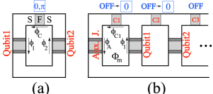
This coupling scheme has an important advantage that the coupling between qubits is tunable by the gate voltage applied on the SFS junction. The coupling energy comes from the energy difference between the states with ( and ) and those with ( and ). As the energy difference is tuned by the gate voltage applied to the SFS junction, one can change the sign as well as the strength of . When , the coupling is switched off effectively.
After two-qubit operations, the couplings between the qubits in Fig. 3(b) are switched off. Then the state of Qubit1 can be measured by using the left auxiliary SIFIS junction, as follows. One sets the gate voltages on C1 and on the auxiliary junction such that only the 0 state is stable in both the junctions, i.e., the state cannot be formed even at the excited levels. Then one turns on a small measuring external flux through the loop consisting of C1, Qubit1, and the auxiliary junction. Then, the direction of current along the loop is different for two states, and , of Qubit1. Yamashita06 Hence one measures Qubit1 by observing the direction of induced magnetic moment using a dc-SQUID Mooij . After the measurement of Qubit1, one can also detect Qubit2 by setting the gate voltages such that the coupling junctions C1 and C3 are switched off and that Qubit1 and C2 are in the 0 states. Here Qubit1 behaves as an auxiliary junction for Qubit2. In this way, all the qubits in the whole circuit can be measured sequentially.
In summary, we have proposed a new qubit in an SIFIS junction, and discussed a scalable scheme for qubit operation, measurement, and tunable and switchable two-qubit coupling. The qubit is based on the phase degree of freedom, and a single-qubit state and the two-qubit coupling are operated by gate voltage. Our scheme has an important merit that it is insensitive to the decoherence coming from the fluctuations of background charges and from magnetic microwave-pulse operations.
This work is supported by KRF (2005-070-C00055, 2006-331-C00118; TWN and HSS).
References
- (1) T. Yamamoto, Yu. A. Pashkin, O. Astafiev, Y. Nakamura, and J. S. Tsai, Nature 425, 941 (2003).
- (2) D. Vion, A. Aassime, A. Cottet, P. Joyez, H. Pothier, C. Urbina, D. Esteve, and M. H. Devoret, Science 296, 886 (2002).
- (3) I. Chiorescu, Y. Nakamura, C. J. P. M. Harmans, and J. E. Mooij, Science 299, 1869 (2003).
- (4) M. Steffen, M. Ansmann, R. C. Bialczak, N. Katz, E. Lucero, R. McDermott, M. Neeley, E. M. Weig, A. N. Cleland, and J. M. Martinis, Science 313, 1423 (2006).
- (5) A. I. Buzdin, L. N. Bulaevskii, and S. V. Panyukov, JETP Lett. 35, 178 (1982);
- (6) V. A. Oboznov, V. V. Bol’ginov, A. K. Feofanov, V. V. Ryazanov, and A. I. Buzdin, Phys. Rev. Lett. 96, 197003 (2006).
- (7) H. Sellier, C. Baraduc, F. Lefloch, and R. Calemczuk, Phys. Rev. Lett. 92, 257005 (2004).
- (8) T. Yamashita, K. Tanikawa, S. Takahashi, and S. Maekawa, Phys. Rev. Lett. 95, 097001 (2005).
- (9) T. Yamashita, S. Takahashi, and S. Maekawa, Appl. Phys. Lett. 88, 132501 (2006).
- (10) P. G. de Gennes, Superconductivity of Metals and Alloys (Benjamin, New York, 1966).
- (11) Z. Radović, L. Dobrosavljević-Grujić, and B. Vujiić, Phys. Rev. B 63, 214512 (2001);
- (12) J. W. G. Wildöer, C. J. P. M. Harmans, and H. van Kempen, Phys. Rev. B 55, R16013 (1997).
- (13) M. T. Björk, A. Fuhrer, A. E. Hansen, M. W. Larsson, L. E. Froberg, and L. Samuelson, Phys. Rev. B 72, R201307 (2005); C. Hermann and C. Weisbuch, Phys. Rev. B 15, 823 (1977).
- (14) T. Vančura, T. Ihn, S. Broderick, and K. Ensslin, W. Wegscheider, and M. Bichler, Phys. Rev. B 62, 5074 (2000).
- (15) H. Takayanagi, T. Akazaki, and J. Nitta, Phys. Rev. Lett. 75, 3533 (1995).
- (16) V. M. Krasnov, T. Golod, T. Bauch, and P. Delsing, Phys. Rev. B 76, 224517 (2007).
- (17) S. Ashhab, J. R. Johansson, A. M. Zagoskin, and F. Nori, Phys. Rev. A 75, 063414 (2007).