Photonic entanglement as a resource in quantum computation and quantum communication
Abstract
Entanglement is an essential resource in current experimental
implementations for quantum information processing. We review a
class of experiments exploiting photonic entanglement,
ranging from one-way quantum computing over quantum communication
complexity to long-distance quantum communication. We then propose
a set of feasible experiments that will underline the advantages
of photonic entanglement for quantum information processing.
I Introduction
Quantum entanglement Schrodinger35a has become an important
resource for many practical tasks in quantum information
processing such as quantum computing, quantum communication or
quantum metrology. From an early stage on, entanglement proved to
be an essential tool for quantum physics, both in theory and
experiment: early experimental realizations of entangled photon
pairs were used to demonstrate the quantum nature of polarization
correlations that can occur in decay
processes Wu_1950 ; Kocher_1967 , to confirm quantum
predictions of radiation theory and falsify semi-classical
models Clauser72 ; Clauser74 , or to test Bell’ s theorem and
exclude local realistic descriptions of the observed quantum
phenomena Bell64 ; Freedman72 ; Aspect82b ; Weihs98 . It followed
the discovery of information processing for quantum physics (and
vice versa), partly triggered by the introduction of quantum
cryptography Wiesner83 ; Bennett84 ; Ekert91 , and hence the
beginning of quantum information science, which has evolved to a
strongly expanding branch of science. Entanglement is a
fundamental resource for it, as a quantum channel in quantum
communication (e.g. for quantum state
teleportation Bennett93 ; Bouwmeester97 or quantum dense
coding Bennett92b ; Mattle96 ) or as computational resource.
Quantum computing with photons has recently experienced a new
boom by discovering the possibility of universal computing with
linear optics and measurements alone Knill00 . Although it
is still unclear what the minimal resource requirements for
optical quantum computing are, the number of required optical
elements per universal gate is constantly decreasing. Another
appealing feature of photonic quantum computing is the possibility
of gate times much faster
than in any other physical implementation to date.
In the following we will discuss new examples involving
experiments on entangled photons that underline the importance of
entanglement for quantum information processing. Section 2 starts
with an introduction to photonic one-way quantum computing, a new
approach that makes optimal use of entanglement as a resource. We
propose an experiment to achieve deterministic quantum computing,
a unique feature of the one-way quantum computer, by introducing
active corrections during the computation. Section 3 describes
experimental challenges and perspectives when exploiting
distributed entanglement for quantum networking tasks, in
particular long-distance quantum communication,
higher-dimensional quantum cryptography and quantum communication
complexity.
II Towards deterministic One-Way Quantum Computing with active Feed-Forward
Linear optical quantum computing (LOQC) is one of the promising
candidates for the physical realization of quantum computers. LOQC
employs photonic qubits as information carriers, which have the
immense advantage of suffering negligible decoherence and
providing high-speed gate operations. It was shown that linear
optics and projective measurements allow for essential nonlinear
interactions and eventually for scalable quantum
computing Knill00 . This has led to a flurry of research in
both theory and experiments. A recent and comprehensive overview
can be found in Kok_2005 . The intrinsic randomness of the
projective measurements in linear optics, however, only allows for
probabilistic gate operations, i.e., the gate operations are
successful only in a small fraction of the time. The other times
the outcomes need to be discarded. Although the gate success
probability increases with additional resources (optical elements
and/or ancilla photons), such schemes achieve nearly
deterministic gate operations only in the asymptotic regime of
infinite resources, which is experimentally infeasible. In
contrast, the one-way quantum computer model
Raussendorf01 ; Nielsen04b , an exciting alternative approach
to LOQC, allows the resource for the quantum computation to be
prepared offline prior to any logical operations. The
computational resource is a highly entangled state (the so-called
cluster state). Once the cluster state is prepared, the
computation proceeds deterministically, i.e. every
measurement produces a meaningful result, requiring only single
qubit measurements and feed-forward of the measurement result.
Feed-forward is the essential feature that makes one-way quantum
computing deterministic and can be seen as an active correction
of errors introduced by the randomness of measurement outcomes. We
will argue in the following that present state-of-the-art
technology allows for a demonstration of deterministic
one-way quantum computing by implementing this active feed-forward technique.
A cluster state is a network of entangled qubits and represents a
universal state for quantum computing. Universal means that any
quantum logic operation can be carried out on a sufficiently large
and appropriately structured cluster state. These states arise
when individual qubits are prepared in the superposition state
, where
denote the computational basis states, and
connected by applying a controlled-PHASE operation
with
between neighboring qubits, effectively
generating entanglement. Recent experiments succeeded in creating
cluster states with various
methods Walther05 ; Kiesel_2005 ; Zhang_2006 , including linear
optical realizations of simple controlled-PHASE
gates Langford_2005 ; Kiesel_2005b ; Okamoto_2005 .
Single qubit measurements are essential in cluster state quantum
computing. The shape of the cluster state and the nature of these
measurements, i.e. the order of measurements and the individual
measurement bases are determined by the desired algorithm. The
input state is always initialized as
. It is important to note that the entire information
of the input state is initially stored in the multi-particle
correlations of the cluster, with the individual physical qubits
being completely undefined and therefore not carrying any
information about the input state. In this sense, namely that
properties of individual subsystems are completely undefined, the
cluster state is a maximally entangled state. Well-known examples
include 2-qubit Bell states and 3-qubit GHZ states. Single qubit
measurements on the cluster processes the encoded input from one
qubit to another analogous to remote state preparation. In
principle, two basic types of single-particle measurements
suffice to operate the one-way quantum computer. Measurements in
the computational basis have the
effect of disentangling, i.e., removing the physical qubit
from the cluster. This leaves a smaller cluster state and thus
gives the ability to shape the cluster to the specific algorithm.
The measurements which perform the actual quantum information
processing are made in the basis
, where
with . For
simplicity, we will restrict our discussion on single-qubit gate
operations, i.e. measurements on linear cluster
states Walther05 . The argument can be generalized in a
straight-forward manner.
The choice of measurement basis determines the single-qubit
rotation, , followed
by a Hadamard operation, , on
the input state (, , , being
the Pauli matrices).
| (1) |
The order and choices of these measurements determine the unitary gates that are implemented and therefore the algorithm that is computed. Remember that input states are by construction always unless the cluster is part of a larger cluster state. Rotations around the z-axis can be implemented through the identity so that two consecutive measurements on a linear 3-qubit cluster can rotate the input state to any arbitrary output state on the Poincare-Sphere
| (2) |
Up until now, we have not incorporated the actual measurement result in our analysis. Eq. 1 only holds if the outcome of the measurement is as desired, say . Due to the intrinsic randomness of the quantum measurement, it happens with equal probability that the measurement yields the unwanted result . In that case, a well known Pauli-error () is introduced in the computation, so that the single measurement in basis rotates the qubit to:
| (3) |
Obviously, by adapting the measurement bases of subsequent measurements, these errors can be eliminated. In the following, let us consider the general case of a single-qubit operation by taking into account the feed-forward rules. If we choose consecutive measurements in bases and on physical qubits 1 and 2 of a 3-qubit cluster, then we rotate the encoded input qubit to the output state
| (4) |
which is stored on qubit 3. The measurement outcome, , on the physical qubit determines the measurement basis for the succeeding qubit and indicates any introduced Pauli errors that have to be compensated for. This idea can schematically be depicted as a circuit diagram:
Single wires represent quantum channels, while double lines denote classical communication. The circles in front of the measurement meters show the measurement basis. No error correction is required for the specific case where the outcomes of the first and second qubit are and hence, as expected, . However, if the outcome of the second qubit is () the measurement basis of the third qubit has to be changed from to and finalized by a Pauli error correction, i.e. on the output qubit, to get the desired output of the computation. This yields Similar corrections are required in the cases when the third qubit’s outcome is () and hence . Finally, if an unwanted projection occurs to both qubits, (), two Pauli errors, and , have to be compensated for on qubit 3 yielding . This is summarized in Table 1.
Experimentally, feed-forward can only be achieved by recording both measurement outcomes simultaneously, . The recent photonic realization of a one-way quantum computer Walther05 employed single-port polarizers, which are, although sufficient to demonstrate the working principle, not suited for this purpose. Simultaneous recording of the measurement results can be achieved with polarizing beamsplitters (PBSs), preceded by half- and quarter-wave plates to chose arbitrary measurement bases. The basis of the measurements can be adapted by employing fast-switching and low-loss electro-optical modulators (EOMs), which, depending on the applied voltage, change the photon’s state of polarization. Analogously, error-correction can be performed on the output qubit if the EOMs are aligned to apply and rotations, respectively.
In an experimental implementation of this scheme, the individual
photonic qubits must be delayed just long enough so that the
classical feed-forward process can be carried out, i.e., that an
individual outcome can adapt the measurement basis for the next
measurement. The most rudimentary ”quantum memory” that can be
used for such purpose is a single-mode fiber of a specific length,
which has negligible photon loss over moderate distances. Every
single feed-forward process includes detection of the photon,
processing of the measurement result and finally switching of the
modulator to adapt the measurement basis in real time and/or
performing error correction on the output qubit. A major advantage
of optical quantum computation is the achievable high speed of the
gate operation. Various types of EOMs achieve low-loss and high
contrast switching with fidelities above 99%. Switching times are
well below 100 ns when combined with custom built drivers and such
devices have successfully been implemented in early
demonstrations of feed-forward
control Ursin04 ; Giacomini02 ; Pittman_2002 . Currently
available logic boards and single-photon detectors have response
times of around 10 ns and 30 ns, respectively, so that
feed-forward cycles of less than 150 ns seem experimentally
feasible. This time-scale corresponds to a single-mode fiber delay
line of approximately 30 m. A gate time of 150-300 ns for one
computational step is, to our best knowledge, about three orders
of magnitude faster than achievable in other physical
realizations of quantum computers such as in
ion-traps Riebe04 ; Barrett04 or in NMR Lieven_2001 .
Based on our recent successful demonstration of one-way quantum computing Walther05 , a proof-of-concept demonstration of deterministic quantum computing, i.e. implementation of active feed-forward and error-correction in real time, on a 4-photon cluster state is certainly feasible. Conceptually, this would present a crucial step towards realizing scalable optical quantum computing, showing that it is indeed possible to build a deterministic quantum computer which uses both entanglement and the intrinsically random measurement outcomes as an essential feature.
III Entanglement as communication channel – Quantum Communication
III.1 Distributed Computing: Entanglement for Quantum Communication Complexity
Although entanglement on its own cannot be used for communication, it surprisingly can produce effects as if information had been transferred. In a communication complexity problem, separated parties performing local computations exchange information in order to accomplish a globally defined task, which is impossible to solve single-handedly Yao1 ; Yao2 . Remarkably, if the parties share entanglement the required information exchange in the communication complexity problem can be reduced Cleve1997 or even eliminated Buhrman1997 . Such a reduction of communication complexity might be important in future for speeding up distributed computations, e.g. within very large scale integration (VLSI) circuits.
Here we will determine the experimental requirements for quantum communication complexity protocols to outperform their classical counterparts in solving certain types of problems. This will include determination of the required minimal visibility and the detection efficiency for the advantage. The type of the problems considered here is as follows. There are separated partners who receive local input data such that they know only their own data and not those of the partners. The goal is for all of them to determine the value of a function . Before they start the protocol, they are allowed to share classically correlated random strings or quantum entanglement. If only a restricted amount of communication is allowed, we ask the questions: What is the highest possible probability for the parties to arrive at the correct value of the function? We refer to this probability as ”success rate” of the protocol.
Recently, it has been realized that communication complexity problems are tightly linked to Bell’s theorem Bell64 . On the basis of this insight, quantum protocols are developed that exploit entanglement between qubits Brukner2004 , qutrits Brukner02 and higher dimensional states Brukner2003 . The crucial idea is that every classical protocol can be simulated by a local realistic model and thus its success rate is limited by the Bell-type inequalities Brukner2004 . In contrast, the success rate of quantum protocols—which make use of entangled states—can exceed these limits, since entangled states are at variance with local realism. More precisely, for every Bell’s inequality—even those which are not yet known—there exists a communication complexity problem, for which a protocol assisted by states which violate the inequality has a higher success rate than any classical protocol. Violation of Bell’s inequalities is thus the necessary and sufficient condition for quantum protocols to beat the classical ones.
Consider the general Bell’s inequality for correlation functions
| (5) |
Here is a real function, is a bound imposed by local realism and is the correlation function for measurements on particles, which involve, at each local measurement station , two alternative dichotomic observables, parameterized here by and . In Ref. Brukner2004 it was shown that this Bell’s inequality puts limits on the success rate in computation of certain two-valued functions with the inputs or comment . The execution of the protocol is successful when all parties arrive at the correct value of .
The most interesting case found is for , odd and for which the success probability of classical solutions cannot be larger than
| (6) |
whereas a quantum protocol solves the problem with certainty, i.e. comment . This implies that in the limit of very large one has , which is not better than if the partners simply agree beforehand to choose all the same (random) value for the value of the function.
Without going into the details of the protocols we mention here that both in the classical and quantum case the partners give all the same value for their guess of the value of the function . (This value is obtained as a product of locally produced values , where is broadcasted by party . See Brukner2004 ; comment for details.) The important difference is that in a quantum protocol this value is obtained from local results of the Bell experiment for parties, whereas in a classical protocol it is obtained from the results of local (classical) operations assisted with classical correlations. The maximal success rate of of the quantum protocol is obtained using the Greenberger-Horne-Zeilinger state GHZ89 .
For the quantum protocol to beat the best classical one we need a success higher than . We now analyze detectors with finite detection efficiency and non-maximal visibility due to experimental imperfections as modeled by an admixture of white noise to the perfect state: .
With a finite detector efficiency , the partners obtain perfect quantum correlations in of the cases and proceed with the quantum protocol with the success rate . When their detectors fail, the partners must agree on a procedure. They are not allowed to communicate the failure, as this would consist of further bits of communication between the parties, and the allowed communication is restricted. The most effective way for a partner is to proceed with the best classical protocol in case her/his detector fails. It is assumed that there are no experimental constraints for classical protocols as they are based on manipulating and detecting classical systems (e.g. balls or pencils), which could be done with very high efficiency.
Whenever all detectors fail, which happens in of the cases, the partners will obtain the best classical success rate . In the cases when some of the detectors fail and the rest fire, the partners whose detectors fail would start the best classical protocols, whereas those whose detectors fire proceed with the quantum protocol. Since the two protocols are completely independent, the success rate is not better than the probability that all partners give the same but random guess for the value of the function. In the rest of the cases, all detectors fire measuring white noise, which again leads to the success as for the random guess. Thus, in of the cases the success rate is .
Taking all this into account, the condition for a higher-than-classical success rate is:
| (7) |
A similar analysis for the special case of and special function was given by Galvao in Ref. Galvao2002 . In Figure 1 we show the region in the parameter space of , and that guarantees a higher-than-classical success rate. Taking for the detector efficiency and visibility , one obtains for the minimal number of photons in the entangled state, which is well within the scope of current technology. Recently, a quantum communication complexity protocol based on the sequential transfer of a single qubit Galvao2002 was experimentally implemented and its advantage over the classical counterpart was shown in the presence of the imperfections of a state-of-the-art set-up Trojek2005 . It could therefore be expected in near future that entanglement-based quantum communication complexity protocols will become comparable to quantum key distribution, the only commercial application of quantum information science so far.
III.2 Distributed Entanglement in Higher Dimension: Entangled Qutrit Quantum Cryptography
All Quantum Cryptography experiments performed so far were based
on two-dimensional quantum systems (qubits). However, the usage of
higher-dimensional systems offers advantages such as an increased
level of tolerance to noise at a given level of security and a
higher flux of information compared to the qubit cryptography
schemes.
In a recent experiment we produced two identical keys using, for
the first time, entangled trinary quantum systems (qutrits) for
quantum key distribution Groeblacher2006 . The advantage of
qutrits over the normally used binary quantum systems is an
increased coding density and a higher security margin of 22%
(instead of ca. 15%). The qutrits are encoded into the orbital
angular momentum of photons, namely Laguerre-Gaussian modes with
azimuthal index and , respectively. The orbital
angular momentum is controlled with static phase holograms. In an
Ekert-type protocol the violation of a three-dimensional Bell
inequality verifies the security of the generated keys. A key is
obtained with a qutrit error rate of approximately 10%. The
security of this key is ascertained by the violation of the Bell
inequality, with . In contrast to the
polarization degree of freedom, in principle there is no
limitation on the dimension of the two-photon entanglement with
orbital angular momentum and therefore an extension of the qutrit
to a more general qudit case is feasible. This opens up a new
class of experiments with higher dimensional entanglement.
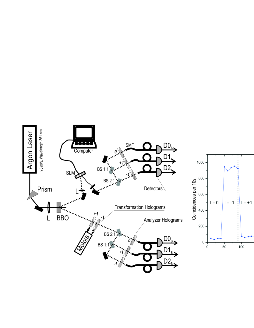
Spatial light modulators (SLM) promise a fascinating new experimental approach for working with the orbital angular momentum of photons. The main idea is to use the SLM for applying computer calculated holograms to the entangled photons (see Fig. 2) instead of static phase plates. Thereby we gain huge experimental flexibility, since we are now able to superimpose several optical elements such as lens configurations, mirrors and phase singularity onto one active phase element, and fine tune the holograms simply by adjusting the parameters in the calculation. This will open up possibilities of further study of three dimensional entanglement (or more dimensions), which is an area with many unknown features. A first successful demonstration of this method is shown in Figure 2 where we analyzed the correlation of entangled photons, where the orbital angular momentum of one of the photons is transformed via the SLM.
III.3 Distributed Entanglement: Long Distance Quantum Communication & Quantum Networking
There is a range of unique
applications emerging if several users share entangled particles,
such as quantum
cryptography Bennett84 ; Ekert91 ; Jennewein00b ; Naik00 ; Tittel00 ,
quantum teleportation Bennett93 ; Bouwmeester97 , quantum
dense coding Bennett92b ; Mattle96 or communication
complexity (see previous section). Clearly it is an important
prerequisite to be able to establish networks of quantum
communication, similar to what classical communication networks
do. It is particularly desirable to establish entanglement
between several users, with a very flexible network hierarchy.
For example, two users who wish to share entangled particles just
call their network operator, who performs the necessary settings
to accomplish this task. Likewise, if three users wish to share
GHZ-states, again the network operator performs the required
operations for this task.
Fortunately, quantum physics allows us to perform these tasks, if
the several users initially share entangled particles with a
central network operator. Utilizing the procedure known as
entanglement swapping Zukowski95 ; Jennewein02 , the
generalization of quantum teleportation, the operator may simply
swap the entanglement between the particles entangled with two
different users, such that finally the particles of the two users
get entangled. The operations that the central node (operator)
must perform are projection measurements onto the desired
entangled state. Since the particles originally have no relation,
the projective measurement will give a random result, which must
be communicated to the users, so they can use the entangled
particles. Entanglement swapping can in principle be generalized
to arbitrary quantum network sizes if the network operator
performs the swapping operations (i.e. projections on to
Bell-states, GHZ-states), depending on which users wish to
communicate. This is at the heart of a quantum
repeater Briegel98 , which additionally makes use of
entanglement purification Bennett96 ; Pan03b and quantum
memories to faithfully transmit entanglement over arbitrary
distances. Important experimental progress has been made along
this line, for example by demonstrating quantum teleportation
over long distances Ursin04 or by realizing non-classical
interference of photons from completely independent photon
sources Kaltenbaek2006 .
In the future, the use of satellite-based technology could
provide the means for distribution of quantum signals even on a
global scale Nordholt02 ; Rarity02 ; Aspelmeyer03b . These
schemes will involve sources for entangled photons onboard
satellites, which are sent via telescopes to other satellites as
well as optical earth-based ground stations. The principles of
this concept, free-space quantum communication, have been
demonstrated in various experiments both for faint-pulse
systems ´Hughes02 ; Rarity_2001 ; kurtsiefer02 and for
entangled photons Aspelmeyer03 ; Resch05 ; Peng05 ; Ursin_2006 .
The current distance record has been only recently achieved in a
144 km inter-island link using entangled
photons Ursin_2006 . These result are very promising for
entanglement-based free-space quantum communication in
high-density urban areas and even for large distances. It is also
encouraging for optical quantum communication between ground
stations and satellites since the length of our free-space link
exceeds the atmospheric
equivalent.
The progress of this huge research program of extending quantum
communication to Space is advancing and is taking on more momentum
continuously. In mid 2005 we have received the official positive
response to our proposal to the ELIPS-2 announcement for
opportunity, by the European Space Agency (ESA), describing our
experiment called ”Quantum entanglement for Space experiments”,
Space-QUEST, in full detail. The clear aim of our proposed
experiment is to place an entangled photon source on-board the
ISS and send the two photons towards two receiving ground
stations. This will allow performing fundamental experiments,
since the entangled photons can be separated by up to 1500 km
distance hence providing a significant enlargement of the size of
a quantum state possible on ground. Furthermore, the experiment
allows demonstrations of quantum communication applications at a
global scale, which is clearly not feasible with ground based
systems. Presently we are working together with scientific and
industrial partners on further refinements of the planned
systems, as well as with funding agencies to reserve the
resources for this large-scale experiment. In particular, we have
performed a design study together with Contraves AG (CH) for a
quantum communication terminal based on existing laser
communication terminals, to be placed on the International Space
Station Pfennigbauer05 . The designed platform contains all
optical, laser and electronic components required for the quantum
terminal operation. This system is based on the OPTEL25 optical
terminal, from Contraves AG (CH), designed for inter-satellite
laser communication. In addition we are performing
proof-of-concept experiments over 144 km using an inter-island
link between La Palma and Teneriffe.
A very interesting approach, alternative to the ISS system, is to implement quantum communication uplinks from ground to satellites. This scheme is particularly interesting, as the technical complexity of the Space-based receiver is significantly simpler than for the full quantum communication transmitter. Thereby the technical difficulty is transferred to the ground segment, which is clearly a well available environment. The main technical difficulty is the implementation of an adaptive optics system capable of pre-compensating the wave front distortion that the uplink beam will experience as it traverses the atmosphere.
If only one receiver in Space is implemented, this scheme allows
quantum communication, such as renewing keys for the
communication with satellites via quantum cryptography, or the
key exchange between separate ground stations, by joining up the
successive keys. If two receivers are realized, they would allow
performing also fundamental tests of quantum entanglement over
huge distances, and also with high relative velocities between
the observers Kaltenbaek04a . When the receiver satellite is
realized as a double-receiver unit, it will allow to combine
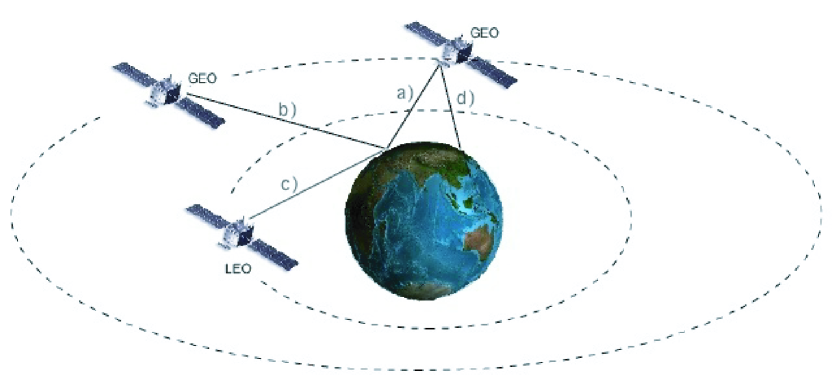
uplinks a) and d) of Fig. 3 and perform quantum
entanglement swapping for these photons, which will be an
important step towards global quantum communication networks by
distributing entanglement. The most critical technology is the
required adaptive optics for reducing the ”shower curtain” effect
of the atmosphere. A ground-to-Space link suffers much stronger
from atmospheric induced beam deviation, since the errors are
induced at the beginning of the beam path. As a consequence, the
transmitter on the ground must (pre-)compensate the distortion of
the transmitted light beam in order to minimize the spotsize
received at the satellite.
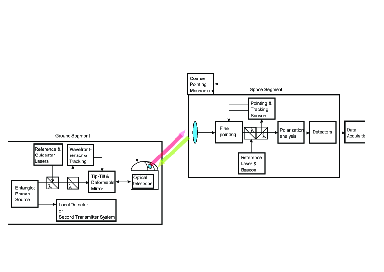
The advantage of this scenario is that the main technological
difficulties are transferred to the ground segment, whereas the
Space-segment is a somewhat simple receiver. The key
technological elements at the ground based transmitter stations
are (Fig. 4): (1) The source of entangled photons:
since placed on the ground, the limits on the size, power, and
stability of a source are highly relaxed. This would allow using
a down conversion source pumped by a high power solid laser (e.g.
Nd-YAG) laser, which already today produces high quality
entangled photons at a very high rate (5 M pairs/s). (2) High
quality transmitter telescopes: there are several suitable
optical ground stations available with apertures between 0.5 –
1.5 m diameter and diffraction limited quality, which offer the
ability to track low flying satellites. (3) Adaptive optics: This
is the crucial technology required for achieving link distances
of several thousands of km. Thereby the active wavefront
transformation will precompensate the wavefront distortion that
the beam of photons will experience when traveling through the
atmosphere. This technology is still in a laboratory status, and
has yet to be applied to the specific needs of quantum
communication. Since this technology could be utilize on the
ground segment the technology can be realized at the highest
possible level available at the time of the experiments.
The key technological elements at the satellite based receiver
are (Fig. 4): (1) Receiver telescope: the optical
quality of the receiving telescope must not be diffraction
limited, if the field of view (FOV) of the receiver is
sufficiently large. This is finally limited by the diameter of
the detectors. The telescopes must be motorized, and also employ
a fine-pointing mechanism for keeping up the alignment with the
transmitter telescope on ground. The tracking is performed with
the signals measured from reference lasers operating at a
separate wavelength. (2) Analysis of the photons: the polarization
of the photons must be analyzed in two different bases, such as
horizontal-vertical and diagonal linear polarization. This can be
accomplished with a combination of a symmetric beam splitter and
polarizing beam splitters in each output arm. In addition,
spectral filtering of the photons must be utilized in order to
suppress the background light. (3) Detection of the photons: The
received photons are focused on single photon detectors.
Depending on the final choice of wavelength, the presently best
single photon detection is achieved with silicon-avalanche photo
diodes (Si-APD). (4) Acquisition and processing of the detection
events: the detection events must be recorded as time-tags, and
stored on the satellite. The data must be sent to the ground for
further processing.
IV Conclusion
In summary, we have introduced and reviewed some recent experimental progress in the understanding of photonic quantum entanglement as a resource for quantum information processing. We have also provided an outlook onto future experiments that should be feasible with current technology and that will further highlight the distinctive role of entanglement. Besides the impressive achievements in laboratories all over the world there remain fascinating challenges for the future ranging from the interfacing of photons to scalable and durable architectures, i.e. including quantum memories, over the faithful production and characterization of multipartite entangled states of significant particle number to the realization of a full scale quantum repeater.
Acknowledgements.
We thank J. Kofler for valuable discussions. We acknowledge financial support by the FWF Austrian Science Fund, SFB project P06, the European Commission under the Integrated Project Qubit Applications QAP funded by the IST Directorate as contract number 015846, the ARO-funded U.S. Army Research Office Contract No. W911NF-05-0397 and the City of Vienna.References
- (1) E. Schrödinger, “Die Gegenwärtige Situation in der Quantenmechanik,” Naturwissenschaften 23, 807–812; 823–828; 844–849 (1935).
- (2) C. S. Wu and I. Shaknov, “The angular correlation of annihilation radiation,” Phys. Rev. 77, 136 (1950).
- (3) C. A. Kocher and E. D. Commins, “Polarization correlation of phootns emitted in an atomic cascade,” Phys. Rev. Lett. 18, 575–577 (1967).
- (4) J. F. Clauser, “Experimental Limitations to the Validity of Semiclassical Radiation Theories,” Phys. Rev. A 6, 49–54 (1972).
- (5) J. F. Clauser, “Experimental distinction between the classical and quantum field-theoreti predictions for the photoelectric effect,” Phys. Rev. D 9, 853–860 (1974).
- (6) J. S. Bell, “On the Einstein Podolsky Rosen Paradox,” Physics 1, 195–200 (1964).
- (7) S. J. Freedman and J. F. Clauser, “Experimental Test of Local Hidden-Variable Theories,” Phys. Rev. Lett. 28, 938–941 (1972).
- (8) A. Aspect, J. Dalibard, and G. Roger, “Experimental Test of Bell’s Inequalities Using Time- Varying Analyzers,” Phys. Rev. Lett. 49, 1804–1807 (1982).
- (9) G. Weihs, T. Jennewein, C. Simon, H. Weinfurter, and A. Zeilinger, “Violation of Bell’s Inequality under Strict Einstein Locality Conditions,” Phys. Rev. Lett. 81, 5039–5043 (1998).
- (10) S. Wiesner, “Conjugate coding,” Sigact News 15, 78–88 (1983).
- (11) C. H. Bennett and G. Brassard, “Quantum cryptography: Public Key Distribution and coin-tossing,” Proceedings of IEEE International Conference on Computers, Systems and Signa Processing, Bangalore, India pp. 175–179 (1984).
- (12) A. K. Ekert, “Quantum Cryptography Based on Bell’s Theorem,” Phys. Rev. Lett. 67, 661–663 (1991).
- (13) C. H. Bennett, G. Brassard, C. Crépeau, R. Jozsa, and A. P. an W. K. Wootters, “Teleporting an unknown quantum state via dual classical and Einstein-Podolsky-Rose channels,” Phys. Rev. Lett. 70, 1895–1899 (1993).
- (14) D. Bouwmeester, J.-W. Pan, K. Mattle, M. Eibl, H. Weinfurte, and A. Zeilinger, “Experimental Quantum Teleportation,” Nature 390, 575–579 (1997).
- (15) C. H. Bennett and S. J. Wiesner, “Communication via One- and Two-Particle Operators on Einstein-Podolsky-Rose States,” Phys. Rev. Lett. 69, 2881–2884 (1992).
- (16) K. Mattle, H. Weinfurter, P. G. Kwiat, and A. Zeilinger, “Dense Coding in Experimental Quantum Communication,” Phys. Rev. Lett. 76, 4656–4659 (1996).
- (17) E. Knill, R. Laflamme, and G. Milburn, “A Scheme for Efficient Quantum Computation with Linear Optics,” Nature 409, 46–52 (2000).
- (18) P. Kok, W. Munro, K. Nemoto, T. Ralph, J. P. Dowling, and G. Milburn, “Review article: Linear optical quantum computing,” quant-ph/0512071 (2005).
- (19) R. Raussendorf and H. J. Briegel, “A One-Way Quantum Computer,” Phys. Rev. Lett. 86(22), 5188–5191 (2001).
- (20) M. A. Nielsen, “Optical quantum computation using cluster states,” Phys. Rev. Lett. 93, 040,503 (2004).
- (21) P. Walther, K. J. Resch, T. Rudolph, E. Schenck, H. Weinfurter, V. Vedral, M. Aspelmeyer, and A. Zeilinger, “Experimental one-way quantum computing,” Nature 434, 169–176 (2005).
- (22) N. Kiesel, C. Schmid, U. Weber, G. Toth, O. Gühne, R. Ursin, and H. Weinfurter, “Experimental Analysis of a Four-Qubit Photon Cluster State,” Phys. Rev. Lett. 95, 210,502 (2005).
- (23) A.-N. Zhang, C.-Y. Lu, X.-Q. Zhou, Y.-A. Chen, Z. Zhao, T. Yang, and J.-W. Pan, “Experimental construction of optical multiqubit cluster states from Bell states,” Phys. Rev. A 73, 022,330 (2006).
- (24) N. K. Langford, T. J. Weinhold, R. Prevedel, K. J. Resch, A. Gilchrist, J. L. O’Brien, G. J. Pryde, and A. G. White, “Demonstration of a Simple Entangling Optical Gate and Its Use in Bell-State Analysis,” Phys. Rev. Lett. 95, 210,504 (2005).
- (25) N. Kiesel, C. Schmid, U. Weber, R. Ursin, and H. Weinfurter, “Linear Optics Controlled-Phase Gate Made Simple,” Phys. Rev. Lett. 95, 210,505 (2005).
- (26) R. Okamoto, H. F. Hofmann, S. Takeuchi, and K. Sasaki, “Demonstration of an Optical Quantum Controlled-NOT Gate without Path Interference,” Phys. Rev. Lett. 95, 210,506 (2005).
- (27) R. Ursin, T. Jennewein, M. Aspelmeyer, R. Kaltenbaek, M. Lindentha, P. Walther, and A. Zeilinger, “Quantum teleportation across the Danube,” Nature 430, 849 (2004).
- (28) S. Giacomini, F. Sciarrino, E. Lombardi, and F. D. Martini, “Active teleportation of a quantum bit,” Phys. Rev. A 66, 030,302(R) (2002).
- (29) T. B. Pittman, B. C. Jacobs, and J. D. Franson, “Demonstration of feed-forward control for linear optics quantum computation,” Phys. Rev. A 66, 052,305 (2002).
- (30) M. Riebe, H. Häffner, C. F. Roos, W. Hänsel, J. B. an G. P.T. Lancaster, T. W. Körber, C. Becher, F. S.-K. an D. F. V. James, and R. Blatt, “Quantum teleportation with atoms,” Nature 429, 734–737 (2004).
- (31) M. D. Barrett, J. Chiaverini, T. Schaetz, J. Britton, W. M. Itano, J. D. Jost, E. Knill, C. Langer, D. Leibfried, R. Ozeri, and D. J. Wineland, “Quantum teleportation with atomic qubits,” Nature 429, 737–739 (2004).
- (32) L. M. Vandersypen, M. Steffen, G. Breyta, C. S. Yannoni, M. H. Sherwood, and I. L. Chuang, “Experimental realization of Shor’s quantum factoring algorithm using nuclear magnetic resonance,” Nature 414, 883–887 (2001).
- (33) A. C.-C. Yao, in Proceedings of the 11th Annual ACM Symposium on Theory of Computing, pp. 209–213 (1979).
- (34) A. C.-C. Yao, in Proceedings of the 34th Annual IEEE Symposium in Foundations of Computer Science, pp. 352–361 (1993).
- (35) R. Cleve and H. Buhrman, Phys. Rev. A 56, 1201–1204 (1997).
- (36) H. Buhrman, R. Cleve, and W. van Dam, e-print quant-ph/9705033 (1997).
- (37) C. Brukner, M. Zukowski, J.-W. Pan, and A. Zeilinger, Phys. Rev. Lett. 92, 127,201 (2004).
- (38) C. Brukner, M. Zukowski, and A. Zeilinger, “Quantum communication complexity protocol with two entangled qutrits,” Phys. Rev. Lett. 89, 197,901 (2002).
- (39) C. Brukner, T. Paterek, and M. Zukowski, Int. J. Quant. Inf. 1, 519–525 (2003).
- (40) Strictly speaking, in communication complexity problems of Ref. Brukner2004 each party receives two one-bit inputs and their goal is to compute a function of the form . The values of the function and the are . Each party is allowed to broadcast only one bit of information (denoted as ). For the present analysis the existence of inputs is not of importance and is ommited here. See Ref. Brukner2004 for details.
- (41) D. M. Greenberger, M. A. Horne, and A. Zeilinger, “Going beyond Bell’s Theorem,” in Bell’s Theorem, Quantum Theory, and Conceptions of the Universe, M. Kafatos, ed., p. 69 (Kluwer, Dordrecht, 1989).
- (42) E. F. Galvao, “Feasible quantum communication complexity protocol,” Phys. Rev. A 65, 12,318 (2002).
- (43) P. Trojek, C. Schmid, M. Bourennane, Č. Brukner, M. Zukowski, and H. Weinfurter, “Experimental quantum communication complexity,” Phys. Rev. A 72, 50,305(R) (2005).
- (44) S. Gröblacher, T. Jennewein, A. Vaziri, G. Weihs, and A. Zeilinger, “Experimental quantum cryptography with qutrits,” N. J. Phys. 8, 75 (2006).
- (45) T. Jennewein, C. Simon, G. Weihs, H. Weinfurter, and A. Zeilinger, “Quantum Cryptography with Entangled Photons,” Phys. Rev. Lett. 84, 4729–4732 (2000).
- (46) D. S. Naik, C. G. Peterson, A. G. White, A. J. Berglund, and P. G. Kwiat, “Entangled State Quantum Cryptography: Eavesdropping on the Ekert Protocol,” Phys. Rev. Lett. 84, 4733–4736 (2000).
- (47) W. Tittel, J. Brendel, H. Zbinden, and N. Gisin, “Quantum Cryptography Using Entangled Photons in Energy-Time Bell States,” Phys. Rev. Lett. 84, 4737–4740 (2000).
- (48) M. Zukowski, A. Zeilinger, and H. Weinfurter, “Entangling Photons Radiated by Independent Pulsed Sources,” in Fundamental Problems in Quantum Theory: A Conference Held in Honor of Professo John A. Wheeler, D. M. Greenberger and A. Zeilinger, eds., Annals of the New York Academy of Sciences, pp. 91–102 (New York Academy of Sciences, New York, 1995).
- (49) T. Jennewein, G. Weihs, J.-W. Pan, and A. Zeilinger, “Experimental Nonlocality Proof of Quantum Teleportation and Entanglemen Swapping,” Phys. Rev. Lett. 88, 17,903 (2002).
- (50) H.-J. Briegel, W. Dür, J. I. Cirac, and P. Zoller, “Quantum Repeaters: The Role of Imperfect Local Operations in Quantum Communication,” Phys. Rev. Lett. 81, 5932–5935 (1998).
- (51) C. H. Bennett, G. Brassard, S. Popescu, B. Schumacher, J. A. Smolin, and W. K. Wootters, “Purification of Noisy Entanglement and Faithful Teleportation via Nois Channels,” Phys. Rev. Lett. 76, 722–725 (1996).
- (52) J.-W. Pan, S. Gasparoni, R. Ursin, G. Weihs, and A. Zeilinger, “Experimental Entanglement Purification,” Nature 423, 417–422 (2003).
- (53) R. Kaltenbaek, B. Blauensteiner, M. Zukowski, M. Aspelmeyer, and A. Zeilinger, “Experimental interference of independent photons,” Phys. Rev. Lett. 96, 0240,502 (2006).
- (54) J. E. Nordholt, R. Hughes, G. L. Morgan, C. G. Peterson, and C. C. Wipf, “Present and Future Free-Space Quantum Key Distribution,” in Free-Space Laser Communication Technologies XIV, vol. 4635 of Proceedings of SPIE, p. 116 (SPIE, 2002).
- (55) J. G. Rarity, P. R. Tapster, P. M. Gorman, and P. Knight, “Ground to satellite secure key exchange using quantum cryptography,” New Journal of Physics 4, 82 (2002).
- (56) M. Aspelmeyer, T. Jennewein, M. Pfennigbauer, W. R. Leeb, and A. Zeilinger, “Long-Distance Quantum Communication With Entangled Photons Using Satellites,” IEEE J. Sel. Top. Quant. Elec. 9, 1541–1551 (2003).
- (57) R. J. Hughes, J. E. Nordholt, D. Derkacs, and C. G. Peterson, “Practical free-space quantum key distribution over 10 km in daylight an at night,” N. J. Phys. 4, 43 (2002).
- (58) J. Rarity, P. Tapster, and P. Gorman, “Secure free-space key exchange to 1.9 km and beyond,” J. Mod. Opt. 48, 1887–1901 (2001).
- (59) C. Kurtsiefer, P. Zarda, M. Halder, H. Weinfurter, P. Gorma, P. Tapster, and J. Rarity, “A Step Towards Global Key Distribution,” Nature 419, 450 (2002).
- (60) M. Aspelmeyer, H. R. Böhm, T. Gyatso, T. Jennewein, R. Kaltenbae, M.Lindenthal, G. Molina-Terriza, A. Poppe, K. Resch, M. Taraba, R. Ursin, P. Walther, and A. Zeilinger, “Long-Distance Free-Space Distribution of Quantum Entanglement,” Science 301, 621–623 (2003).
- (61) K. Resch, M. Lindenthal, B. Blauensteiner, H. Böhm, A. Fedrizzi, C. Kurtsiefer, A. Poppe, T. Schmitt-Manderbach, M. Taraba, R. Ursin, P. Walther, H. Weier, H. Weinfurter, and A. Zeilinger, “Distributing entanglement and single photons through an intra-city, free-space quantum channel,” Optics Express 13, 202–209 (2005).
- (62) C.-Z. Peng, T. Yang, X.-H. Bao, J. Zhang, X.-M. Jin, F.-Y. Feng, B. Yang, J. Yang, J. Yin, Q. Zhang, N. Li, B.-L. Tian, and J.-W. Pan, “Experimental Free-Space Distribution of Entangled Photon Pairs Over 13 km: Towards Satellite-Based Global Quantum Communication,” Phys. Rev. Lett. 94, 150,501 (2005).
- (63) R. Ursin, F. Tiefenbacher, T. Schmitt-Manderbach, H. Weier, T. Scheidl, M. Lindenthal, B. Blauensteiner, T. Jennewein, J. Perdigues, P. Trojek, B. Oemer, M. Fuerst, M. Meyenburg, J. Rarity, Z. Sodnik, C. Barbieri, H. Weinfurter, and A. Zeilinger, “Free-Space distribution of entanglement and single photons over 144 km,” quant-ph/0607182 (2006).
- (64) M. Pfennigbauer, W. Leeb, G. Neckamm, M. Aspelmeyer, T. Jennewein, F. Tiefenbacher, A. Zeilinger, G. Baister, K. Kudielka, T. Dreischer, and H. Weinfurter, “Accommodation of a quantum communication transceiver in an optical terminal (ACCOM),” Tech. Rep. ESTEC/Contract No. 17766/03/NL/PM, European Space Agency (ESA) (2005).
- (65) R. Kaltenbaek, M. Aspelmeyer, T. Jennewein, C. Brukner, M. Pfennigbaue, W. R. Leeb, and A. Zeilinger, “Proof-of-Concept Experiments for Quantum Physics in Space,” in Quantum Communications and Quantum Imaging, R. Meyers and Y. Shih, eds., vol. 5161, pp. 252–268 (2003).
- (66) M. Stütz, Master’s thesis, University of Vienna (2006).
List of Figure Captions
Fig. 1. The dotted volume indicates the region where the visibility , detection efficiency and number of partners allow for a multi-party quantum communication complexity protocol which is more efficient than any classical one for the same task. The volume corresponds to that given by inequality (7).
Fig. 2. (Left) Setup demonstrating the photon manipulation by a spatial light modulator (SLM) stuetz06 . The photon pairs produced by down conversion in a barium borate (BBO crystal) are entangled in their orbital angular momentum, represented by the Laguerre-Gaussian modefunctions. The mode index corresponds to the orbital angular momentum of each photon. The transformation between different modes is performed by passing the photons through phase diffraction gratings containing a phase singularity, which is generated by the SLM. (Right) Demonstrating the transformation of the photon by the computer-calculated hologram on the SLM. The coincidence between the detectors and is shown. Due to the initial correlation between the photons there are little coincidence counts, unless the SLM performs a transformation. This clearly demonstrates that we are able to manipulate the orbital angular momentum of the entangled photon by means of the computer-generated hologram.
Fig. 3. Quantum communication links realized as uplinks from ground to Space. Entangled photons are generated on ground, and sent towards one or more Space-based receivers. If only one receiver is available, link a) will allow single quantum communication. If this were a GEO satellite, several groundstations could see the very same receiver, for successive quantum key exchanges (link d). If a second receiver were available, e.g. also in GEO (link b) or in LEO (link c), also the study of fundamental aspects of quantum entanglement over large distances may be accomplished.
Fig. 4. Key elements of the ground based source (Ground Segement) and the satellite based receiver (Space Segment) for a quantum communication uplink to satellites.
| Outcome | Outcome | Basis | Error |
|---|---|---|---|
| Qubit 1 | Qubit 2 | Adaptation | Correction |
| no: | no | ||
| no: | |||
| yes: | |||
| yes: |