All-optical diode action with quasiperiodic photonic crystals
Abstract
We theoretically investigate the possibility of realizing a nonlinear all-optical diode by using the unique features of quasiperiodic 1D photonic crystals. The interplay between the intrinsic spatial asymmetry in odd-order Thue-Morse lattices and Kerr nonlinearity, combined with the unconventional field localization properties of this class of quasiperiodic sequences, gives rise to sharp resonances that can be used to give a polarization-insensitive, nonreciprocal propagation with a contrast close to unity for low optical intensities.
1 Introduction and motivations
An all-optical diode (AOD) is a spatially nonreciprocal device that in the ideal case, and for a specific wavelength , allows the total transmission of light along the forward direction (), and totally inhibits light propagation along the backward direction (), yielding a unitary contrast . AODs are widely considered to be the key components for the next generation of all-optical signal processing, in complete analogy with electronic diodes which are widely used in computers for the processing of electric signals. Replacing relatively slow electrons with photons as carriers of information would substantially increase the speed and the bandwidth of telecommunication systems, leading to a real revolution of the telecom industry. However, controlling photons is a much more difficult task than controlling electrons, due to the fact that the latter particles are electrically charged, and thus much more suitable for obtaining the nonlinear characteristics typical of the electric diode.
Due to the crucial technological implications, such unidirectional propagation (’diode action’) has been studied experimentally by several groups, using the most diverse schemes and experimental techniques. Photonic crystals (PCs) [1], i.e. multilayered structures which possess a definite periodicity of the same order of the wavelength of light, are very suitable for this kind of applications because of their ability to totally inhibit the propagation of light over well-defined frequency regions, known as photonic bandgaps (PBGs, see Refs. [1, 2]). Especially noticeable in this direction are the early efforts of Scalora et al. [3], who in 1994 proposed the use of 1D PCs, with a gradation that makes the structure spatially asymmetric, allowing nonreciprocity due to different forward/backward nonlinear shifts of the band edges in the transmission spectrum. More recently, in 1999 Gallo and Assanto [4] proposed the use of a waveguide with an asymmetrically placed defect, which breaks the forward/backward symmetry, in presence of quadratic nonlinearities. Most of the above schemes, however, suffer from some serious drawbacks which make them not suitable for commercial and large-scale applications. Relatively large physical sizes are often needed; the balance between figures of merit and optical intensities is usually inadequate, and in some cases cumbersome structural designs are necessary to provide structural asymmetry. For instance, in the widely used optical isolators, which allow a strong unidirectional propagation and are based on the Faraday rotation effect [5], the use of two polarizers is necessary, because the effect is strongly polarization-dependent, which makes the device very efficient but a few centimeter long.
In this work, we discuss a different type of AOD design based on 1D nonlinear multilayered structures arranged in a quasiperiodic or aperiodic fashion [6]. Since the first report by Schechtman et al. [7] of metallic Al-Mn alloys showing a quasiperiodic crystal structure, and the pioneering experimental works of Merlin et al. on Fibonacci and Thue-Morse (T-M) GaAs-AlAs superlattices [8], a large number of studies have been devoted to 1D, 2D and 3D quasicrystals, see [6] and references therein. More specifically, we examine the diode action in T-M lattices, which exhibit isolated, sharp and high quality resonances inside the so-called pseudobandgaps, i.e. bandgap regions which are not due to translational symmetry. Thanks to the intrinsic asymmetry of odd-order T-M sequences, and due to the unique field localization properties of T-M sequences, we have found that it is possible to achieve nonreciprocal nonlinear shifts of these ’pseudoresonances’ by using small optical intensities, which combined with the small size of the structures (of the order of a few microns), would make them feasible for advanced applications and for integration on chip.
2 Linear transmission of T-M photonic crystals
A quasiperiodic chain is defined by a recursive, deterministic generation rule , and , where is the initial string and are two arbitrary strings of symbols and . and indicate the two kinds of layer of which the structure is made of, with refractive indices and respectively. Generation is a string which is constructed by applying the above recursive rule times. Several basic quasiperiodic chains have been extensively investigated in the literature, such as the Fibonacci, Cantor, Double-Period and Rudin-Shapiro sequences, see also [6] and references therein. The quasiperiodic structure that we consider here, and one of the most important in general, is the T-M sequence, which was introduced by Thue in a 1906 study [9]. It is based on the rule , , . The size of the string for the T-M sequence is given by , so that for real-life applications one usually considers . The first T-M sequences are: , , , etc. The ratio between number of blocks of type and number of blocks of type in is always equal to unity, irrespective of the generation number . It is important to note that the T-M sequence is symmetric with respect to string inversion operation (which is performed by reversing the order of the string elements) if is an even integer, while it is antisymmetric (i.e. it is invariant under plus the substitution and ) if is an odd integer. In the present work we consider only antisymmetric sequences, in that asymmetry, together with nonlinearity, is an essential requisite for the nonreciprocal behavior which is at heart of the optical diode action.
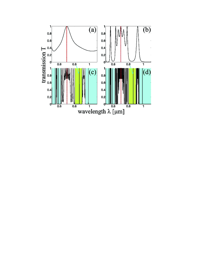
Figs. 1(a,b,c,d) show the linear transmission spectra for plane waves (as calculated with the transfer matrix method, TMM, see Ref. [2]) for the T-M photonic crystals respectively, in the wavelength range - m. Normal incidence is assumed, i.e. vanishing incidence angle , so that TE- and TM-polarization spectra are degenerate. At this stage, forward and backward spectra also coincide (, ), since the linear transfer matrix is unimodular [2], and, despite the strong asymmetry of the considered lattices, no optical diode action is possible in the linear regime. Crystal parameters are: refractive indices of the layers (which corresponds to the polydiacetylene -BCMU organic material, see Refs. [10, 3]), (which corresponds to TiO2 material), , layer thicknesses nm and nm, where m (indicated with a dashed red line in Fig. 1). Total physical lengths of the crystals are approximately m for [ layers], m for [ layers], m for [ layers] and m for [ layers].
Several things can be deduced from the panel of Fig. 1. First of all, it is easy to see that, when increasing the generation number , each peak of transmission shows evidence of self-similarity. This is a very well-known feature which is discussed in many works [11]. Secondly, most of the peaks shown in Fig. 1 are peaks of perfect transmission (PPTs, for which ), regardless of the value of , and they tend to accumulate around the reference frequency , at which the quarter wavelength condition is satisfied. We have found that, amongst the basic quasiperiodic crystals, this unexpected property seems to be a unique and remarkable feature of T-M sequences. Another important feature shown in Fig. 1 is the gradual (for ) formation of pseudobandgaps, i.e. frequency regions of zero transmission (not due to periodicity) where the crystal behaves like a perfect mirror. In Figs. 1(c) and 1(d) one particular pseudobandgap under scrutiny is indicated with a green shaded region, while other pseudobandgaps (the ones containing other PRs) present in the spectra are indicated with blue areas. This gap contains a sharp resonance [pseudoresonance, PR, indicated with blue arrows in Fig. 1(c) and 1(d)], analogous to a defect state, that in presence of nonlinearity can be used to obtain nonreciprocal propagation. This is located at m. The generation of the above sharp resonances can be attributed to the specific localization phenomena in T-M sequences [12]. Both extended and critical states exist in T-M sequences, which give rise to two distinct types of bandgaps. One is the traditional bandgap that exists in periodic crystals, the other one shows fractal (self-similar) splitting into smaller bands. The above types of gaps are distinguished by their different behavior when increasing the generation number [12]. Traditional gaps change their depths only, while fractal gaps split, creating the sharp peaks of perfect transmission which are impossible to obtain with periodic crystals or resonators.
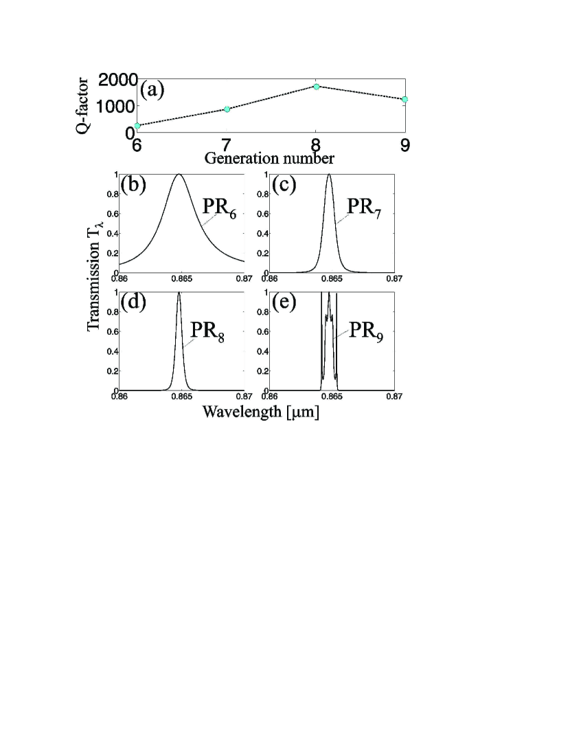
Quality factor (Q-factor) is a measure of the average energy in the resonant peak over the energy radiated per cycle [13]. It is defined by , where is the central resonant wavelength and is the resonance full-width at half maximum (FWHM). In Fig. 2(a) the evolution of Q-factor for the PR indicated above is shown as a function of generation number. The Q-factors for the PRj resonance are: , , and . The resonance appears (together with the pseudobandgap) at [Fig. 2(b)], and it has a well-defined bell-shape until [Fig. 2(e)], at which the fractal self-replication of the spectrum occurs. At this point the PR broadens due to the birth of satellite peaks. Remarkably, the central wavelength of the PR (where it exists) does not depend on . For the chosen index contrast, it thus makes sense to talk about this PR only for . However, we need to restrict ourselves to odd-order T-M sequences, the only ones that do not exhibit spatial symmetry. For this reason we select as our representative structure, which has the best PR specifics for the selected value of . In order for the pulse to clearly distinguish the resonance, its duration must be , where is the resonance FWHM. In the case of PR7 we have THz, so that a quasi-CW pulse is defined by psec. This, together with material relaxation time, will limit the device switching time.
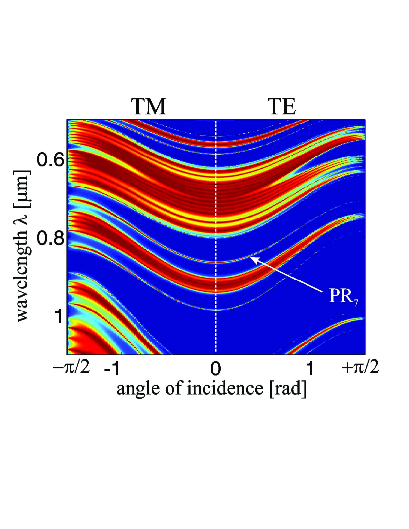
Before embarking in the nonlinear analysis of the structures, it is useful to understand how small random fluctuations in the angle of incidence of light from perfect normal incidence () affect the transmission spectra for TE- and TM-polarizations. Fig. 3 shows the -dependence of TE- and TM-polarization spectra for . Position of the PR7 peak is also indicated. For (normal incidence), the two output spectra must coincide. The most important feature that can be deduced from Fig. 3 is the presence of minima in the peak positions in correspondence of the ’degeneracy’ point , a desirable feature for what concerns device applications. This leads to a solid structural stability of the PR to small random fluctuations in , which will therefore be polarization-independent to a high degree of approximation.
3 Nonlinear transmission and optical diode action
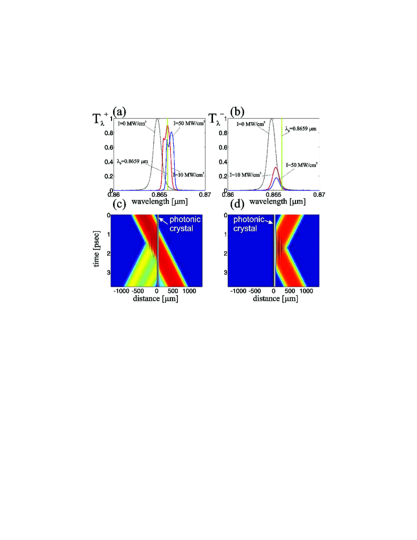
We now proceed to analyze the nonlinear behavior of the PR7 peak shown in Fig. 2(c). In order to do this, we use the nonlinear TMM method outlined in Ref. [3]. According to this method, for each value of the input wavelength , we must guess the output forward amplitude, while the backward output amplitude vanishes. After propagating back to the input layer, one obtains a value for the total input intensity, which is proportional to the sum squared of the input forward and backward fields. We repeat this process until the input intensity matches the desired incident intensity. Figs. 4(a,b) display a sketch of the different nonlinear frequency shifts of PR7 for three different input intensity conditions (, black dotted lines; MW/cm2, solid red lines; and MW/cm2, solid blue lines), for both forward [Fig. 4(a), ] and backward [Fig. 4(b), ] incidence. The nonlinear Kerr refractive indices for TiO2 and -BCMU used in our calculations are roughly estimated to be cm2/W and cm2/W. These are measured values [14, 10], obtained by using degenerate and non-degenerate pump-probe experiments. Results published in [10] show that linear and nonlinear absorptions can be minimized considerably in -BCMU inside certain spectral regions, which are therefore suitable for device operation. Thus here we neglect these two absorptions for simplicity. The relaxation time of -BCMU is estimated to be around psec. The switching time of the device is fast and equal to .
Let us take, for instance, an input pump intensity equal to MW/cm2, corresponding to the curves displayed with red solid lines in Figs. 4(a,b). Note the strong difference in transmission between forward and backward incidence. Moreover, there is a reduction of the transmission peaks with increasing intensity. By tuning the pump wavelength near the maximum of the forward incidence peak [ m, see green vertical dashed line in Fig. 4(a)], one has substantial transmission for forward incidence of pump light (). However, for the same wavelength, the backward transmission is located on the tail [see green vertical dashed line in Fig. 4(b)], which ensures a very low transmission for the backward direction (). For the particular case shown in Figs. 4(a,b), this gives an efficient diode action with an AOD contrast equal to . The resonant nature of the PR enhances the nonlinear effects to a point that the AOD action is obtained by using modest intensities.
4 Pulse propagation
Finally, in order to confirm the results obtained above for realistic quasi-CW pulses, which have a small but finite spectral width well inside the resonance, we accurately solve Maxwell’s equations in presence of an inhomogeneous permittivity . Let us write the 1D Maxwell equations in the conventional form , , where and are the scalar electric and magnetic fields respectively, is the speed of light in vacuum. is the dielectric permittivity, where is the refractive index (real and ), and is the Kerr-nonlinear dielectric constant. is the electric field intensity. We then decouple the fast spatiotemporal oscillations due to the carrier wavenumber and frequency with the expansion: , . and are the complex envelopes of the electric and magnetic fields respectively, and . After defining new dimensionless variables and , where and are respectively arbitrary spatial and temporal scales, we choose and . We also rescale the fields as , where is a convenient reference intensity. This leads to the dimensionless equations
| (1) | |||
| (2) |
which are suitable for numerical computations, and do not rely on any slow-varying amplitude approximation. An important observation is that the nonlinear dielectric function is given in the new variables by , a non-trivial expression that satisfies simultaneously the terms rotating with the first and the third harmonics. Eqs.(1-2) are solved by first initializing as a function of , at , and then posing , where the plus (minus) sign refers to a forward (backward) propagation condition, which is used to test the forward/backward asymmetry in our T-M structure.
Results of simulations are shown in Fig. 4(c,d). Fig. 4(c) shows the nonlinear transmission of a forward supergaussian pulse with a temporal width of psec and a spatial width m ( than the structure’s length, which is m), and input wavelength m, corresponding to the location of the green dashed line in Figs. 4(a,b). The chosen supergaussian profile well approximates the incidence of a finite CW wave, and input intensity was taken to be MW/cm2. According to the previous discussions, this allows almost unitary transmission () if the spectral width of the pulse is narrower than that of the PR. Launching the same pulse in the backward direction we have a dramatically different behavior: Fig. 4(d) shows the nonlinear transmission in this case, where light is almost entirely reflected (), confirming both qualitatively and quantitatively the optical diode action and the plane-wave predictions discussed above.
5 Conclusions
In conclusion, we have studied the linear and nonlinear transmission properties of a micron-size T-M quasiperiodic PC near a PR, i.e. a sharp resonance located in the pseudobandgap. Sharp resonances are due to the unique field localization properties of T-M sequences. We have shown that the strong asymmetry of odd-order Thue-Morse lattices, combined with a Kerr nonlinearity, gives rise to a highly nonreciprocal transmission which is the major feature of an AOD. This effect has also been confirmed by numerically integrating Maxwell’s equations for realistic optical pulses. Our design allows an unprecedented reduction in size of the device at relatively low operational optical intensities, a consequence of the intrinsic antisymmetry of the structures considered, and the resonant, strongly localized nature of the transmission.
The author would like to thank Victor Grigoriev for useful comments. This work is supported by the UK Engineering and Physical Sciences Research Council (EPSRC).
References
- [1] E. Yablonovitch, Phys. Rev. Lett. 58, 2059 (1987); S. John, Phys. Rev. Lett. 58, 2486 (1987).
- [2] P. Yeh, Optical Waves in Layered Media (Wiley, New Jersey, 2005).
- [3] M. Scalora et al., J. Appl. Phys. 76, 2023 (1994); Tocci et al., Appl. Phys. Lett. 66, 2324 (1995).
- [4] K. Gallo and G. Assanto, Opt. Lett. 16, 267 (1999); K. Gallo et al., Appl. Phys. Lett. 79, 314 (2001).
- [5] L. J. Aplet and J. W. Carlson, Appl. Opt. 3, 544 (1964).
- [6] E. L. Albuquerque and M. G. Cottam, Polaritons in Periodic and Quasiperiodic Structures (Elsevier, Amsterdam, 2004).
- [7] D. Shechtman et al., Phys. Rev. Lett. 53, 1951 (1984).
- [8] R. Merlin et al., Phys. Rev. Lett. 55, 1768 (1985); Z. Cheng, R.Savit and R. Merlin, Phys. Rev. B 37, 4375 (1988).
- [9] A. Thue, Norske Vididensk. Selsk. Skr. I. 7, 1 (1906).
- [10] S. Molyneux et al., Opt. Lett. 18, 2093 (1993); A. K. Kar, Polym. Adv. Technol. 11, 553 (2000).
- [11] Nian-hua Liu, Phys. Rev. B 55, 3543 (1997).
- [12] W. Gellermann et al., Phys. Rev. Lett. 72, 633 (1994); H. Hiramoto and M. Kohmoto, Phys. Rev. Lett. 62, 2714 (1989); V. Agarwal et al., Photon. Nanostruct. 3, 155 (2005); X. Y. Jiang et al., Appl. Phys. Lett. 86, 201110 (2005); J. M. Luck et al., J. Phys. A: Math. Gen. 26, 1951 (1993).
- [13] D. Ripin et al., IEEE J. Light. Tech. 17, 2152 (1999).
- [14] R. Adair, L. L. Chase and S. A. Payne, Phys. Rev. B 39, 3337 (1989).
Fig. 1 Linear transmission spectra for plane waves at normal incidence () for asymmetric odd-order T-M photonic crystals (a) , (b) , (c) , (d) . Reference wavelength m is indicated with a red dashed line. The pseudobandgap and the PR of interest for this paper are indicated with a green area and a blue arrow respectively. Other large pseudobandgaps which contain other PRs are indicated with blue areas. Crystal parameters are: , , nm and nm.
Fig. 2 (a) Q-factors of PR at m as a function of generation number for T-M PCs. (b,c,d,e) Transmission spectra of the m PR for respectively. Crystal parameters are the same as in Fig. 1.
Fig. 3 -dependence of TM- and TE-polarization spectra (left and right parts of the plot respectively) for the linear T-M quasicrystal . Large blue regions correspond to pseudobandgaps. Crystal parameters are the same as in Fig. 1.
Fig. 4 (a,b) Sketch of nonlinear shifts for forward [(a)] and backward [(b)] incidence, for three different input intensities. (c,d) Results of pulsed simulations, showing the asymmetric transmission properties of the nonlinear device for forward [(c)] and backward [(d)] incidence. In both cases, input intensity is MW/cm2. The input pulse has a supergaussian profile, , with and m, which corresponds to a pulse duration of psec. The position of the T-M crystal is indicated by a vertical bar. Crystal parameters are the same as in Fig. 1.